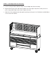
DX Series 72” Hutch shown assembled on DX722117RC 72” 17 Drawer Roller Cabinet with Promotional Bonus Power Tool Rack Accessory Model: DX722101HC Extreme Tools, Inc. 740 Frontenac Road Naperville, Illinois 60563 630.369.9303 www.ExtremeTools.net Sales@extremetools.net CustomerService@extremetools.
DX722101HC 72” Hutch Parts Diagram 3 2 5 8 1 9 4 10 15 16 11 6 7 12 14 13
DX722101HC PARTS LIST ITEM NO. 1 2 3 4 5 6 7 8 9 10 11 PART NUMBER QTY 7221-HC-01 7225HC-10 7221HC-13 GAS STRUT (300) 7221HC-02 Z-M5-08-35SHS Z--2MSP Z-M10 PLUG Z-M8-1.25X20FLCS 7221HC-08 Z-M5-08-35SHS Z--2MSP Z-M10 PLUG Z-M8-1.
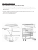
STEP 1 - Remove End Caps a. IMPORTANT! Engage the brakes on the casters of the roller cabinet! b. Remove plastic end caps from the top of the trim on the roller cabinet. c. Set aside to re-install later. A STEP 2 - Remove Trim from Side Panels a. Detach the covers from the vertical trim of the hutch side panel assemblies. b. Set aside to re-attach after hutch is assembled.
STEP 3 - Install Left Side Panel Assembly a. Insert the “J” end of the J-Connector into the rectangular opening at the top of the trim of the roller cabinet where the end cap was removed. The “J” end of the connector should be facing the body of the tool box. The top end with the threaded insert should be oriented to the front of the trim. b. Insert M8 Hex Bolt through top of the “L” Bracket and screw into the top of the threaded insert of the J-Connector. c.
STEP 4 - Install Back Panel a. Pull the laminated top/stainless steel top forward about 1/8” from the rear fence rail. b. With the assistance of another adult, set the bottom edge of the Back Panel between the rear fence rail and the back edge of the laminated top/stainless steel top. c. Align the Back Panel’s holes with the threaded inserts of the side panel assembly. Secure in place using (5) M6 Phillips head screws. Tighten all screws.
STEP 5 - Install Right Side Panel Assembly a. Use the same procedure outlined in Step 3 to install Right Side Panel Assembly. b. Align the Back Panel’s holes with the threaded inserts of the right side panel assembly. Secure in place using (5) M6 Phillips head screws. Tighten all screws. c. Attach the side mounting bracket through the opening on side panel. Use Flat Washer and M8 Bolt to secure to the roller cabinet.
Step 6 - Install Mounting Screws and Adjustable Shelf a. Locate the threaded inserts on each side panel. Choose the height for the shelf and install (2) M6 Screws halfway into the threaded inserts on right/left side panels. b. Locate the cutouts on sides of shelf. Install shelf by setting cutouts on top of installed M6 Screws on Side Panels. Threaded Inserts for installing screws for shelf.
STEP 7 - Install the Lid Install the Lid onto the body of the Hutch. LID IS HEAVY! LID INSTALLATION REQUIRES ASSISTANCE FROM AN ADULT to LIFT and MAY REQUIRE the USE of MECHANICAL EQUIPMENT to PROPERLY POSITION! a. Lift the lid into position on top of the hutch body as shown below. b. Insert the M5x35mm Screw into the round opening on the Side Panel. Push the screw into the threaded insert. Then, use the Allen Wrench (supplied with the parts) to drive the Screw all the way into the lid. c.
Step 8 - Install Gas Struts Inside Lid THIS STEP REQUIRES THE ASSISTANCE OF ANOTHER ADULT. a. With at least one other person holding the lid assembly open, install gas struts. Hold each gas strut so that the larger cylinder end is up and the smaller piston end is down. Insert the male portion at the larger cylinder end of the gas strut into the opening near the top lid stiffener. Tighten with 12mm open-end wrench to secure in place.
Step 9 - Final Assembly a. Re-attach the Vertical Trim Covers to the front of the Hutch Side Panels. b. Insert the End Caps into the openings at the top of the Vertical Trim Covers. c. Use the supplied hardware to attach the Power Strip on either the right or left side of the face of the adjustable shelf.
BONUS POWER TOOL RACK ACCESSORY INSTALLATION Step 10: Install Power Tool Rack a. The Power Tool Rack requires an adapter to hang on the edge of the shelf. (Adapter does not need to be used if hanging the Power Tool Rack on the top rail of a tool cart or roller cabinet.) Diagram 1 Slots on edge of shelf b. Attach the adapter to the shelf by inserting the top hooked portion of the adapter into the slots on the edge of the shelf as shown in Diagrams 1 & 2. c.
DX Series DX722101HC 72” Extreme Power Workstation® Hutch shown assembled on DX722117RC 72” 17 Drawer Roller Cabinet with Promotional Bonus Power Tool Rack Accessory