
- Extron Electronics Configurable Fiber Optic Digital Matrix Switcher Setup Guide


Refer also to the FOX 4G Matrix 14400 User’s Manual at www.extron.com.
Refer also to the FOX 4G Matrix 14400 User’s Manual at www.extron.com.
Making connections
a
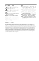
Fiber optic connectors and LEDs —
W
This unit outputs continuous invisible light, which
may be harmful and dangerous to the eyes; use with
caution. For additional safety, plug the attached dust
caps into the optical transceivers when the fiber optic
cable is unplugged.
N
Ensure that you use the proper fiber cable for your I/O
board. Typically, singlemode fiber has a yellow jacket and
multimode cable has an orange jacket.
N
The FOX 4G Matrix 14400 uses one connector on the
block as an input and the second connector on the same
block as a separate output.
Ä
Input connector —
Connect a fiber optic
cable between each Input
LC connector and a
FOX 500 Tx or any other
compatible Extron FOX
device.
N
Or, for the serial return (receiver-
to-transmitter) function, connect
the far end to the Optical 2
connector on a FOX Rx receiver.
Input LED — When lit, the link is
active (light is received).
Å
Output connector —
Connect a fiber optic cable
between each output
LC connector and a
FOX 500 Rx or any other
compatible Extron FOX device.
N
Or, for the serial return
(receiver-to-transmitter)
function, connect the far end
to the Optical 2 connector on a
FOX Tx transmitter.
Output LED — This LED is
always lit.
OUT
IN
OPTICAL
2* 1
*
OPTIONAL FOR
RETURN DATA
LINK
LINK
OPTICAL
Transmitting
Unit
Receiving
Unit
FOX 4G
Matrix 14400
Switcher
12*
*
OPTIONAL FOR
RETURN DATA
LINK
LINK
1b 1a
b
Remote port — If desired, connect a control system or computer
to the rear panel Remote RS-232/RS-422 port.
RS-232 Function Pin Function
1
2
3
4
5
6
7
8
9
—
TX
RX
—
Gnd
—
—
—
—
Not used
Transmit
Receive
Not used
Ground
Not used
Not used
Not used
Not used
—
TX–
RX–
—
Gnd
—
RX+
TX+
—
Not used
Transmit (–)
Receive (–)
Not used
Ground
Not used
Receive (+)
Transmit (+)
Not used
RS-422
5
1
96
Figure 2-6 — Audio output connector wiring
c
Ethernet port — If desired, connect a network WAN or LAN
hub, a control system, or a computer to the Ethernet RJ-45 port.
Network connection — Wire as a patch (straight) cable.
Computer or control system connection — Wire the interface
cable as a crossover cable.
N
The factory default IP address is 192.168.254.254.
d
Power connector — Plug the switcher into two grounded AC
sources.
N
For reliability, connect the Redundant power cord to either
an uninterruptible power source or to a power source that
is completely independent from the primary power source.
e
Primary and Redundant power supply indicator LEDs —
Green — Indicates that the associated power supply is
operating within normal tolerances.
Red — Indicates that the associated power supply is operating
outside the normal tolerances or has failed. See chapter 4,
“Maintenance and Modifications“ to replace the power supply.
FOX 4G Matrix 14400 • Installation
Installation, cont’d
2-4
FOX 4G Matrix 14400 • Installation
2-5