User Guide Audio Products XTRA™ Full Rack Series: XPA 2002 XPA 2002-70V XPA 2002-100V XPA 2003C-70V XPA 2003C-100V XPA 2004 Full-Rack 2-, 3-, and 4-Channel Mono and Stereo Audio Power Amplifiers 68-783-01 Rev.
Safety Instructions • English Warning This symbol is intended to alert the user of important operating and maintenance (servicing) instructions in the literature provided with the equipment. Power sources • This equipment should be operated only from the power source indicated on the product. This equipment is intended to be used with a main power system with a grounded (neutral) conductor. The third (grounding) pin is a safety feature, do not attempt to bypass or disable it.
FCC Class B Notice This equipment has been tested and found to comply with the limits for a Class B digital device, pursuant to part 15 of the FCC Rules. These limits are designed to provide reasonable protection against harmful interference in a residential installation. This equipment generates, uses and can radiate radio frequency energy and, if not installed and used in accordance with the instructions, may cause harmful interference to radio communications.
Conventions Used in this Guide In this user guide, the following are used: NOTE: A note draws attention to important information. TIP: A tip provides a suggestion to make working with the application easier. CAUTION: WARNING: A caution indicates a potential hazard to equipment or data. A warning warns of things or actions that might cause injury, death, or other severe consequences. Copyright © 2011 Extron Electronics. All rights reserved.
Contents Introduction............................................................ 1 About this Guide................................................. 1 Terms Used in this Guide.................................. 1 Features............................................................... 2 Installation.............................................................. 3 Application Examples........................................... 3 Operation.................................................................
Introduction About this Guide This guide contains information about the Extron® series of audio power amplifiers: the XPA 2002 two-channel stereo amplifier, the XPA 2002-70V two-channel, 70 V line distribution mono amplifier; the XPA 2002-100V two-channel, 100 V line distribution mono amplifier; the XPA 2003C-70V three-channel, stereo 4-ohm and 8-ohm, mono 70 V line distribution amplifier; the XPA 2003C-100V three-channel, stereo 4-ohm, 8-ohm, mono 100 V line distribution amplifier; and the XPA 2004 four-c
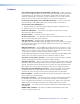
Features Extron Patented Class D Ripple Steering (CDRS™) technology — CDRS is an Extron patented technology that provides a smooth, clean audio waveform and an improvement in signal fidelity over conventional Class D amplifier designs. CDRS eliminates the high frequency switching ripple characteristic of Class D amplifiers, a source of RF emissions, which can interfere with sensitive A/V equipment such as wireless microphones.
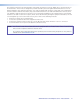
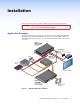
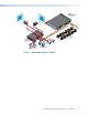
Installation This section discusses how to install the XTRA Series of full rack power amplifiers. WARNING: Installation and service must be performed by authorized personnel only (see “UL Rack Mounting Guidelines)”. Application Examples The following illustrations are application examples for the XPA 2002, XPA 2002-70V, XPA 2003C-70V, and XPA 2004. Application examples for the XPA 2002-100V and XPA 2003C-100V are very similar to the XPA 2002-70V and XPA 2003C-70V examples, respectively.
Extron XPA 2002-70V Power Amplifer V 02 -70 A 20 XP NG RI WI S 2 UTS AS CL OUTP 70V F 2 1 HP 2 CH 1 Hz 80 CH Hz 80 TS PU F IN Projector 2 Projector F OF OF 1 L VE LE STANDBY R/ ITE T LIM EC OT 2 PR 2 0 1 TE MO RE 0 1 L NA SIG 0 Hz 50/6 X V -240 MA 100 1.
T 2 PU -23 OUT RS A B L R L 6 O DI 3 T PU 4 5 R 8 IN 7 AU 2 1 T L Y R PU OUT ED LIST 3 1T2 . U S I.T.
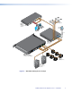
Extron SSP 7.1 Extron CrossPoint Ultra Series Surround Sound Processor Ultra-Wideband Matrix Switcher 1 P 7. SS 2 B SU ER OF WO S UT OU -23 RS Tx Rx CK R TP BA L E R SID L ER NT CE 8 7 OU 4 TP 6 S UT 5 T SE 3 RE 2 DI A 0.
Operation This section discusses how to operate the XPA power amplifiers.
a b Power indicator LED — This LED lights: zz Green when the amplifier is receiving full power. zz Amber when the amplifier is in Standby mode. Standby mode turns off all outputs from the amplifier, although the amplifier is still receiving power (see d of “Rear Panel Features and Operation).” Over Temp indicator LED — This LED lights red when the amplifier exceeds the recommended operating temperature for optimal lifetime. The LED turns off after the amplifier has cooled down sufficiently.
Rear Panel Features and Operation 5 100-240V LEVEL LISTED AUDIO/VIDEO APPARATUS 17TT GREEN - ACTIVE AMBER - STANDBY STANDBY REMOTE N15779 LIMITER/ PROTECT 1 2 1 14 1 3 2 6 14 12 10 8 BRIDGE MODE 2 1 2 4 2 2 0 0 OFF 7 6 BRIDGE ON (BRIDGE A) 6 4 26 4 1 2 12 10 8 18 SIGNAL XPA 2002 Rear Panel INPUTS XPA 2002 CLASS 2 WIRING OUTPUTS 1.5A, 50-60 Hz 8 /4 12 8 ( BRIDGE 8 ONLY ) 11 5 1.
5 100-240V LEVEL STANDBY REMOTE N15779 LISTED AUDIO/VIDEO APPARATUS 17TT GREEN - ACTIVE AMBER - STANDBY LIMITER/ PROTECT 1 2 3 4 1 2 3 2 12 10 8 4 6 6 14 3 12 10 8 4 26 SIGNAL XPA 2004 Rear Panel 1 14 18 6 14 6 14 12 10 8 6 4 2 0 1 4 12 10 8 4 2 0 INPUTS (BRIDGE A) 2 BRIDGE MODE 3 4 A (BRIDGE B) BRIDGE A B 1 ON BRIDGE B 2 3 4 4 2 0 XPA 2004 CLASS 2 WIRING OUTPUTS 1.
g Level adjustment (channels 1, 2, 3 and 4) — Use a Tweeker or small screwdriver to LEVEL adjust the audio input level for the corresponding channel. The analog potentiometers control the level from = (full attenuation) to 0 dB (no attenuation). 14 1 2 3 4 12 10 8 12 10 8 12 10 8 12 10 8 6 14 18 4 26 4 2 6 14 6 4 2 0 h 6 14 4 2 0 0 2 0 Balanced or unbalanced stereo/mono audio input connector — Wire the 3.5 mm 3-pin captive screw connectors for balanced or unbalanced input.
i High pass filter toggle switch — Use a small screwdriver to toggle this recessed two-position toggle switch that alternates between Off (no filtering) and 80 Hz. The XPA 2002-70V and XPA 2002-100V have 2 switches, one for each output channel. The XPA 2003C-70V and XPA 2003C-100V have one switch for the line distribution output channel (channel 3). Setting the switch to 80 Hz prevents the saturation of the speaker input transformers by low frequency signals.
Step 1: Strip and insert the speaker wires into the connector and tighten the captive screws. Be sure to observe correct polarity. Do not tin the wires! Step 2: Insert the wired connector into the amplifier output and secure the locking screws on either side. UT TP OU70V k Stereo audio output connector — Wire the included 4-pole, 5 mm screw lock captive screw connector to output 2-channel (XPA 2002, XPA 2003C-70V, and XPA 2003C-100V) or 4-channel (XPA 2004) audio.
Step 1: Strip and insert the speaker wires into the connector and tighten the captive screws. Be sure to observe the correct polarity. Do not tin the wires! Step 2: Insert the wired connector into the amplifier output and secure the locking screws on either side. UT TP 2 OU 1 l Bridged output mode (XPA 2002 and XPA 2004) — The output power of the XPA 2002 can be effectively doubled by using input channel 1 and bridging the outputs.
Bridged Mode Output XPA 2002 bridged mono output speaker wiring In bridged mode, the output mode toggle switches for Input 1 (A) or Input 3 (B) or both must be set to the bridged (up) position, as shown below. For Input 1: The channel 1 “+” output terminal becomes the bridged:”+” output terminal and the channel 2 “+” output terminal becomes the bridged “-” output terminal, as shown below.
XPA 2004 bridged mono output speaker wiring In bridged mode, the output mode toggle switches for Input 1 (A) or Input 3 (B) or both must be set to the bridged (up) position, as shown below. For Input 1: The channel 1 “+” output terminal becomes the bridged:”+” output terminal and the channel 2 “+” output terminal becomes the bridged “-” output terminal, as shown below.
On the input end, only Input 1 or Input 3 or both is used in bridged mode, as shown below.
Reference Information This section discusses the specifications, part numbers, and accessories for the XTRA Series of audio power amplifiers. Topics that are covered, include: zz Specifications zz Part Numbers zz Mounting Specifications Audio Voltage gain XPA 2002, XPA 2004 ��������������� 23x (27 dB) XPA 2003C-70V/100V (ch. 1 and 2) 23x (27 dB) XPA 2002-70V, XPA 2003C-70V (ch. 3 only) 57x (35 dB) XPA 2002-100V, XPA 2003C-100V (ch.
Audio output Number/signal type XPA 2002 �������������������������������� XPA 2002-70V ������������������������� XPA 2002-100V ����������������������� XPA 2003C-70V ����������������������� 2 channels, 4 or 8 ohms; or 1 bridged mono, 8 ohms 2 channels, 70 V 2 channels, 100 V 2 channels, 4 or 8 ohms 1 channel, 70 V XPA 2003C-100V ��������������������� 2 channels, 4 or 8 ohms 1 channel, 100 V XPA 2004 �������������������������������� 4 channels, 4 or 8 ohms; or 2 bridged mono, 8 ohms Connectors XPA 2002 �����
S/N ������������������������������������������������� Damping factor XPA 2002-70V ������������������������� XPA 2002-100V ����������������������� XPA 2003C-70V Channel 1 or 2 ������������������� Channel 3 �������������������������� XPA 2003C-100V Channel 1 or 2 ������������������� Channel 3 �������������������������� XPA 2002, XPA 2004 ��������������� High pass filter XPA 2002-70V, XPA 2003C-70V 100 dB, 20 Hz - 20 kHz, unweighted >100 @ 25 ohms >100 @ 50 ohms >100 @ 8 ohms >100 @ 25 ohms >100 @ 8 ohms >100
Power consumption at 230 VAC, 50 Hz Typical (1/8 power) XPA 2002 ��������������������������� 4 ohms (x2): 85.6 watts 8 ohms (x2): 54.4 watts XPA 2002-70V ������������������� 70 V (x2): 85.6 watts XPA 2002-100V ����������������� 100 V (x2): 90.4 watts XPA 2003C-70V ����������������� 4 ohms (x2) + 70 V: 122.4 watts 8 ohms (x2) + 70 V: 92.9 watts XPA 2003C-100V ��������������� 4 ohms (x2) + 100 V: 123.3 watts 8 ohms (x2) + 100 V: 95.3 watts XPA 2004 ��������������������������� 4 ohms (x4): 146.
XPA 2004 ��������������������������� 29.0 watts (99 BTU/hr) 1/8 power XPA 2002 ��������������������������� 4 ohms (x2): 35.6 watts (122 BTU/hr) 8 ohms (x2): 29.4 watts (100 BTU/hr) XPA 2002-70V ������������������� 70 V (x2): 35.6 watts (122 BTU/hr) XPA 2002-100V ����������������� 100 V (x2): 40.4 watts (138 BTU/hr) XPA 2003C-70V ����������������� 4 ohms (x2) + 70 V: 47.4 watts (162 BTU/hr) 8 ohms (x2) + 70 V: 42.9 watts (146 BTU/hr) XPA 2003C-100V ��������������� 4 ohms (x2) + 100 V: 48.
Part Numbers Included Parts These items are included with each power amplifier, as indicated below.
Optional Accessories Description Part Number SI 3CT LP Ceiling speakers 42-103-03 SI 3C LP Ceiling speakers 42-103-13 SI 3 Surface mount speakers (black, white) 42-105-02, -03 SI 26CT Ceiling speakers 42-070-03 SI 26 Surface mount speakers (black, white) 42-072-02, -03 SI 28 Surface mount speakers (black, white) 42-073-02, -03 SF 228T Ceiling speakers 42-168-03 FF 120T Ceiling speakers 42-120-13 FF 220T Ceiling speakers 42-141-03 SPK14/1000 Non-Plenum 1000' (300 m) spool 22-152-03 SPK1
Mounting The XPA power amplifiers can be set on a table; mounted on a rack shelf; mounted under a desk or other furniture; or mounted in the plenum space above a ceiling-mounted projector. Tabletop Use Four self-adhesive rubber feet are included with the audio amplifier. For tabletop use, attach one foot at each corner of the bottom side of the unit and place the unit in the desired location.
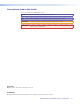
Mounting Screws 04 A 20 XP G IN IR 2W UTS SS CLAOUTP GE GE 3 4 DGE BRI Y ONL /8 ) (8 ) (8 ON 4 /8 F 3 2 1 L DGE BRI Y ONL 2 1 B A 4 4 A ID BR IDGE BRODE M TS PU IN B ID BR E B) OF IDG (BR E A) IDG VE LE (BR 4 3 0 2 0 1 E MOT STANDBY RE / ITER T LIM EC 4 OT 3 PR 2 1 0 0 AL SIGN 60 50/ X Hz 0V -24 A MA 100 1.3 ed List Mounting Ear uses 5 screws (ea side). Figure 5.
04 Ve Sp nt e ac F 3 OF E B) E MOT STANDBY RE GE 0 STANDBY /60 50 X V 40 MA 0-2 A 10 1.3 STANDBY / ITER T LIM EC 4 OT 3 PR 2 1 0 LE STANDBY / ITER T LIM EC 4 OT 3 PR 2 1 AL SIGN /60 50 X V 40 MA 0-2 A 10 1.3 Hz Ve ted Lis EO T 17TDIO/VIDS AUPARATU AP a Sp nt STANDBY / ITER T LIM EC 4 OT 3 PR 2 1 /60 50 X V 40 MA 0-2 A 10 1.3 STANDBY /60 50 X V 40 MA 0-21.3A STANDBY /60 50 X V 40 MA 0-21.3A STANDBY SIGN /60 50 X V 40 MA 0-21.
Extron® Warranty Extron Electronics warrants this product against defects in materials and workmanship for a period of three years from the date of purchase.