
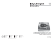
- Extron Electronics FSR Floor box-Mounted Interface Installation Guide

ii RGB 460
xixi
xixi
xi/472
xixi
xixi
xi/AAP 102 FSR Series • Table of Contents
Table of Contents, cont’d
RGB 460
xixi
xixi
xi/472
xixi
xixi
xi/AAP 102 FSR Series • Installation Guide
About this Guide
This guide contains instructions for mounting two different
Extron computer interfaces and an adapter plate into FSR
®
floor
boxes. The interfaces are standard RGB 460
xi
series and RGB
472
xi
series interfaces tailored to fit the FSR floor box.
The AAP 102 FSR adapter plate is a blank faceplate for the FSR
floor box, to which any standard Extron AAP (Architectural
Adapter Plate) can be mounted.
In this guide, the terms “FSR interface” and “Interface” are used
interchangeably.
For information about operating and wiring the interface, refer
to the RGB 400
xi
Series User Manual, Part #68-542-01, or the RGB
470
xi
Series User’s Manual, Part #68-661-01, depending on the
specific product you are using.
Installation Overview
CAUTION
Installation and service must be performed by
authorized personnel only. These products must be
used with UL approved electrical boxes.
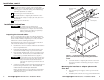
Install the interface or adapter plate as follows:
1
Turn all of the equipment off. Make sure that the
computer, the interface, and the output devices (projector/
monitor, speakers) are all turned off and disconnected
from the power source.
2
Select the installation location and install the electrical
floor box. Refer to the documentation that was included
with the floor box.
3
Route the cables that connect to the rear of the interface (or
the AAP(s) to be installed in the AAP 102 FSR adapter
plate).
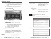
4
Set the gain and DIP switches (or the switch(es) on the rear of
the AAP(s) to be installed in the AAP 102 FSR adapter plate).
Refer to the RGB 400
xi
Series User Manual, Part #68-542-01, the
RGB 470
xi
Series User Manual, Part #68-661-01.
5
For the AAP 102 FSR adapter plate only, secure the
AAP(s) to the front of the faceplate.
6
Connect the video, audio, and power cables to the rear of the
device. Refer to the RGB 400
xi
Series User Manual, Part #68-
542-01, the RGB 470
xi
Series User Manual, Part #68-661-01.
7
Connect power cords and turn on the projector or monitor
and audio device, the interface, and the computer.
1