
User manual
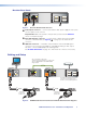
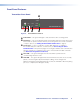


Receiver Rear Panel
1
2
3
4
POWER
12V
1.0A MAX
INPUT
OUTPUTS
AA
B
B
C
C
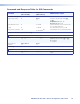
Figure 3. Receiver Rear Panel Connectors
A
Power input connector — Connect a provided 12VDC power supply into this 2-pole,
3.5 mm captive screw connector.
Important: Do not connect power to this port until you have read the Attention
notices on the previous page.
B
Input (twisted pair) connector — Connect the TP cable from the RJ-45 Output
connector of the transmitter (see figure 2,
C
, on page 3) to this female RJ-45
connector.
C
USB hub connectors — The built-in four port hub has four female USB Type A
connectors. The connections are USB 3.0 compatible, providing +5VDC at up to
500mA to connected USB peripherals requiring power.
See TP Cable Termination on page 15 to wire the RJ-45 connectors if necessary.
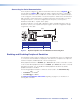
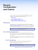
Cabling and Setup
USB
1
2
3
4
POWER
12V
1.0A MAX
INPUT
OUTPUTS
HOST
POWER
12V
1.0A MAX
INPUT
OUTPUT
Ground
+12 VDC
External
Power Supply
(12 VDC, 1 A )
G
–
External
Power Supply
(12 VDC, 1 A )
G
Ground
+12 VDC
–
Keyboard
Four USB 3.0 compatible type A female
connectors provide +5 VDC at up to
500 mA to connected USB peripherals.
Transmitter Receiver
UTP or STP CAT5 or higher cable:
Te rminate both ends identically, in accordance with
either the TIA/EIA T568A or the TIA/EIA T568B
wiring standard.
USB
Laptop
1A MAX
100-240V 50-60Hz
1A MAX
100-240V 50-60Hz
Figure 4. USB Extender Plus T-R Connection with Two External Power Supplies
USB Extender Plus T/R • Installation and Operation 5