CrossPoint Matrix Switchers CrossPoint 84, 88, 124, 128, 168, and 1616 HV and HVA 68-353-02 Rev.
Precautions Safety Instructions • English This symbol is intended to alert the user of important operating and maintenance (servicing) instructions in the literature provided with the equipment. This symbol is intended to alert the user of the presence of uninsulated dangerous voltage within the product's enclosure that may present a risk of electric shock. Warning Power sources • This equipment should be operated only from the power source indicated on the product.
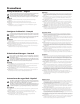
Quick Start — CrossPoint Matrix Switchers Installation 3 Step 1 Mount the switcher in a rack. 4 Tip Sleeve Step 2 Tip Sleeve Turn off power to the input and output devices, and remove the power cords from them. Unbalanced Input (high impedance) Tip Ring Sleeve (s) Tip Ring Step 3 Cable the switcher for RGBHV, RGBS, RGsB, RsGsBs, component video , S-video, or composite video input and output (3). See page 2-3 in this manual for details.
Quick Start — CrossPoint Matrix Switchers, cont’d Front Panel Controls Input and output buttons and LEDs select and identify inputs and outputs. Input buttons also select presets. On HVA models, the output LEDs also display the audio level of the selected input. Enter button saves changes when you change the configuration. Preset button saves a configuration as a preset or recalls a previously-defined preset. View button selects a view-only mode that prevents inadvertent configuration changes.
Table of Contents Chapter 1 • Introduction ....................................................................................................... 1-1 About the CrossPoint Series Matrix Switchers .................................................... 1-2 Features ................................................................................................................................... 1-3 Chapter 2 • Installation ........................................................................................
Table of Contents, cont’d Chapter 4 • Programmer’s Guide ..................................................................................... 4-1 Host-to-Switcher Instructions ....................................................................................... 4-2 Switcher-Initiated Messages ......................................................................................... 4-2 Switcher Error Responses ...............................................................................................
CrossPoint Matrix Switchers 1 Chapter One Introduction About the CrossPoint Series Matrix Switchers Features
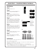
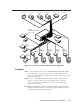
Introduction, cont’d Introduction About the CrossPoint Series Matrix Switchers The Extron CrossPoint Series Matrix Switchers are analog RGBHV matrix switchers that distribute any input to any combination of outputs. The matrix switchers can route multiple input/output configurations simultaneously.
Class Room 101 Class Room 103 Class Room 102 Class Room 104 Class Room 105 Class Room 106 Extron CrossPoint 128 HVA Matrix Switcher Extron DVS 204 REMOTE ,Y,B-Y RGB/R-Y UTS Scaler B OUTP G S R S V INPUT RGB SDI H RU/ PASS-TH RGBcS B-Y 8 7 6 /C 700 VSC RTER 5 VIDEO Y CONVE 3 1 SCAN 4 2 R-Y X MIN/MA 3 E SIZE N/SIZ ER/PA 2 CENT NEXT MENU 1 12 E 11 FREEZ RESET IR 10 9 8 Extron VSC 700 7 Scan Converter 6 5 4 3 2 1 DVD VCR Extron DVS 204 REMOTE ,Y,B-Y Scaler RGB
Introduction, cont’d Operational flexibility — Operations such as input/output selection, setting of presets, and adjustment of audio levels can be performed on the front panel or over the RS-232/RS-422 link. The RS-232/RS-422 link allows remote control via a control system. • QuickSwitch Front Panel Controller (QS-FPC™) — The CrossPoint series QS-FPC feature supports touch-of-a-button input and output selection, preset creation and selection, and audio gain and attenuation control.
Remote control — The CrossPoint switchers are remote controllable, using the MKP 1000 master control keypad and any combination of MCP 1000 slave control panels and/or MKP 1000 slave control keypads. The remote control devices are easy to use and provide tactile buttons for quick selection. Each MCP 1000 can be used for one-touch switching for a particular output and selecting global presets. Each MKP 1000 dedicated to an output can be used to select a different input for that output or to select a preset.
Introduction, cont’d 1-6 CrossPoint Matrix Switchers • Introduction
CrossPoint Matrix Switchers 2 Chapter Two Installation Rack Mounting the Switcher Cabling and Rear Panel Views
Installation, cont’d Installation Rack Mounting the Switcher The CrossPoint 84, 88, 124, and 128 Matrix Switchers are housed in rack-mountable, 3U high, 19” wide metal enclosures. The CrossPoint 168 and 1616 are in 6U high enclosures. The appropriate rack mount kit is included with each switcher. Rack mount the switcher as follows: 1. Insert the switcher into the rack, align the holes in the mounting bracket with those of the rack. 2. Secure the switcher to the rack using the supplied machine screws.
Video input and output connections All video input and output connections to the CrossPoint switchers are made with female BNC connectors. Some types of video output devices do not have BNC video output connectors. For these cases, a suitable cable or connector adapter is necessary between the device output connector and the BNC input connector of the CrossPoint. 2 RGBHV video inputs — Connect RGBHV video inputs to these BNC connectors for each input.
Installation, cont’d Tip (+) Ring (-) Tip (+) Sleeve ( ) Sleeve ( ) 3.5 mm Stereo Plug Connector RCA Connector (balanced) Figure 2-4 — Typical audio connectors The audio level for each input can be individually set, via the front panel or RS-232/422, to ensure that the level on the output does not vary from input to input. See chapter 3, Operation, chapter 4, Programmer’s Guide, and chapter 5, Matrix Software for details. 5 Connections for audio outputs — These 3.
1 2 3 4 5 6 7 8 1 2 3 4 5 6 7 8 7 8 INPUTS Figure 2-6 — Rear panel view, CrossPoint 84HV 1 2 3 4 5 6 7 8 5 6 7 8 1 2 3 4 5 6 INPUTS 1 2 3 4 1 2 3 4 Figure 2-7 — Rear panel view, CrossPoint 84HVA 1 2 3 4 5 6 7 8 1 2 3 4 5 6 7 8 7 8 INPUTS Figure 2-8 — Rear panel view, CrossPoint 88HV 1 2 3 4 5 6 7 8 5 6 7 8 1 2 3 4 5 6 INPUTS 1 2 3 4 1 2 3 4 5 6 7 8 Figure 2-9 — Rear panel view, CrossPoint 88HVA 1 2 3 4 5 6
Installation, cont’d 1 1 2 2 3 3 4 4 5 6 5 7 6 8 7 9 8 10 9 10 11 11 12 12 1 1 2 2 3 3 4 5 6 7 8 4 Figure 2-11 — Rear panel view, CrossPoint 124HVA 1 2 3 4 5 6 7 8 9 10 11 12 1 2 3 4 5 6 7 Figure 2-12 — Rear panel view, CrossPoint 128HV 1 3 5 7 9 11 13 15 1 3 5 7 9 11 13 15 2 4 6 8 10 12 14 16 2 4 6 8 10 12 14 16 1 3 5 7 9 11 13 15 1 3 5 7 9 11 13 15 2 4 6 8 10 12 14 16 2 4 6 8 10 12 14 16
1 3 5 7 9 11 13 15 1 3 5 7 9 11 13 15 2 4 6 8 10 12 14 16 2 4 6 8 10 12 14 16 1 3 5 7 9 11 13 15 1 3 5 7 9 11 13 15 2 4 6 8 10 12 14 16 2 4 6 8 10 12 14 16 1 3 5 7 9 11 13 15 1 3 5 7 9 11 13 15 2 4 6 8 10 12 14 16 2 4 6 8 10 12 14 16 1 3 5 7 9 11 13 15 1 3 5 7 9 11 13 15 2 4 6 8 10 12 14 16 2 4 6 8 10 12 14 16 1 3 5 7 9 11 13 15 1 3 5 7 9 11 13 15 2 4 6 8 10 12
Installation, cont’d 2-8 CrossPoint Matrix Switchers • Installation
CrossPoint Matrix Switchers 3 Chapter Three Operation Front Panel Controls and Indicators Front Panel Operations Rear Panel Controls Troubleshooting Worksheets
Operation, cont’d Operation Front Panel Controls and Indicators The front panel controls (figure 3-1 and figure 3-2) are grouped into two sets. The input and output buttons and LED indicators are grouped on the left side of the control panel. The control buttons and input/output (I/O) selection buttons and indicators are grouped on the right side of the panel. While the number of inputs and outputs varies depending on the size of the matrix, there are only two front panel arrangements.
Current configuration — The configuration that is currently being used (also called configuration 0). Global memory preset — A configuration that has been stored. Up to twelve global memory presets (CrossPoint 84, 88, 124, and 128) or sixteen global memory presets (CrossPoint 168 and 1616) can be stored in memory. The input buttons select the desired preset memory location to load or retrieve a preset. When a preset is retrieved from memory, it becomes the current configuration.
Operation, cont’d As a secondary function on HVA models, the Esc button increments the audio level of the selected input. In audio adjust mode, the Esc LED indicates a positive (+) gain value. A more detailed explanation of audio level adjustment is included in Viewing and adjusting the audio level (HVA models only) on page 3-13. I/O controls When creating or viewing a configuration, you must specify whether the configuration applies to video, audio, or both.
Front Panel Operations The following paragraphs detail the power-up process and then provide sample procedures for creating ties, sets of ties, and configurations; changing a configuration; viewing ties, sets of ties, and configurations; saving a preset; recalling a preset; and viewing and adjusting the audio level. Power On all models, power is automatically applied when the power cord is connected to an AC source.
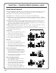
Operation, cont’d blinking selections, or toggled off by pressing the associated output button. Example 1: Create a set of video and audio ties See figure 3-4 and the following steps for an example in which input 5 is tied to outputs 3, 4, and 8. This example assumes that there are no ties in the current configuration.
output 3, output 4, and output 8; and audio input 5 tied to audio output 3, output 4, and output 8.
Operation, cont’d 5 1 2 3 4 LED key: INPUTS 6 7 5 8 9 10 11 = off, = on, AUDIO 12 CONTROL 1 2 3 4 5 OUTPUTS 6 7 8 Press 3 D 8 4 ENTER PRESET VIEW I/O ESC RGBHV AUDIO Press E ENTER Figure 3-7 — Example 3, step D: Removing an audio tie E Press and release the Enter button. The input and output LEDs turn off. The current configuration is now defined as video input 5 tied to video output 1, output 3, output 4, and output 8; and audio input 5 tied to audio output 3 and output 8.
LED key: = off, F 1 2 3 4 5 = on, INPUTS 6 7 C Press RGBHV B 8 9 10 11 12 2 3 4 5 OUTPUTS 6 7 8 5 6 I/O ENTER PRESET VIEW C 2 AUDIO VIEW CONTROL 1 Press Press = flashes once ESC Press RGBHV AUDIO F 7 A ESC Figure 3-8 — Example 4: Viewing the current configuration, no input selected Example 4 shows the process of viewing the current configuration after the steps in Examples 1, 2, and 3 have been performed. A Press and release the Esc button. The Esc LED flashes once.
Operation, cont’d that the selected output LED, the tied input LED (input 5), and the output LEDs light for all of the outputs that are tied to the input. Press and release the RGBHV button to toggle the Video LED off (figure 3-10). If audio is broken away, the Audio LED stops blinking and lights. E If audio ties are established for input 5, the output LEDs for all audio outputs tied to input 5 light. If no ties are established for input 5, all output LEDs turn off.
blink to indicate the mute or return to their previous state to indicate the unmute. 5. Press and release the View button to return to normal switcher operation. 1. You can mute video and audio, video-only, or audio-only outputs. Pressing and releasing the RGBHV and Audio buttons toggles each selection on and off. 2. When you enter view-only mode, the output LEDs turn on for all outputs without ties. 3. The video mute function mutes the R, G, and B planes only; the H and V planes are still active. 4.
Operation, cont’d Press F 1 2 3 4 5 INPUTS 6 7 8 9 10 11 12 VIEW CONTROL 1 2 3 Hold B 4 5 OUTPUTS Hold 6 7 8 ENTER PRESET VIEW I/O ESC RGBHV AUDIO D B D 3 Hold 4 LED key: = on, = blinking, B E Hold 3 3 = off, E 4 4 F Figure 3-12 — Example 5, step D: Muting and unmuting outputs Using presets The current configuration (configuration 0) can be saved as a preset in any one of 12 preset memory addresses (CrossPoint 84, 88, 124, and 128) or 16 preset memory addresses (Cr
A Press and release the Esc button. The Esc LED flashes once. B Press and hold the Preset button for approximately 2 seconds until the Preset LED begins to blink, then release the Preset button. C Press and release the input 1 button. The input 1 LED flashes once. The Preset LED turns off. Example 7: Recall a preset See figure 3-14 and the following steps for an example of recalling a preset to become the current configuration.
Operation, cont’d the CrossPoint 168 and 1616, but the steps for displaying the value are the same. For this reason, figure 3-16 and figure 3-18 show the indications displayed on the CrossPoint 168 and 1616 without duplicating all of the actions shown in figure 3-15 and figure 3-17.
LED key: 5 1 2 3 4 6 5 7 = off (value 0dB), = on (value 1dB) B 10 11 12 13 14 15 2 3 4 5 7 6 9 8 OUTPUTS 10 11 12 13 14 15 I/O 16 VIEW 1 C B = blinking, TROL INPUTS 9 8 B ESC RGBHV AUDIO 16 C +8dB Figure 3-16 — +8dB displayed, CrossPoint 168 and 1616 Press and release the View ( ) button once to decrease the audio level displayed in the output LEDs by 1dB.
Operation, cont’d If another input button is pressed and released, the level value for the current input is saved and level value for the newly selected input is displayed. E Press and release the Audio button. The Audio LED stops blinking and the View ( ) LED (if lit), the Esc ( ) LED (if lit), the selected input LED, and all output LEDs turn off. Both the RGBHV and Audio LEDs light.
General checks 1. Ensure that all devices are plugged in and powered on. The switcher is receiving power if one of the input LEDs is lit. 2. Ensure an active input is selected for output on the switcher. 3. Ensure that the proper signal format is supplied. 4. Check the cabling and make corrections as necessary. 5. Call the Extron S3 Sales & Technical Support Hotline if necessary.
Operation, cont’d Worksheet example 2: Drawing ties Figure 3-20 continues from worksheet example 1 by showing the video and audio ties that make up the configuration of preset 3, a solid ink line shows video ties, and a dashed pencil line shows the audio ties. In this example, the image of the presenter, from the main podium camera (input 1), is displayed in the main hall (output 1), to the overflow crowd in the conference room (output 4), and in the lobby (output 8).
Worksheet example 3: Test configuration The A/V system in our fictional organization needs to be fine tuned on a regular basis. Figure 3-21 shows a typical test configuration, with an Extron video test generator (input 12) generating a test pattern to all monitors (outputs 1, 2, 3, 4, and 8). Sound checks are run from the CD player (input 5) to all audio systems (outputs 1, 2, 4, 5, and 8).
Operation, cont’d 3-20 CrossPoint Matrix Switchers • Operation
CrossPoint Matrix Switchers • Operation 3-21 2 2 Title: 3 3 4 4 5 5 Video: 6 6 7 7 8 8 9 9 Audio: Output destinations Fill in the preset number and use colors, or dashes, etc. to make connecting lines. Indicate if the configuration is for Video, Audio, or both.
Operation, cont’d 3-22 CrossPoint Matrix Switchers • Operation
CrossPoint Matrix Switchers 4 Chapter Four Programmer’s Guide Host-to-Switcher Instructions Switcher-Initiated Messages Switcher Error Responses Using the Command/Response Table Command/Response Table
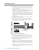
Programmer’s Guide, cont’d Programmer’s Guide The switcher’s rear panel RS-232/RS-422 connector (figure 4-1) can be connected to the serial port output of a host device such as a computer, RS-232 capable PDA, or control system. This connection makes software control of the switcher possible.
The switcher does not expect a response from the host, but, for example, the host program might request a new status. Switcher Error Responses When the switcher receives an SIS command and determines that it is valid, it performs the command and sends a response to the host device. If the switcher is unable to perform the command because the command is invalid or contains invalid parameters, the switcher returns an error response to the host.
Programmer’s Guide, cont’d Command/Response Table Symbol Definitions: = Carriage return/line feed = Carriage return (no line feed) • = Space X1 = Input number 01 – 08 (CrossPoint 84, 88); 01 – 12 (CrossPoint 124, 128); 01 – 16 (CrossPoint 168, 1616) X2 = Output number 01 – 04 (CrossPoint 84, 124); 01 – 08 (CrossPoint 88, 128, 168); 01 – 16 (CrossPoint 1616) X3 = Input number (for tie) 0 – maximum number of inputs (0=disconnected) X4 = Audio gain 0 – 9 (1dB/step) X5 = Audio attenuation 1 – 15
Command/response table for SIS commands (Cont’d) Command ASCII Command Response (host to switcher) Additional description (switcher to host) Global presets Save current configuration as preset Example: 9, Recall a preset Example: 5. X8 X8 , Spr X8 Spr09 Command character is a comma. Save current ties as preset 9. . Rpr X8 Rpr05 Command character is a period. Recall preset 5, which becomes the current configuration.
Programmer’s Guide, cont’d Command/response table for SIS commands (Cont’d) Command ASCII Command Response Additional description (host to switcher) (switcher to host) Esc zG Esc zXXX ZapG•• ZapA•• ZapZ ZapXXX View video output tie Example: V/v v7% X2 % Out X2 •In X3 •Vid Out07•In02•Vid View audio output tie Example: V/v V3$ X2 $ View gain for input Example: View all output mutes V/v v4G VM X1 G Example2 (CrossPoint 168): View preset configuration VM V/v Resets Reset global presets Reset
CrossPoint Matrix Switchers 5 Chapter Five Matrix Software Matrix Switcher+ Control Program Button-Label Generator
Matrix Software, cont’d Matrix Software Two software programs accompany the CrossPoint Series switchers: • The Extron Matrix Switchers Control Program (Extron part number 29-01501), which communicates with the switcher via the RS-232/RS-422 port, provides an easy way for you to set up ties and sets of ties. If your CrossPoint Series switcher was previously set up for RS-232, and your computer comm port uses RS-422, you must change the switcher cabling to match the computer interface.
Figure 5-1 — Extron Matrix Switcher+ Control Program window (blank) Figure 5-2 — Sample program window (complete) 4. To make the control program easier to use, assign a device icon to each input and output. Click on a box that represents an input or output, and drag the desired icon onto the box from the icon palette that appears. 5. To create a tie, drag an input box to one or more output boxes. To remove a tie, drag the output box to its tied input box.
Matrix Software, cont’d Go — Activates the selected preset as the current configuration. Save as — Allows the current set of ties to be saved as a preset. Enter the preset number when prompted to do so. Changes – Take — Allows you to save to file any changes made to the displayed configuration. Changes – Cancel — Returns to the previous screen, undoing any changes you have made.
Using emulation mode Emulation mode allows you to set up the software without attaching the switcher to the computer. To use emulation mode, do the following: 1. Start the program as described in step 1 on page 5-2. 2. Choose Emulate, and click OK. 3. Choose an emulation file to open, and click OK. The file DEMO.MTX provides a sample of a completed matrix setup. The file NEW.INI provides a blank setup to get you started. 4.
Matrix Software, cont’d Figure 5-3 — Extron’s Button-Label Generator window 5-6 CrossPoint Matrix Switchers • Matrix Software
CrossPoint Matrix Switchers A Appendix A Specifications Specifications Part Numbers
Specifications, cont’d Specifications Video Routing .......................................... 84 Series .................... 8 x 4 matrix 88 Series .................... 8 x 8 matrix 124 Series ................... 12 x 4 matrix 128 Series ................... 12 x 8 matrix 168 Series ................... 16 x 8 matrix 1616 Series ................. 16 x 16 matrix Gain ............................................... Unity Bandwidth .................................... 200 MHz (-3dB), fully loaded 0 - 10 MHz ...
Audio — audio models only Routing .......................................... 84 Series .................... 8 x 4 stereo matrix 88 Series .................... 8 x 8 stereo matrix 124 Series ................... 12 x 4 stereo matrix 128 Series ................... 12 x 8 stereo matrix 168 Series ................... 16 x 8 stereo matrix 1616 Series ................. 16 x 16 stereo matrix Gain ............................................... Unbalanced output: 0dB, balanced output: +6dB Frequency response .......
Specifications, cont’d 168/1616 Series ................... 10.5" H x 17.0" W x 9.7" D (6U high, full rack width) (26.7 cm H x 43.2 cm W x 24.6 cm D) (Depth excludes connectors. Width excludes rack ears.) Product weight 84/88/124/128 Series .......... 14.8 lbs (6.7 kg) 168/1616 Series ..................... 19.4 lbs (8.8 kg) Shipping weight 84/88/124/128 Series .......... 21 lbs (10 kg) 168/1616 Series ................... 26 lbs (12 kg) DIM weight 84/88/124/128 Series .......... 25 lbs 168/1616 Series .......
Cables When using signals with a scanning frequency of 15-125 kHz and running distances of 100 feet or more, use high resolution BNC cables to achieve maximum performance. Bulk cable Extron Part RG6 super high resolution cable Bulk RG6-1, 500’ Bulk RG6-1, 1000’ Bulk RG6-4, 500’ Bulk RG6-5, 500’ RG6 male crimp connectors, qty.
Specifications, cont’d Extron Part BNC-5 Mini HR Cable BNC-5-25’ MHR (25 feet/7.5 meters) BNC-5-50’ MHR (50 feet/15.0 meters) BNC-5-75’ MHR (75 feet/23.0 meters) BNC-5-100’ MHR (100 feet/30.0 meters) BNC-5-150’ MHR (150 feet/45.0 meters) BNC-5-200’ MHR (200 feet/60.0 meters) BNC-5-250’ MHR (250 feet/75.0 meters) BNC-5-300’ MHR (300 feet/90.
CrossPoint Matrix Switchers B Appendix B Reference Information Hardware Upgrades Button Labels
Reference Information, cont’d Reference Information Hardware Upgrades This appendix contains procedures for performing hardware maintenance procedures such as swapping the RS-232 and RS-422 ports, installing a new firmware update, and replacing the fuse. Opening the switcher Before you can perform any of the hardware upgrade procedures, you must open the switcher. The interior of the CrossPoint 84, 88, 124, and 188 switchers is accessed by removing the top cover.
Opening the CrossPoint 168 and 1616 To open the CrossPoint 168 or 1616 switcher, do the following: 1. Disconnect the power cord from the switcher. CAUTION Do not strain the three internal cables connected to the front panel. Too much strain can be damage the cables. CAUTION Do not touch the components inside the switcher without being electrically grounded. Electrostatic discharge (ESD) can damage ICs, even if you cannot feel, see, or hear it. 2.
Reference Information, cont’d Closing the switcher 1. Reinstall any cables removed. To plug a self latching cable into the desired receptacle, align the holes in the connector with the pins in the receptacle, and press evenly until the receptacle tabs lock into place. Ribbon cable Self-latching receptacle 2. Place the top cover (CrossPoint 84, 88, 124, and 128) and/or front cover (all models) in place and replace all the screws removed in Opening the switcher on page B-2.
8. If the switcher was removed from a rack, remove its power cord, reattach the switcher to the rack, and reconnect the power cord. 9. Reconnect the input and output cables. Installing a firmware update The IC that contains the firmware for the matrix switcher also contains the memory in which presets and audio levels are saved. When you replace the IC, these settings will be lost. You may want to record the presets and audio levels before you replace the IC.
Reference Information, cont’d If you choose to check for proper operation before putting the cover back on, ensure that tools and hands are outside the switcher and then perform step 11. After recognizing the new IC, the switcher should power up normally. Unplug the AC power cord, and reinstall the switcher. 11. Reinitialize the switcher to recognize the new IC as follows: a. Connect the power cord to the AC power source. b.
Figure B-5 — Button label blanks, 16-button strip CrossPoint Matrix Switchers • Reference Information B-7
Reference Information, cont’d B-8 CrossPoint Matrix Switchers • Reference Information
FCC Class A Notice Note: This equipment has been tested and found to comply with the limits for a Class A digital device, pursuant to part 15 of the FCC Rules. These limits are designed to provide reasonable protection against harmful interference when the equipment is operated in a commercial environment. This equipment generates, uses and can radiate radio frequency energy and, if not installed and used in accordance with the instruction manual, may cause harmful interference to radio communications.
www.extron.com Extron Electronics, USA Extron Electronics, Europe Extron Electronics, Asia Extron Electronics, Japan 1230 South Lewis Street Anaheim, CA 92805 USA 714.491.1500 Fax 714.491.1517 Beeldschermweg 6C 3821 AH Amersfoort The Netherlands +31.33.453.4040 Fax +31.33.453.4050 135 Joo Seng Road, #04-01 PM Industrial Building Singapore 368363 +65.6383.4400 Fax +65.6383.4664 Daisan DMJ Building 6F 3-9-1 Kudan Minami Chiyoda-ku, Tokyo 102-0074 Japan +81.3.3511.7655 Fax +81.3.3511.