
- Extron Electronics CVEQ1, CVEQ1 WM, CVEQ1 AAP User's Manual

CVEQ1, CVEQ1 WM, CVEQ1 AAP • Installation, Setup, Operation
CVEQ1, CVEQ1 WM, CVEQ1 AAP • Installation, Setup, Operation
Installation, Setup, Operation, cont’d
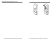
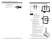
Mounting the CVEQ1 AAP
The CVEQ1 AAP and any other adapter plates must be attached
to a device’s faceplate or an AAP wallplate and cabled before
the device or wallplate is installed in a wall or furniture. The
screws needed for installing the CVEQ1 AAP are built into its
front panel, so no additional screws will be needed.
1. Insert the CVEQ1 AAP’s screws through the holes in the
faceplate or AAP wallplate. Secure the line driver to the
faceplate/wallplate with the provided captive washers
and #4-40 nuts.
#4-40 Nut w/ Captive
Washer
4-gang Wall Box
RGB 568
CVEQ1 AAP
RGB 568
INPUT
BU
FFERED
LOCAL MONITOR
POWER
AUTO
ID PIN 11
ID PIN 4
CS PIN 9
H. SHIFT
AUDIO
E
Q
UA
LIZ
E
GA
IN
AUD
IO
IN
PU
T
VID
EO INP
UT
L
R
CVEQ1 AAP
Mounting the CVEQ1 AAP to an interface
or wallplate and into a wall box
2. Follow steps
4
through
9
in the “Installation Overview”
section of this chapter.
2-11
changes the level and peaking of the output signal to
compensate for capacitance caused by up to 1000 feet (304.8
meters) of Extron SHR cable.
Use a small, flat-blade screwdriver to rotate this control. View
the display and select the setting that gives the sharpest picture.
For a more precise setting you can use an oscilloscope or a
waveform monitor connected to the far end of the output cable,
and adjust the equalization so that the color burst ranges
between -20 IRE and +20 IRE.
The Equalize control is a potentiometer with a soft
mechanical stop at the high and the low end. If you have
reached the high or low end of the adjustment, the
potentiometer makes a clicking sound as you turn it, and
no change is apparent on the display.
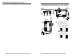
CVEQ1
AUDIO INPUT
VIDEO INPUT
LR
VIDEO OUTPUT POWERAUDIO OUTPUT
LR
Front
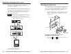
VCR
Stereo Audio
Stereo Audio
Large Screen
Projection TV
Rear
2-10
A typical CVEQ1 application