
- Extron Electronics Dual Link DVI Transmitter and Receiver User Manual

DVI DL 201 Tx/Rx • Installation
2-9
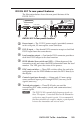
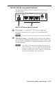
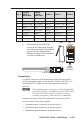
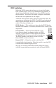
DVI DL 201 Tx rear panel features
The illustration below shows the rear panel features of the
DVI DL 201 Tx.
12V
0.4A MAX
POWER
DVI-D INPUT
LOCAL OUTPUT
OUTPUTS
DO NOT CONNECT
OUTPUTS TO LAN
1
2
3
SN XXXXXXXX E XXXXX 00/00
DVI DL TX
STORE
EDID
Tx Rx
CONTROL
PASS THRU
ON
1 2 3
ON
OFF
DEFAULT EDID
EDID MINDER
REMOTE DDC
2 3 4 5 6 7 8
DVI DL 201 Tx
DVI DL 201 Tx rear panel features
b
Power input — The 12 VDC power supply (provided) connects
to this two-pole, 3.5 mm captive screw connector.
c
DVI-D input — One female DVI-I connector accepts a dual-link
DVI-D input from the source device.
d
Local monitor output — One female DVI-I connector provides a
dual-link DVI-D output to the local monitor.
e
EDID Minder Store switch and LED — When depressed, the
transmitter reads and stores the EDID information from the local
monitor. The LED gives the status of this process.
f
DDC route switches — Three DIP switches allow the unit to be
congured to use the EDID Minder or route the DDC directly to
the display.
g
Control signal pass-through — A three-pole, 3.5 mm captive
screw connector inputs pass-through RS-232 (two-way) or IR
signals (one-way).
h
Twisted pair outputs — Three RJ-45 jacks are used for
transmitting DVI video, remote power, and communications/
control signals.
N
The DVI DL 201 transmits high frequency signals via
these TP outputs. Connections between the transmitter
and receiver must be point to point. It is recommended
that there should be no couplers, adapter, or patch panels
between the transmitter and receiver units.