
- Extron Electronics Dual Link DVI Transmitter and Receiver User Manual

DVI DL 201 Tx/Rx • Installation
Installation, cont’d
2-20
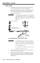
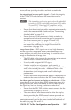
Power input
1. Connect the captive screw connector from the supplied
12 VDC power supply into the power receptacle.
Twisted pair cable 2, pin 5 carries a 12 VDC power signal.
This remote powering feature allows a single power
supply, connected to the transmitter, to power both the
transmitter and receiver.
C
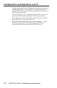
Power supply voltage polarity is critical. Incorrect
voltage polarity can damage the power supply, the
transmitter, and/or the receiver. Identify the ground
( ) lead by the ridges on the side of the cord (see the
figure below).
12V
0.4A MAX
POWER
Power Receptacle
DC Power Cord
Captive Screw Connector
AC Power Cord
Ground
+12 VDC
External
Power Supply
(12 VDC, 1 A )
Connecting power to DVI DL 201 Tx/Rx
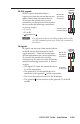
C
The ideal length of exposed wire in the stripping
process is 3/16" (5 mm). If longer than 3/16", the
exposed wires may touch, causing a short circuit.
If shorter than 3/16", the wires can be easily pulled
out even if tightly fastened.
Do not tin the wires. Tinned wire does not hold its
shape and comes loose over time.
2. Connect the AC power cord of the power supply unit to a
110 or 220 VAC electrical source.
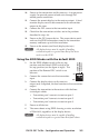
3. When the transmitter or receiver is getting power, either
directly from the power supply or indirectly through the
remote powering feature (receiver), the front panel LED
lights amber.
Power Supply
Output Cord
SECTION A–A
RidgesSmooth
A A