User’s Manual DVI DA2 and DVI DA4 Digital Visual Interface Distribution Amplifier 68-1376-01 Rev.
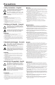
Precautions Safety Instructions • English This symbol is intended to alert the user of important operating and maintenance (servicing) instructions in the literature provided with the equipment. This symbol is intended to alert the user of the presence of uninsulated dangerous voltage within the product’s enclosure that may present a risk of electric shock. Caution Read Instructions • Read and understand all safety and operating instructions before using the equipment.
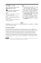
安全须知 • 中文 警告 这个符号提示用户该设备用户手册中 有重要的操作和维护说明。 电源 • 该 设 备 只 能 使 用 产 品 上 标 明 的 电 源 。 设 备 必须使用有地线的供电系统供电。 第三条线 (地线)是安全设施,不能不用或跳过。 这个符号警告用户该设备机壳内有暴 拔掉电源 • 为安全地从设备拔掉电源,请拔掉所有设备后 或桌面电源的电源线,或任何接到市电系统的电源线。 露的危险电压,有触电危险。 电源线保护 • 妥善布线, 避免被踩踏,或重物挤压。 注意 阅读说明书 • 用 户 使 用 该 设 备 前 必 须 阅 读 并 理 解所有安全和使用说明。 保存说明书 • 用户应保存安全说明书以备将来使 用。 遵守警告 • 用户应遵守产品和用户指南上的所有安 全和操作说明。 维护 • 所有维修必须由认证的维修人员进行。 设备内部 没有用户可以更换的零件。为避免出现触电危险不要自 己试图打开设备盖子维修该设备。 通风孔 • 有些设备机壳上有通风槽或孔,它们是用来防止 机内敏感元件过热。 不要用任何东西挡住通风孔。 锂电池 • 不正确的更换电池会有爆炸的危险。 必须使用 与厂家推荐的相同
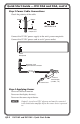
Quick Start Guide — DVI DA2 and DA4 To install, cable, and power on the DVI DA2 and DVI DA4: Step 1 Installation Install the DVI DA2 or DVI DA4 on a desk, mount it under a desk, or mount it in a rack. Step 2 DVI Cable Connections Connect a DVI cable from the Input connector to the video source device. Connect a DVI cable from the Local Output connector to the desired local output device. Connect a DVI cable(s) from the Output connector(s) to the desired display device(s).
Quick Start Guide — DVI DA2 and DA4, cont’d Step 3 Power Cable Connections Check the polarity of the cable. Smooth Ridges A A SECTION A–A Power Supply Output Cord Connect the 12 VDC power supply to the unit's power receptacle. Connect the 12 VDC power cord to an AC power outlet. POWER 12V 0.4A MAX Power Receptacle DC Power Cord Captive Screw Connector Ground +12 VDC AC Power Cord External Power Supply (12 VDC, 1 A ) Step 4 Applying Power Power on the local monitor.
Table of Contents Chapter One • Introduction ..................................................... 1-1 About This Manual .................................................................... 1-2 About the DVI DA2 and DVI DA4 .......................................... 1-2 DVI DA2 and DVI DA4 Features ............................................. 1-3 Chapter Two • Installation and Operation . .................. 2-1 Installation Overview . ..............................................................
Table of Contents, cont’d ii DVI DA2 and DVI DA4 • Table of Contents
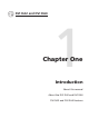
DVI DA2 and DVI DA4 1 Chapter One Introduction About this manual About the DVI DA2 and DVI DA4 DVI DA2 and DVI DA4 Features
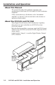
Installation and Operation About This Manual This manual describes the installation, operation, and specifications of the Extron DVI DA2 and DVI DA4 Distribution Amplifiers. Unless stated otherwise, all references to the "distribution amplifier" or "the unit" in this manual refer to the features or operation of both models. About the DVI DA2 and DVI DA4 These Digital Visual Interface (DVI) Distribution Amplifiers (DAs) have one input and either two (DVI DA2) or four (DVI DA4) outputs.
DVI DA2 and DVI DA4 Features External power supply — The DVI DA2 and DVI DA4 are powered by external 12 VDC power supply (provided with the units). DVI-D input — Both distribution amplifiers accept one single link DVI-D input, with a resolution range up to 1920 x 1200 or 1080p @ 60 Hz. Input Equalization — Input Equalization (EQ) conditions the input signals to ensure the integrity of the signals delivered to the output devices.
Introduction, cont’d 1-4 DVI DA2 and DVI DA4 • Introduction
DVI DA2 and DVI DA4 2 Chapter Two Installation and Operation Installation Overview Mounting the Distribution Amplifier Front Panel Features Rear Panel Features Cable Connections Operation Troubleshooting
Installation and Operation Installation Overview Both distribution amplifiers can be mounted on tabletops, under furniture, and in racks by following these steps: 1. Turn off all electrical equipment. Make sure that the input sources, the DA and the output display(s) are all turned off and all power sources and signal cables are disconnected. 2. Mount the unit as described in "Mounting the Distribution Amplifier", below. 3. Connect the Cables (see "Cable Connections" on page 2-8). 4.
5. Reliable earthing (grounding) — Maintain reliable grounding of rack-mounted equipment. Pay particular attention to supply connections other than direct connections to the branch circuit (such as the use of power strips). Rack mounting procedure These distribution amplifiers can be mounted on any of the following rack shelves: • RSF 123 (part # 60-190-20) 1U 3.5" VersaTools® rack shelf kit • RSB 123 (part # 60-604-21) 1U 3.
Installation and Operation, cont’d 4. Attach the shelf to the rack with the four provided 10-32 x 3.4" screws. Under-desk mounting The DVI DA2 and DVI DA4 can be mounted under furniture using the optional Extron MBU 125 under-desk mounting kit (part # 70-077-01). Under furniture mounting To mount the unit under a desk or table: 2-4 1. If necessary, remove rubber feet from the bottom of the unit. 2. Secure the under-desk mounting brackets to the unit with the four provided 4-40 x 3/16" screws. 3.
DVI DA2 and DVI DA4 • Installation and Operation 2-5
Installation and Operation, cont’d Front Panel Features DVI DA SERIES DVI DISTRIBUTION AMPLIFIER 1 Front panel features a 2-6 LED indicator — On both the DVI DA2 and DVI DA4, the LED indicator illuminates green when the unit is receiving power.
Rear Panel Features DVI DA2 SUPPORTS DVI-D ONLY POWER 12V 0.4A MAX INPUT 2 1 LOCAL OUTPUT OUTPUT 3 4 DVI DA4 POWER 12V 0.4A MAX DVI-D INPUT DVI-D OUTPUT 1 2 3 4 LOCAL OUTPUT 3 Rear panel features a b Power input — Connect the provided power supply to the 3.5 mm, 2-pole captive screw power receptacle. Input connector — Connect the input signal to the female DVI connector. The DVI input signal is equalized to ensure integrity.
Installation and Operation, cont’d Cable Connections DVI Connections 1. Use a DVI cable to connect the source device to the female DVI-I input. N Although DVI-I connectors are used, these distribution amplifiers are only compatible with single-link DVI-D video signals. For sources providing HDMI signals, use a HDMI to DVI adapter or cable, such as the Extron HDMIF-DVIDM female HDMI to male DVI-D adapter (#26-616-01) or the Extron HDMI M-DVI-D M series of HDMI male to DVI male cables (#26-614-xx).
DVI connector pin assignments The illustration below shows the pin assignments for the DVI-I male and female connectors. N Although DVI-I dual link connectors are used, the DVI DA2 and DVI DA4 are only compatible with single-link DVI-D video signals. DVI-I Dual Link - Female DVI-I Dual Link - Male (analog and digital) (analog and digital) 1 8 C1 C2 9 C5 C3 C4 Three rows of 8 holes and two contacts above and below the "+" socket.
Installation and Operation, cont’d Power Connections Connect the captive screw connector from the supplied 12 VDC power supply into the power receptacle. 1. Ensure the cable is connected with the correct polarity. N Smooth Ridges A A SECTION A–A Power Supply Output Cord Cable Polarity POWER 12V 0.4A MAX Power Receptacle DC Power Cord Captive Screw Connector Ground +12 VDC AC Power Cord External Power Supply (12 VDC, 1 A ) Connecting the power supply 2.
Operation 1. Connect the power supply (see page 2-10). 2. Connect and power on the local monitor (see page 2-8). 3. Connect and power on any other output displays (see page 2-8). 4. Connect and power on the source device (see page 2-8). N Output 1 (LOCAL OUTPUT) is used as a DDC reference and must be connected to the distribution amplifier before the source device.
Installation and Operation, cont’d Troubleshooting No output signal — Check that the front panel LED is on (lit green). If it is not, check the power supply connections to the unit (see page 2-10).
DVI DA2 and DVI DA4 A Appendix A Reference Information Specifications Included Parts Accessories
Reference Information Specifications N *Appropriate DVI-D to HDMI cables or adapters are required for HDMI signal input/output Video Maximum bit rate........................... Maximum pixel clock.................... Resolution range............................ Formats............................................ Standards......................................... 4.95 Gbps (1.65 Gbps per color) 165 MHz Up to 1920x1200 or 1080p @ 60 Hz RGB and YCbCr digital video DVI 1.0 Video Input Numbers/signal type...
Furniture mount................. Yes, with optional MBU 125 Under Desk Mounting Kit, #70-077-01 Enclosure type................................ Metal Enclosure dimensions.................... 1.75" H x 8.75" W x 3.0" D (1U high, half rack wide) (4.4 cm H x 22.2 cm W x 7.6 cm D) (Depth excludes connectors.) Product weight............................... 2.8 lbs (1.3 kg) Shipping weight............................. 5 lbs (3 kg) Vibration..........................................
Reference Information Included Parts These items are included: Included parts Replacement part number DVI DA2 60-886-01 DVI DA4 60-922-01 12 VDC Desktop power supply with orange captive screw attached 70-055-01 (1) IEC cord (4) Rubber feet (not attached) DVI DA2 and DVI DA4 User's Manual Accessories Accessories A-4 Part number DVID SL series (3, 6 or 15 feet single link DVI-D male to male patch cables) 26-585-0x IN9700 series (25, 35, 50 or 75 feet single link DVI-D male to male long distance
Extron’s Warranty Extron Electronics warrants this product against defects in materials and workmanship for a period of three years from the date of purchase.
Extron USA - West Headquarters +800.633.9876 Inside USA / Canada Only +1.714.491.1500 +1.714.491.1517 FAX Extron USA - East Extron Europe Extron Asia Extron Japan Extron China Extron Dubai +800.633.9876 +800.3987.6673 +800.7339.8766 +81.3.3511.7655 +81.3.3511.7656 FAX +400.883.1568 +971.4.2991800 +971.4.2991880 FAX +1.919.863.1794 +1.919.863.1797 FAX +31.33.453.4040 +31.33.453.4050 FAX +65.6383.4400 +65.6383.