DVS 150 Digital Video Scaler 68-459-01 Printed in the USA
Precautions Safety Instructions • English This symbol is intended to alert the user of important operating and maintenance (servicing) instructions in the literature provided with the equipment. This symbol is intended to alert the user of the presence of uninsulated dangerous voltage within the product's enclosure that may present a risk of electric shock. Warning Power sources • This equipment should be operated only from the power source indicated on the product.
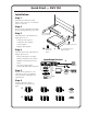
Quick Start — DVS 150 Installation Step 1 Install the four rubber feet on the bottom of the scaler (1A), or mount the scaler in a rack (1B). Step 2 Turn off power to the input and output devices, and unplug their power cords. Step 3 Attach the scaler to the input devices.
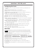
Quick Start — DVS 150, cont’d Configuring the Scaler Configuring the scaler: Press the input and rate buttons simultaneously, and hold them for two seconds. Stepping through the LCD display menus: Press the input button. Changing a selection: Turn the adjustment knob while the menu is displayed. Exiting the menus: Press the input button while the Detail menu is displayed, or don’t press any buttons or turn any knobs for eight seconds. AUTOSW — Choose whether the DVS automatically selects the active input.
Table of Contents Chapter 1 • Introduction ....................................................................................................... 1-1 About the Scaler .................................................................................................................. 1-2 Features ................................................................................................................................... 1-2 Chapter 2 • Installation ......................................................
Table of Contents, cont’d Appendix • Reference Information ............................................................................... A-1 Specifications ....................................................................................................................... A-2 Part Numbers ....................................................................................................................... A-3 DVS 150 part numbers ........................................................................
DVS 150 1 Chapter One Introduction About the Scaler Features
Introduction, cont’d Introduction About the Scaler Extron’s DVS 150 digital video scaler allows analog video signals (composite video, S-video, and component video) to be displayed on a device with a fixed resolution and aspect ratio, such as an LCD (liquid crystal display) projector, DLP (digital light processing) projector, or plasma display. The DVS 150 includes a 15-pin HD RGB pass-through connector for RGB input. Video signals coming into the scaler from this connector are not scaled.
• Power supply — Includes an internal, 100-240VAC, 50/60 Hz, auto-switchable power supply. • Precise image processing — Provides the latest in motion compensation, which produces motion images that are free of jaggies; a three-line adaptive comb filter, which eliminates chroma crawl; and a quad standard decoder, which ensures compatibility with NTSC (National Television Standards Committee) 3.58, NTSC 4.43, SECAM (sequential couleur avec mémoire), and PAL (phase alternate line) video standards.
Introduction, cont’d 1-4 DVS 150 Introduction
DVS 150 2 Chapter Two Installation Rear Panel Features Installation Front Panel Features Configuring the Scaler
Installation, cont’d Installation Rear Panel Features 8 100-240V 0.3A INPUTS VIDEO OUTPUTS B-Y REMOTE R G B H V S 1 R-Y Y S-VIDEO 2 50/60 Hz 1 2 3 RGB 3 4 RGB 4 5 6 7 Figure 1 — DVS 150 rear panel 1 AC power connector — Standard AC power connector attaches the scaler to any power source from 100VAC to 240VAC, operating at 50 Hz or 60 Hz. 2 Composite video input connector — One BNC female connector for composite video input.
6 Use the LCD menu screens to configure the scaler. See “Configuring the Scaler” on page 2-6. 7 The image from the input device should appear on the output device. If it does not, double check steps 3 and 4 and make adjustments as needed, and then see “Operating Problems” on page 5-2. Mounting the scaler Each DVS 150 ships with four uninstalled rubber feet. If you are going to rack mount the unit, do so before cabling it, and do not install the rubber feet.
Installation, cont’d Place the rubber foot on one corner of the scaler, and press it into place. 3. Position the rubber foot carefully before pressing it into place. It is difficult to move the foot after it is in place. 4. Repeat steps 2 and 3 to install a rubber foot on each of the remaining corners of the scaler. 5. Turn the scaler right side up and place it in the desired location.
You can install and run two output devices simultaneously, one using BNC connectors, and the other using the RGB connector. Front Panel Features INPUT 1 2 3 4 COLOR TINT BRIGHT CONT H SHIFT V SHIFT RATE DVS 150 DIGITAL VIDEO SCALER 1 2 3 4 5 6 7 8 9 10 11 Figure 6 — DVS 150 front panel 1 LCD — Displays configuration menus and status information. See “Configuring the Scaler” on page 2-6 and “Adjusting an image” on page 3-2.
Installation, cont’d Configuring the Scaler The LCD on the front panel of the scaler provides access to a menu that allows you to configure the scaler. • To access the menu, press the input button and the rate button simultaneously, and hold them for two seconds. The Autoswitch menu appears in the LCD. • To step through the menus, press the input button. • To exit the menu, step through the menus until the Detail menu appears, and then press the input button one more time.
VCR mode — Can eliminate horizontal noise if it is seen in a VCR image. To toggle between On and Off, turn the adjustment knob while the VCR mode menu is displayed. By default, VCR mode is set to Off. Blue mode — Turns off the red and green video output to allow you to set up color and tint using a color bar pattern. To toggle between On and Off, turn the adjustment knob while the Blue mode menu is displayed. By default, blue mode is set to Off.
Installation, cont’d 2-8 DVS 150 Installation
DVS 150 3 Chapter Three Operation Front Panel Operation
Operation, cont’d Operation Front Panel Operation The front panel includes an LCD screen that displays the current status of the scaler and the scan rate of the current video input signal. You can also use controls on the front panel to control the image display. A diagrams of the front panel is shown on page 2-5. Default screens By default, the LCD toggles between two screens every four seconds.
2. Turn the adjustment knob until the desired adjustment is accomplished. The LCD returns to the default screens, and the adjusted value is saved for future use by the active input, if you press the same button again or if you stop turning the knob for eight seconds. If an image control reaches its minimum, maximum, or default level, the LCD displays a screen similar to the screens shown in figure 9.
Operation, cont’d Freeze mode Freeze mode locks the output display to the current image. Freeze mode can be activated only by issuing an RS-232 command (see chapter 4 for IMAGE FROZEN more information). If freeze mode is activated, the LCD screen displays the message displayed at the left. If input 4 (RGB pass-through) is selected, you cannot activate freeze mode.
DVS 150 4 Chapter Four Serial Communication RS-232 Programmer’s Guide Remote Contact Closure Operation Control Software for Windows
Serial Communication, cont’d Serial Communication The scaler’s RS-232 connector can be connected to the serial port output of a host device such as a computer or control system. This connection makes software control of the scaler possible. Figure 10 shows a scaler RS-232 connection to a host serial port connector.
DVS error response When the scaler receives an SIS command and determines that it is valid, it performs the command and sends a response back to the host device. If the scaler is unable to perform the command because the command is invalid or contains invalid parameters, the scaler returns an error response to the host.
Serial Communication, cont’d Command/response table Symbol definitions: = CR/LF, • = space X1 = Inputs = 1 = Composite 2 = Component 3 = S-video 4 = RGB X2 = Adjustment range 1-127 X3 = Output rate = 1 = 640x480 @ 60 Hz 2 = 640x480 @ 75 Hz 3 = 800x600 @ 60 Hz 4 = 800x600 @ 75 Hz 5 = 832x624 @ 60 Hz 6 = 832x624 @ 75 Hz 7 = 852x480 @ 60 Hz 8 = 852x480 @ 75 Hz 9 = 1024x768 @ 60 Hz 10 = 1024x768 @ 75 Hz 11 = 1280x1024 @ 60 Hz 12 = 480p 13 = 720p 14 = 1080p 15 = 848x480 @ 60 Hz 16 = 1280x768 @ 56 Hz 17 = 1360x76
COMMAND Vertical shift Specific value Increment up Increment down ASCII X2 RESPONSE DESCRIPTION / Vph X2 Vph+ Vph– Selects vertical shift X2 Shift image up one step Shift image down one step = Rte Set the video output rate {/ }/ Set output rate X3 X3 Freeze Enable Disable F f Frz 1 Frz Ø Set freeze mode to On (freeze current displayed image) Set freeze mode to Off X x Exe 1 Exe Ø Set executive mode to On Set executive mode to Off Executive mode Enable Disable Query software version q Q
Serial Communication, cont’d Using the software 1. To run the Signal Enhancement Products Control Program, double-click on the Signal Enhancement Products Control Pgm icon in the Extron Electronics group or folder. The Comm menu appears on the screen. 2. Click on the comm port that is connected to the scaler’s RS-232 port. The Extron Signal Enhancement Products Control Program window appears. It displays the current settings and input type detected (see figure 11).
DVS 150 5 Chapter Five Troubleshooting Operating Problems
Troubleshooting, cont’d Troubleshooting This section gives recommendations on what to do if you have problems operating the DVS 150, and it provides examples and descriptions for some image problems you might encounter. Following are some tips to help you in troubleshooting. 1. Some symptoms may resemble others, so you may want to look through all of the examples before attacking the problem. 2. Be prepared to backtrack in case the action taken doesn’t solve the problem. 3.
Problem Cause Solution Picture controls are not active. Input 4 is selected. Switch to input 1–3. Input 4 is pass-through only (page 1-2). The image is green. The unit is configured for sync on green. Turn off sync on green (page 2-6). The image is too soft. The detail level Change the detail level (page 2-6). needs to be changed.
Troubleshooting, cont’d 5-4 DVS 150 Troubleshooting
DVS 150 A Appendix Reference Information Specifications Part Numbers
Reference Information, cont’d Reference Information Specifications Video input Number/signal type ................... 1 RGBHV, RGBS, RGsB pass-through 1 component video (Y, R-Y, B-Y) 1 S-video 1 composite video Connectors .................................... 3 BNC female ........................... component video 1 4-pin mini-DIN female ....... S-video 1 BNC female ........................... composite video 1 15-pin HD female ................ RGB pass-through Nominal level(s) ...........................
Rack mount ................................... Yes, with optional rack shelf, part #60-190-01 Enclosure type .............................. Metal Enclosure dimensions ................. 1.75" H x 8.75" W x 9.50" D 4.45 cm H x 22.22 cm W x 24.13 cm D Shipping weight .......................... 6 lbs (2.7 kg) Vibration ....................................... NSTA 1A in carton (National Safe Transit Association) Approvals ..................................... UL, CUL, CE, FCC Class B MTBF .......................
Reference Information, cont’d Assorted connectors BNC Connectors BNC Mini HR crimp connectors, qty. 50 BNC SHR crimp connectors, qty. 50 BNC Bulkhead connectors, qty. 50 (for custom wall plates) 100-074-51 100-075-51 100-076-51 Pre-cut cables BNC-4 HR cable is used for RGBS cable runs, and BNC-5 is used for RGBHV cable runs. Either type can also be used for RGsB (sync on green). All Extron BNC cables have male gender connectors at both ends. A plenum version of the BNC-5 HR cable is also available.
FCC Class B Notice This equipment has been tested and found to comply with the limits for a Class B digital device, pursuant to part 15 of the FCC Rules. These limits are designed to provide reasonable protection against harmful interference in a residential installation. This equipment generates, uses and can radiate radio frequency energy and, if not installed and used in accordance with the instructions, may cause harmful interference to radio communications.
EXTRON ELECTRONICS/RGB SYSTEMS, INC. 1230 South Lewis Street, Anaheim, CA 92805 800.633.9876 714.491.1500 FAX 714.491.1517 U.S.A. EXTRON ELECTRONICS, EUROPE Beeldschermweg 6C, 3821 AH Amersfoort +31.33.453.4040 FAX +31.33.453.4050 The Netherlands EXTRON ELECTRONICS, ASIA 135 Joo Seng Rd. #04-01, PM Industrial Bldg. +65.383.4400 FAX +65.383.4664 Singapore 368363 EXTRON ELECTRONICS INFORMATION EXTRONWEB™: www.extron.com EXTRONFAX™: 714.491.