User Guide Architectural Connectivity Cable Cable Cable Cable Cubby® Cubby® Cubby® Cubby® Cable Access Enclosures 300C 300S 600 800 68-1558-01 Rev.
Safety Instructions Safety Instructions • English WARNING: This symbol, , when used on the product, is intended to alert the user of the presence of uninsulated dangerous voltage within the product’s enclosure that may present a risk of electric shock. ATTENTION: This symbol, , when used on the product, is intended to alert the user of important operating and maintenance (servicing) instructions in the literature provided with the equipment.
Conventions Used in this Guide The following notifications are used: CAUTION: A caution indicates a situation that may result in minor injury. ATTENTION: Attention indicates a situation that may damage or destroy the product or associated equipment. NOTE: A note draws attention to important information. Specifications Availability: Product specifications are available on the Extron website, www.extron.com. Copyright © 2012 Extron Electronics. All rights reserved.
Contents Introduction............................................................ 1 About the Cable Cubby 300, 600, and 800......... 1 Features.............................................................. 3 Installation............................................................... 4 Installation Overview............................................ 4 Preparing the Routing Template........................... 4 Preparing the Table..............................................
Introduction This section covers the following topics: • About the Cable Cubby® 300, 600, and 800 • Features About the Cable Cubby 300, 600, and 800 Extron Cable Cubby products are furniture-mounted, architectural solutions that provide inconspicuous cable access and connection points. When cables are not in use, they can be stored out of the way while remaining connected to the presentation system. Most US/domestic Cable Cubby models provide two unswitched USA AC power outlets.
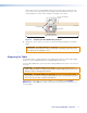
Figure 1. Cable Cubby 300S US/domestic Enclosure The AAP spaces inside the Cable Cubby allow you to customize the enclosure to meet your unique needs. The split AAPs (included) can store almost any type of cable you might encounter. The Extron line of passive AAPs allows you to customize the AAP with almost any kind of pass-through connectivity you may need.
2 1 Figure 3. 3 Cable Cubby 300C Mounting Features • Easy access to cables and AAPs • Compatible with several available AAP modules • Optional retractor available • Compact size • Flexible installation of Extron passive AAPs • Available universal AC outlet is compatible with a variety of AC plug types • UL/c-UL listed and CE compliant • Fits in a range of surface thicknesses. See the table below: Enclosure Minimum Table Thickness Maximum Table Thickness Cable Cubby 300 0.
Installation This section covers the following topics: • Installation Overview • Preparing the Routing Template • Preparing the Table • Installing the Cables and AAPs • Mounting the Cable Cubby Installation Overview Install and set up the Cable Cubby enclosures as follows: 1. If you plan to use a mounting template that has not been prepared, prepare the template (see “Preparing the Routing Template” below). 2.
These strips raise the routing template above the mounting surface to provide room for the collar of the router, protect the mounting surface, and extend the reach of the routing template so that it can be clamped to the edge of the surface. 1/2” x 4” Soft, Finished Lumber HSA 200 CABLE CUBBY 300 HSA 200 USER ACCESS 4 Screws Min. Routing Area CABLE CUBBY 300 USER ACCESS Width of Mounting Surface Figure 4. Preparing the CC 300 Mounting Template 2.
Preparing the Table with a Router Prepare the table with a router as follows: ATTENTION: Potential damage to property. The routing templates for the various Cable Cubby models are not interchangeable. If you use the wrong template, you will cut an improperly sized hole. If you use a larger template than required, the cut will result in gaps in the table surface on either side of the enclosure. ATTENTION: Potential damage to property.
Preparing the Table with a Hole Saw (Cable Cubby 300C Only) Prepare the table with a hole saw as follows: 1. On the tabletop or other installation surface, mark the 6 inch circle, then find and mark the center of the circle. CAUTION: Risk of injury to the eyes. Wear safety glasses when operating the drill. Failure to comply can result in eye injury. 2. Using a portable drill with a 6-inch (or 152 mm) hole saw, carefully cut the opening in the table surface at the desired location (see figure 6).
The simplest way to install the cables and AAPs in the Cable Cubby 300, 600, and 800 is to populate the shelf brackets with split or standard AAPs outside the cubby and then install the populated AAP shelf assembly into the cubby. NOTE: On US/domestic models, the power module takes up two AAP spaces. Cable pass-through AAPs take two, three, or four AAP spaces.Consider the arrangement of the Cable Cubby AAPs when you install them so that you do not waste AAP space.
Installing the Cables Three half-moon cutouts in each set of cable pass-through (split) AAPs loosely channel three cables in the Cable Cubby. Each channel is padded with a split grommet to prevent cable wear. Each channel and each associated split grommet is a different size (see figure 9). Large Small Small Medium Medium Medium Small Large Cable Hole Large Medium Small Figure 9. Large Hole Size 0.625" (1.59 cm) 0.562" (1.43 cm) 0.5" (1.27 cm) Grommet Size 0.453" (1.15 cm) 0.390" (0.99 cm) 0.
Installing the AAPs The split AAPs can be replaced with passive Extron AAPs. Replace a set of split AAPs as follows: 1. Remove the set of split AAPs to be replaced by unscrewing the nuts on the underside of the shelf bracket that fasten the plates to the bracket (see figure 7, on page 7). 2. Cable the AAP(s) before attaching the AAPs to the enclosure. 3. Insert the screws of the AAPs through the holes in the shelf or shelf bracket.
15-pin HD Cable Audio Cable RJ-45 Cable Cable Cubby 300C Surface-Mountable Enclosure for Cables, AAPs, and AC Power Outlet Mounting Surface Screw Clamp Figure 10. Cable Cubby 300C, Installation View 4. From the underside of the table, reinstall the screw clamps on the enclosure at a height at which the clamp will reach the underside of the tabletop. ATTENTION: Potential damage to property. Do not overtighten the Phillips head screws on the screw clamps.
Maintenance and Modifications This section covers the following topics: • Removing and Replacing the Cable Cubby • Replacing Cables or an AAP • Adding an Additional Power Module (CC 600, CC 800) The Cable Cubby can be modified after installation to change cables, to replace an AAP, or to add a second power module. These modifications may require removing the cubby from the table.
Extron Cable Cubby 800 Pins Screw Clamp Phillips Head Screw (Secures AAP Shelf Assembly and Power Module.) Figure 11. Removing the Cubby and its Shelves 4. Lift the enclosure from the table. CAUTION: Risk of personal injury. The flanged edges of the top of the surface enclosure are sharp. Exercise caution when the cubby is not installed in a table to prevent personal injury. ATTENTION: Potential Damage to Property.
ATTENTION: Potential damage to property. Do not overtighten the Phillips head screws on the screw clamps. Overtightening can bend the horizontal flange of the screw clamp. 10. Snugly tighten the Phillips head screws on the screw clamps to secure the enclosure to the surface. 11. Tighten the locking thumbscrews on the screw clamps to lock the clamp in position.
Single Power Module UNSWITCHED Two Power Modules UNSWITCHED 230~50/60Hz 5A Two AAP Space Shelf Three AAP Space Shelf 230~50/60Hz 5A UNSWITCHED 230~50/60Hz 5A Two AAP Space Shelf Figure 12. Cable Cubby 600 with Power Module(s) Figure 13 shows the typical configurations of one and two international power modules installed in a Cable Cubby 800 with no pre-installed power module.
After Before UNSWITCHED UNSWITCHED UNSWITCHED 100-240V/ 5AMAX 100-240V/ 5AMAX 100-240V/ 5AMAX UNSWITCHED UNSWITCHED UNSWITCHED 100-240V/ 5AMAX 100-240V/ 5AMAX 100-240V/ 5AMAX Three AAP Space Shelf Three AAP Space Shelf Four AAP Space Shelf or UNSWITCHED UNSWITCHED 100-240V/ 5AMAX 100-240V/ 5AMAX UNSWITCHED UNSWITCHED 100-240V/ 5AMAX 100-240V/ 5AMAX Two AAP Space Shelf Two AAP Space Shelf Figure 14.
2. If the Phillips head screws on the front and rear of the cubby are blocked by the table, remove the cubby from the table (see “Removing and Replacing the Cable Cubby,” steps 1 through 4, on page 12). 3. Before you add an additional power module, you must make room for the Cable Cubby by eliminating two or three AAP spaces and the AAP shelf brackets that support them.
Reference Information This section covers the following topics: • Cable Cubby Part Numbers • Included Parts • Replacement/Modification Part Numbers • Routing Template Part Numbers • Top Plate Dimensions Cable Cubby Part Numbers Cable Cubby 300S Part Number Cable Cubby 300S US/domestic (black anodized finish) 60-526-01 Cable Cubby 300S (black, AC module optional) 60-712-00 Cable Cubby 300S (brushed aluminum, AC module optional) 60-712-10 Cable Cubby 300C Part Number Cable Cubby 300C/domes
Included Parts The Cable Cubby includes the Cable Cubby Setup Guide and a selection of shelf brackets, cable pass-through AAPs, grommets, and hole plugs that vary depending on the Cable Cubby model. See the table below for included parts: Large Small Small Medium Medium Medium Small Large AAP Cable Pass Through Left 70-270-01 AAP Cable Pass Through Left Middle 70-269-01 Large AAP Cable Pass Through Right Middle 70-268-01 AAP Cable Pass Through Right 70-267-01 AAP Shelf Brackets Model 2 Pos.
Top Plate Dimensions There are two preferred and recommended methods for cutting the table: using the appropriate metal routing template (see figure 19 below and Installation on page 4), and using a router or a hole saw (Cable Cubby 300C only). CABLE CUBBY 300 USER ACCESS HSA 200 USER ACCESS HSA 200 CABLE CUBBY 300 Figure 17.
Cut-Out Template for Cut-Out Template for Cable Cubby 300S Cable Cubby 300C 5.13" (13.0 cm) 4.625" (11.7 cm) 6.47" (16.4 cm) 6.5" Dia. (16.51 cm) SURFACE CUT-OUT AREA = 4.625" (11.7 cm) x 5.97" (15.2 cm) 5.97" (15.2 cm) 6.0" Dia. (15.24 cm) SURFACE CUT-OUT AREA = 6.0" Dia. Cut surface material out along this line. 0.5" (1.3 cm) Top Panel User Access Cut-Out Radius: 0.25" (0.6 cm) User Access TEMPLATE IS NOT FULL SIZE. TEMPLATE IS NOT FULL SIZE. Figure 18.
Extron Warranty Extron Electronics warrants this product against defects in materials and workmanship for a period of three years from the date of purchase.