User’s Manual DVI-RGB 150 DVI to Analog RGB Video Interface www.extron.com Extron Electronics, USA Extron Electronics, Europe Extron Electronics, Asia Extron Electronics, Japan 1230 South Lewis Street Anaheim, CA 92805 USA 714.491.1500 Fax 714.491.1517 Beeldschermweg 6C 3821 AH Amersfoort The Netherlands +31.33.453.4040 Fax +31.33.453.4050 135 Joo Seng Road, #04-01 PM Industrial Building Singapore 368363 +65.6383.4400 Fax +65.6383.
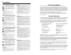
Precautions Safety Instructions • English This symbol is intended to alert the user of important operating and maintenance (servicing) instructions in the literature provided with the equipment. This symbol is intended to alert the user of the presence of uninsulated dangerous voltage within the product’s enclosure that may present a risk of electric shock. Caution Read Instructions • Read and understand all safety and operating instructions before using the equipment.
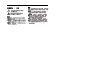
Chapter One • Introduction .................................................... 1-1 Chapter Two • Installation and Operation ................... 2-1 Installation Overview ............................................................... 2-2 Mounting the Interface .......................................................... 2-2 Tabletop placement ............................................................... 2-2 Rack mounting .......................................................................
Table of Contents, cont'd DVI-RGB 150 1 Chapter One Introduction 68-1247-01 Rev. A 07 06 All trademarks mentioned in this manual are the properties of their respective owners.
Introduction The Extron DVI-RGB 150 DVI to analog RGB video interface converts DVI digital video to analog RGB video. The interface accepts a single link of digital-only Digital Visual Interface (DVI-D) video from a computer, or other digital video source device, on a standard 29-pin female DVI-I connector. The interface outputs analog RGBHV, RGBS, or RGsB video on female BNC connectors. The interface also buffers the DVI input and loops it through on a DVI connector for use by a local monitor (figure 1-1).
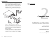
Installation and Operation Installation Overview 6" Deep Rack Shelf 1/2 Rack Width Front False Faceplate To install and set up an Extron DVI-RGB 150 for operation, follow these steps: 1 Turn off all of the equipment. Ensure that the video sources and the output display are all turned off and disconnected from the power source. 2 Mount the interface. See Mounting the Interface, below. 3 Connect the cables. See Rear Panel Connections and Controls in this chapter.
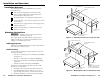
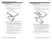
Installation and Operation, cont’d Under-desk mounting Mount the unit under a desk or podium using the optional Extron MBU 125 under desk mounting kit (part #70-077-01) as follows: Through-desk mounting Mount the unit through a desk or podium using the optional Extron MBD 129 through desk mounting kit (part #70-077-02) as follows: 1. If rubber feet were previously installed on the bottom of the unit, remove them. 1. If rubber feet were previously installed on the bottom of the unit, remove them. 2.
Installation and Operation, cont’d d Slide the device in or out until it is in the desired position. Tighten the screws installed in step 2. If the screws are inaccessible to a screwdriver: a. Mark the location of the brackets relative to the screws. e d. Replace the unit inside the surface (step 6). Rear Panel Connections and Controls Input connector — Connect a single link of direct digital video to this 25-pin DVI-D connector (figure 2-5) using the included cable.
Installation and Operation, cont’d Front Panel Controls and Indicator 8 9 Operation After the DVI-RGB 150 and its connected devices are powered up, the system is fully operational. If any problems are encountered, verify that the cables are routed and connected properly.
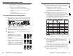
Installation and Operation, cont’d DVI Connector Pin Assignments Figure 2-7 and the table below define the DVI pin assignments. 9 1 8 17 24 Female Connector 8 1 24 17 Male Connector Figure 2-7 — DVI connectors DVI signals run at a very high frequency and are especially prone to bad video connections, too many adapters, or excessive cable length. To avoid the loss of an image or jitter, follow these guidelines: • Do not exceed 16.
Reference Information Resolution selector resolutions and rates Specifications Setting 0 1 2 3 4 5 6 7 8 9 A B C D E F Video N The DVI-RGB 150 converts a single link DVI signal to an analog RGB signal. N Using an adaptor (the Extron HDMI to DVI-D adapter, part #26-616-01), the DVI-RGB 150 can accept HDMI signals. It converts HDMI digital RGB signals, but does not support the HDMI digital component (YCrCb) signal format. Video input and loop-through Number/signal type .....................
Reference Information, cont’d General Part Numbers Power ............................................. 100 VAC to 240 VAC, 50/60 Hz, 25 watts, internal, autoswitchable. Temperature/humidity ................ Storage: -40 to +158 °F (-40 to +70 °C) / 10% to 90%, noncondensing Operating: +32 to +122 °F (0 to +50 °C) / 10% to 90%, noncondensing Rack mount ....................................
Reference Information A-6 DVI-RGB 150 • Reference Information