User’s Guide VSC 700/900 SDI Output Card 70-065-02 Upgrade Kit 68-735-01 Rev.
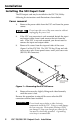
Installation Installing the SDI Ouput Card The SDI output card may be installed in the VSC 700/900 by following the instructions and illustrations shown below. Cover removal Remove the power cable from the VSC and from the power source. 1. Do not open the cover of the scan converter without unplugging the power cord. 2. If the VSC scan converter is rack mounted, detach the input and output cables from it and remove the unit from the rack.
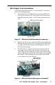
SDI Output Card installation After following the instructions in “Cover removal” to remove the cover, do the following: 1. Locate the SDI card standoff located near the middle rear (VSC 900) or left rear (VSC 700) portion of the main circuit board (looking from above with the front panel nearest to you). SDI card connector opening SDI card standoff Figure 2 — SDI card standoff and connector opening 2.
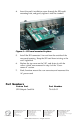
. Insert the card’s installation screw through the SDI card’s mounting hole, and gently tighten it into the standoff. Figure 4 — SDI card mounted in place 5. Install the SDI connector’s hex nut from the outside of the rear panel opening. Keep the SDI card from twisting as the nut is tightened. 6. Replace the top cover on the VSC, and fasten it with the screws which were removed in step 3 of the “Cover removal” section. 7. Rack/furniture mount the scan converter, and reconnect the AC power cord.