User Guide DVI & HDMI Extenders DTP HDMI 301 HDMI Twisted Pair Extender 68-2156-01 Rev.
Safety Instructions • English Warning This symbol is intended to alert the user of important operating and maintenance (servicing) instructions in the literature provided with the equipment. Power sources • This equipment should be operated only from the power source indicated on the product. This equipment is intended to be used with a main power system with a grounded (neutral) conductor. The third (grounding) pin is a safety feature, do not attempt to bypass or disable it.
FCC Class A Notice This equipment has been tested and found to comply with the limits for a Class A digital device, pursuant to part 15 of the FCC Rules. Operation is subject to the following two conditions: 1. This device may not cause harmful interference. 2. This device must accept any interference received, including interference that may cause undesired operation.
Conventions Used in this Guide In this user guide, the following are used: CAUTION: NOTE: A caution indicates a potential hazard to equipment or data. A note draws attention to important information. TIP: A tip provides a suggestion to make working with the application easier. WARNING: A warning warns of things or actions that might cause injury, death, or other severe consequences. Copyright © 2011 Extron Electronics. All rights reserved.
Contents Introduction............................................. 1 Reference Information........................... 12 About this Guide.............................................. 1 About the DTP HDMI 301 Tx/Rx Transmitter and Receiver.................................................... 1 TP Cable Advantages.................................... 2 Control Communications.............................. 2 Features............................................................ 2 Specifications.................
DTP HDMI 301 • Contents vi
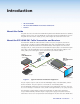
Introduction • About this Guide • About the DTP HDMI 301 Transmitter and Receiver • Features About this Guide This guide describes the Extron DTP HDMI 301 High Definition Multimedia Interface (HDMI™) Extender, which consists of a DTP HDMI 301 Tx transmitter and a DTP HDMI 301 Rx receiver. This guide describes how to install, operate, and configure the transmitter and receiver.
TP Cable Advantages Twisted pair cable is much smaller, lighter, more flexible, and less expensive than coaxial or HDMI cable. These transmitter and receiver twisted pair (TP) products make cable runs simpler and less cumbersome. Termination of the cable with RJ-45 connectors is simple, quick, and economical. NOTE: Do not use Extron UTP23SF-4 Enhanced Skew-Free™ AV UTP cable or STP201 cable to link the transmitter and receiver. The DTP HDMI 301 Tx/Rx does not work properly with these cables.
Installation and Operation This section describes the installation and the operation of the DTP HDMI 301 Tx/Rx Extender, including: • Mounting the Transmitter or Receiver • Connections • Operation Mounting the Transmitter or Receiver CAUTION: Installation and service must be performed by authorized personnel only. Mounting instructions and the applicable optional hardware can be found in the “Reference Information“ section.
b Audio connector — If desired, plug an analog audio input into the transmitter via this stereo mini jack connector. NOTES: • The analog audio input on this connector is in addition to the digital audio that is embedded in the HDMI input. Tip (+) • See the figure at right to identify the tip, ring, Ring (-) and sleeve when you are making connections for the transmitter from existing audio cables. A mono audio connector consists of the tip Sleeve ( ) and sleeve. A stereo audio connector consists 3.
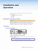
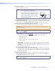
Receiver Connections DTP HDMI 301 Rx Rear Panel POWER 12V 0.6 A MAX IN SIG ANALOG AUDIO . 10 Front Fro ont Panel OUTPUTS LINK AUDIO DTP IN L 7 6 RS-232 IR Tx Rx Tx Rx R 8 DTP HDMI 301 Rx 9 Figure 3. DTP HDMI 301 Rx Rear Panel Connectors f DTP and Analog Audio Input RJ-45 connectors — Connect one end of the one or two separate TP cables from the transmitter output connectors to these RJ-45 female connectors.
h Audio output connector — This 5-pole, 3.5 mm captive screw connector outputs the transmitted, unamplified, line level analog audio. Connect an audio device, such as an audio amplifier or powered speakers. See figure 4 to properly wire a captive screw output connector. Use the supplied tie-wrap to strap the audio cable to the extended tail of the connector. NO GROUND HERE Tip Ring R Figure 4.
Pin Assignments and Wiring HDMI connector Figure 5 defines the pinout for the HDMI connector.
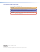
TP cable termination Figure 7 details the recommended termination of TP cables with RJ-45 connectors in accordance with either the TIA/EIA T 568A or the TIA/EIA T 568B wiring standard. Side Pins: RJ-45 Connector 12345678 TIA/EIA T 568 A Pin Wire color Insert Twisted Pair Wires TIA/EIA T 568 B Wire color 1 White-green White-orange 2 Orange Green 3 White-orange White-green 4 Blue Blue 5 White-blue White-blue 6 Orange Green 7 White-brown White-brown 8 Brown Brown Figure 7.
Terminating shielded cable The Tx and Rx each include two shielded RJ-45 connectors and a length of self-adhesive shielded tape that you can use to make the STP cables that connect the transmitter and receiver. NOTE: Extron supplies the connectors and the shielded tape. You must supply the CAT 5e, CAT 6, or CAT 6a STP cable. Terminate the STP cable as follows: 1. Peel back the cable shielding (see figure 8) from the end of the cable the length of the RJ-45 connector body (approximately 7/8 inch [2.
Power supply wiring NOTES: • Only one power supply is required. A single power supply connected to either unit in the pair powers both units. • A power supply is included with each transmitter. Figure 11 shows how to wire the connector. Use the supplied tie-wrap to strap the power cord to the extended tail of the connector. Smooth A Ridges A SECTION A–A Power Supply Output Cord Tie Wrap 3 5 Captive Screw Connector Figure 11.
RS-232 and IR connector wiring Figure 12 shows how to wire the RS-232 connector. Connected RS-232 and IR Device Pins IR Tx Rx RS-232 Tx Rx Tx/Rx Pins Transmit pin on connected unit Receive pin on connected unit Ground Transmit pin on connected unit Receive pin on connected unit Figure 12. RS-232 Connector Wiring NOTE: The length of exposed wires is important. The ideal length is 3/16 inch (5 mm). See the NOTE on page 6 for details.
Reference Information This section discusses the specifications, part numbers, and accessories for the DTP HDMI 301 Tx/Rx transmitter and receiver. Topics that are covered include: • Specifications • Part Numbers and Accessories • Mounting the Transmitter or Receiver Specifications NOTES: • This product consists of a transmitter (DTP HDMI 301 Tx) and a receiver (DTP HDMI 301 Rx), sold separately, with twisted pair cables linking the transmitter and receiver.
Audio input Number/signal type ������������������������ Connectors ������������������������������������ Impedance ������������������������������������� Nominal level ��������������������������������� Maximum level ������������������������������� 1 PC level stereo, unbalanced (1) 3.5 mm stereo jack, 2 channel; tip (L), ring (R), sleeve (ground) >10k ohms, DC coupled -10 dBV (316 mVrms) +7 dBV (unbalanced) NOTE: 0 dBu = 0.
General Power supply ���������������������������������� External Input: 100-240 VAC, 50-60 Hz Output: 12 VDC, 1 A, 12 watts Power consumption ����������������������� 7.0 watts, 12 VDC, total, for both transmitter and receiver NOTE: Each transmitter or receiver can be powered either locally by an external power supply or remotely by receiver or transmitter on the other end of the CAT 5/5e/6 cable.
Part Numbers and Accessories Transmitter/Receiver Pair Part Numbers NOTE: The Tx/Rx is comprised of the transmitter and receiver pair, which are purchased separately. DTP HDMI 301 Model Part Number DTP HDMI 301 Tx transmitter 60-1212-12 DTP HDMI 301 Rx receiver 60-1212-13 Included Parts These items are included with in each DTP HDMI 301 transmitter and receiver: Included parts Part Number DTP HDMI 301 Tx Transmitter 12 VDC, 1 A external power supply with 3.
Mounting Accessories Mounting kit Part Number RSF 123 3.5-inch deep 1U rack shelf kit (transmitter only) 60-190-20 RSB 123 3.5-inch deep 1U rack shelf (transmitter only) 60-604-21 RSU 126 6-inch deep 1U universal rack shelf kit 60-190-10 RSB 126 6-inch deep 1U basic rack shelf 60-604-11 RSU 129 9.5-inch deep 1U universal rack shelf kit 60-190-01 RSB 129 9.
Extron Warranty Extron Electronics warrants this product against defects in materials and workmanship for a period of three years from the date of purchase.