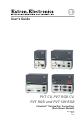
User’s Guide PVT CV, PVT RGB CV, PVT RGB and PVT SW RGB PoleVault™ Twisted Pair Transmitters (Rack Mount Models) 68-1310-01 Rev.
Precautions Safety Instructions • English This symbol is intended to alert the user of important operating and maintenance (servicing) instructions in the literature provided with the equipment. This symbol is intended to alert the user of the presence of uninsulated dangerous voltage within the product’s enclosure that may present a risk of electric shock. Caution Read Instructions • Read and understand all safety and operating instructions before using the equipment.
Precautions ᅝܼ乏ⶹ 噝 Ё᭛ 䖭Ͼヺোᦤ⼎⫼᠋䆹䆒⫼᠋ݠЁ ⱘ᪡㓈ᡸ䇈ᯢDŽ 䖭Ͼヺো䄺ਞ⫼᠋䆹䆒ᴎݙᲈ 䴆ⱘॅ䰽⬉य़ˈ᳝㾺⬉ॅ䰽DŽ ⊼ᛣ 䯙䇏䇈ᯢк 噝 ⫼᠋Փ⫼䆹䆒ࠡᖙ乏䯙䇏ᑊ⧚㾷 ᳝ᅝܼՓ⫼䇈ᯢDŽ ֱᄬ䇈ᯢк 噝 ⫼᠋ᑨֱᄬᅝܼ䇈ᯢкҹᇚᴹՓ⫼DŽ 䙉ᅜ䄺ਞ 噝 ⫼᠋ᑨ䙉ᅜѻક⫼᠋ᣛफϞⱘ᠔᳝ ᅝܼ᪡䇈ᯢDŽ 䙓ܡ䗑ࡴ 噝 ϡ㽕Փ⫼䆹ѻકॖଚ≵᳝㤤ⱘᎹ 䗑ࡴ䆒ˈҹ䙓ॅܡ䰽DŽ 䄺ਞ ⬉⑤ 噝 䆹䆒া㛑Փ⫼ѻકϞᷛᯢⱘ⬉⑤DŽ 䆒ᖙ⫼᳝ ഄ㒓կ⬉㋏㒳կ⬉DŽϝᴵ㒓˄ഄ㒓˅ᰃᅝ䆒ᮑˈϡ㛑ϡ ⫼䏇䖛DŽ ᢨᥝ⬉⑤ 噝 ЎᅝܼഄҢ䆒ᢨᥝ⬉⑤ˈ䇋ᢨᥝ᠔᳝ ৢḠ䴶⬉⑤ⱘ⬉⑤㒓ˈӏԩࠄᏖ⬉㋏㒳 ⬉⑤㒓DŽ ⬉⑤㒓ֱᡸ 噝 ཹᏗ㒓ˈ 䙓ܡ㹿䏽䏣ˈ䞡⠽य़DŽ 㓈ᡸ 噝 ᠔᳝㓈ׂᖙ乏⬅䅸䆕ⱘ㓈ׂҎਬ䖯㸠DŽ 䆒 䚼≵᳝⫼᠋ৃҹᤶⱘ䳊ӊDŽЎ䙓⦄ߎܡ㾺⬉ॅ ϡ㽕㞾Ꮕ䆩ᠧᓔ䆒Ⲫᄤ㓈ׂ䆹䆒DŽ 䗮亢ᄨ 噝 ᳝ѯ䆒ᴎϞ᳝䗮亢ῑᄨˈᅗӀᰃ
This page was deliberately left blank.
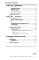
Table of Contents Chapter One • Introduction ..................................................... 1-1 About the PVT Transmitters .................................................... 1-2 Transmission distance . ........................................................... 1-2 About the PVT CV ................................................................... 1-3 About the PVT RGB ................................................................ 1-3 About the PVT RGB CV .......................................
Table of Contents, cont'd This page was deliberately left blank.
PVT Series (Rack Mount Models) 1 Chapter One Introduction About the PVT Transmitters Application Diagram
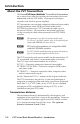
Introduction About the PVT Transmitters The Extron ���������������������� PVT Series (PoleVault™ Twisted Pair Transmitters) are a series of cost effective twisted pair transmitters that work exclusively with the PVS 204SA, a four-input twisted pair switcher with a built in power amplifier. PVT transmitters can transmit composite video and stereo audio or high resolution video (RGB) and stereo audio to the PVS 204SA switcher over CAT 5 twisted pair cable, up to a distance of 100 feet.
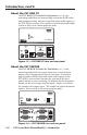
About the PVT CV The PVT CV Twisted Pair Transmitter is a 1/8 rack mounting model that can transmit composite video and stereo audio to the PVS 204SA switcher. This model can also be mounted under a desk or shelf, or on certain projector poles.
Introduction, cont’d About the PVT RGB CV The PVT RGB CV Twisted Pair Transmitter is a 1/4 rack mounting model that can transmit high resolution (RGB) video and composite video, and two associated stereo audio signals to the PVS 204SA switcher. This model can also be mounted under a desk or shelf, or on certain projector poles.
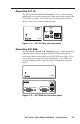
Application Diagram Extron SI 26X Extron SI 26X Two-way, Open Back Ceiling Speakers – 1 Pair Option Two-way, Open Back Ceiling Speakers – 1 Pair Extron SPK 18 - 25' Cable Included Extron PCM 240 Projector Drop Ceiling Mount Extron PMP Projector Mount Pole Extron PVS 204SA PoleVault ™ Switcher D Ohms 4/8 OUTPUTS AMPLIFIE R L GROUND NOTSHORT DO OR OUTPUTS! 17TT SPEAKER LISTED AUDIO/VIDEO US APPARATUS MLC/IR 12V IR RS-232 Rx Tx DC VOL E 10V VOL/MUT ® A B C IN RGB O U T P U T S VIDE
Introduction, cont'd This page was deliberately left blank.
PVT Series (Rack Mount Models) 2 Chapter Two Installation UL/Safety Requirements Installing the PVT Twisted Pair Transmitters Connections and Settings
Installation UL/Safety Requirements The Underwriters Laboratories (UL) requirements listed below pertain to the safe installation and operation of the transmitters. Important safety instructions 2-2 1. Read these instructions. 2. Keep these instructions. 3. Heed all warnings. 4. Follow all instructions. 5. Do not use this apparatus near water. 6. Clean only with a dry cloth. 7. Do not block any ventilation openings. Install in accordance with the manufacturer’s instructions. 8.
Installing the PVT Twisted Pair Transmitters The PVT CV is a 1/8 rack shelf mountable transmitter, and the PVT RGB, PVT RGB CV, and PVT SW RGB are 1/4 rack shelf mountable transmitters. Each of the four models can be mounted under a desk or shelf, or on to certain projector mounts, and are also suitable for tabletop use. Tabletop use The PVT comes with self-adhesive rubber feet attached to the four corners of the bottom. Set the PVT on a horizontal surface.
Installation, cont’d To rack mount a PVT transmitter, do the following: 1. If installed, remove the feet from the bottom of the PVT. 2. Mount the PVT using two 4-40 x 3/16" screws in opposite (diagonal) corners to secure the PVT to the shelf. 3. Install blank panel(s) or other unit(s) to the rack shelf.
Furniture mounting Use the optional mounting kit (MBU 123, under desk mounting kit, part #70-212-01) to mount the PVT as follows: 1. If installed, remove the feet from the bottom of the PVT. 2. Attach the mounting brackets to the PVT with the machine screws provided (figure 2-3). Figure 2-3 — Mounting the PVT under a desk 3. Hold the PVT with the attached brackets against the underside of the mounting surface. Mark the bracket screw hole locations on the mounting surface. 4.
Installation, cont’d Connections and Settings Do not connect these devices to a computer data or telecommunications network. Do not connect these devices to an MTP system. N Front panel features The front panel features are the same for the PVT CV, PVT RGB, and PVT RGB CV. The PVT SW RGB features are unique to that model.
a b c d Dual color power LED — This LED lights amber when power only (no signal) is applied to the PVT, and green when power and a signal are both present. Auto switch LED (PVT SW RGB only) — This LED lights green when the unit is in auto switch mode. AUTO SWITCH Input selection button with LED (PVT SW RGB only) — Press these buttons to select (switch) between inputs 1 and 2. The associated LEDs lights green when the input has an active video signal connected, and amber when there is no signal present.
Installation, cont’d Rear panel features For all PVT rack mount models, the input connectors and the output connectors are on the rear panel (see figure 2-5).
a b Composite video input (CV and RGB CV models) — To input a composite video signal from a suitable source, connect a male RCA plug to this yellow female RCA jack. Audio (left and right) input (CV and RGB CV models) — For unbalanced left and right audio input, insert male RCA plugs from the audio source, into these two female RCA jacks (white = left, red = right).
Installation, cont’d Clip Down Side Pins 1 2 3 4 5 6 7 8 TP Cable and CAT 5 connector Composite Video and Audio signal 568A Wire color Pin RJ-45 connector 1 White-green Video + 2 Green Video – 3 White-orange + 5 VDC 4 Blue Audio L + 5 White-blue Audio L – 6 Orange GND 7 White-brown Audio R + 8 Brown Audio R – 12345678 Twisted pairs 1&2 3&6 4&5 7&8 Figure 2-7 — Wiring the twisted pair composite video and audio cable PVT CV VIDEO IN PVT RGB CV PVS 204SA AUDIO IN L R V
e RGB video input (RGB CV, RGB, and SW RGB models) — Connect a computer video source to this 15-pin HD connector for high resolution RGB video input. ä RGB cable A output (RGB CV, RGB, and SW RGB models) — ã RGB cable B output (RGB CV, RGB, and SW RGB models) — Using TP cable, connect this RJ-45 female output port, labeled "RGB A out", to one of the two input ports (labeled 1A and 2A) on the PVS 204SA switcher.
Installation, cont’d PVT SW RGB PVT RGB TP Cable from output A PVS 204SA RGB A OUT INPUT 2 RGB 1A MONITOR OUT POWER RGB B OUT TP Cable from output B PIN 1 — IN 1 PIN 4 — IN 2 PIN 5 — GND RGB A OUT CONTACT 2A I N P U T S MONITOR OUT RGB B OUT Rear Panel 1B Rear Panel REMOTE TPINPUT Cable1 from output A 2B 12V 3A MAX TP Cable from output B RGB Input Connectors on Rear Panel of PVS 204SA Figure 2-11 — Connecting RGB outputs A and B to the PVS 204SA switcher g Monitor output (RGB and
PVT Series (Rack Mount Models) A Appendix A Reference Material Specifications Part Numbers Optional Accessories
Reference Material Specifications N These transmitters are compatible only with the Extron PVS 204SA. They are not compatible with other models of twisted pair receivers. Video — RGB (RGB models) Gain ................................................. Unity Video input and loop-through — RGB (RGB models) Number/signal type...................... 1 VGA-UXGA RGBHV, RGBS (2 for PVT SW RGB, and 1 buffered loop through) Connectors......................................
Impedance . .................................... 75 ohms Return loss ..................................... <-30 dB @ 10 MHz DC offset (max. allowable)........... 100 mV Video output — composite video (CV models) Number/signal type...................... 1 analog proprietary signal Connectors ..................................... 1 female RJ‑45 Sync — composite video (CV models) Standards......................................... NTSC 3.58, NTSC 4.43, PAL, SECAM Audio input Number/signal type...............
Reference Material, cont’d Enclosure dimensions PVT CV 1/8 rack Versa Tools..... 1.7" H x 2.2" W x 3.0" D 4.3 cm H x 5.6 cm W x 7.6 cm D PVT RGB, PVT SW RGB, PVT RGB CV 1/4 rack Versa Tools..... 1.7" H x 4.3" W x 3.0" D 4.3 cm H x 10.9 cm W x 7.6 cm D (Depths excludes connectors.) Product weight............................... 1 lbs (0.5 kg). Shipping weight............................. 2 lbs (1 kg) Vibration . .......................................
Optional Accessories Item Part number MBU 123, under desk mounting kit 70-212-01 MBB 100, back of rack mounting kit 70-367-01 RSF 123, 3.5" deep rack shelf mounting kit 60-190-20 RSB 123, 3.5" deep basic rack shelf mounting kit 60-604-20 RSU 129, 9.5" deep rack shelf mounting kit 60-190-01 RSB 129, 9.
Reference Material, cont’d This page was deliberately left blank.
FCC Class A Notice Note: This equipment has been tested and found to comply with the limits for a Class A digital device, pursuant to part 15 of the FCC Rules. These limits are designed to provide reasonable protection against harmful interference when the equipment is operated in a commercial environment. This equipment generates, uses and can radiate radio frequency energy and, if not installed and used in accordance with the instruction manual, may cause harmful interference to radio communications.
www.extron.com Extron Electronics, USA 1230 South Lewis Street Anaheim, CA 92805 800.633.9876 714.491.1500 FAX 714.491.1517 Extron Electronics, Europe Beeldschermweg 6C 3821 AH Amersfoort, The Netherlands +800.3987.6673 +31.33.453.4040 FAX +31.33.453.4050 Extron Electronics, Asia 135 Joo Seng Rd. #04-01 PM Industrial Bldg., Singapore 368363 +800.7339.8766 +65.6383.4400 FAX +65.6383.4664 © 2007 Extron Electronics. All rights reserved.