
User's Manual


2-9
PVT Series (Rack Mount Models) • Installation
a
Composite video input (C� and RGB C� models) —
To input a composite video signal from a suitable source,
connect a male RCA plug to this yellow female RCA jack.
b
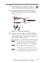
Audio (left and right) input (C� and RGB C� models) —
For unbalanced left and right audio input, insert male RCA
plugs from the audio source, into these two female RCA jacks
(white = left, red = right).
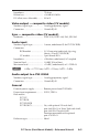
Sleeve (Gnd )
Right Channel
(Red Jacket)
Left Channel
(White Jacket)
Tip (Signal)
Tip (+)
Sleeve ( )
Figure 2-6 — RCA audio connectors
c
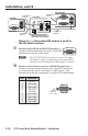
Composite video/audio output (C� and RGB C� models) —
For composite video and audio output, using TP cable, connect
this RJ-45 female output port to one of the two composite
video RJ-45 input connectors (labeled 3 and 4), on the rear panel
of the PVS 204SA switcher (see figure 2-8).
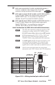
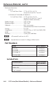
Cable termination for composite video and audio transmission
N
The PVT cable termination method is specific for PVT
transmitters working with the PVS 204SA switcher.
DO NOT connect these devices to an MTP system.
N
RJ-45 termination with CAT 5, CAT 5e, CAT 6, and
Skew-Free A/V UTP cable must comply with the
TIA/EIA T 568A wiring standards for all connections.
N
For composite video signals, the RJ-45 connector must
be wired exactly as shown in figure 2-7, so that the input
video and audio signals are transmitted correctly.