User’s Manual CAUTION Do not connect this device to a computer data or telecommunications network. TP Transmitters Family www.extron.com Extron Electronics, USA 1230 South Lewis Street Anaheim, CA 92805 800.633.9876 714.491.1500 FAX 714.491.1517 Extron Electronics, Europe Beeldschermweg 6C 3821 AH Amersfoort, The Netherlands +800.3987.6673 +31.33.453.4040 FAX +31.33.453.4050 Extron Electronics, Asia 135 Joo Seng Rd. #04-01 PM Industrial Bldg., Singapore 368363 +800.7339.8766 +65.6383.4400 FAX +65.
Precautions Safety Instructions • English This symbol is intended to alert the user of important operating and maintenance (servicing) instructions in the literature provided with the equipment. This symbol is intended to alert the user of the presence of uninsulated dangerous voltage within the product's enclosure that may present a risk of electric shock. Caution Read Instructions • Read and understand all safety and operating instructions before using the equipment.
ᅝܼ乏ⶹ 噝 Ё᭛ 䖭Ͼヺোᦤ⼎⫼᠋䆹䆒⫼᠋ݠЁ ⱘ᪡㓈ᡸ䇈ᯢDŽ 䖭Ͼヺো䄺ਞ⫼᠋䆹䆒ᴎݙᲈ 䴆ⱘॅ䰽⬉य़ˈ᳝㾺⬉ॅ䰽 ⊼ᛣ 䯙䇏䇈ᯢк 䯙䇏䇈ᯢк 噝 ⫼᠋Փ⫼䆹䆒ࠡᖙ乏䯙䇏ᑊ⧚㾷 ᳝ᅝܼՓ⫼䇈ᯢDŽ ֱᄬ䇈ᯢк ֱᄬ䇈ᯢк 噝 ⫼᠋ᑨֱᄬᅝܼ䇈ᯢкҹᇚᴹՓ⫼DŽ 䙉ᅜ䄺ਞ 噝 ⫼᠋ᑨ䙉ᅜѻક⫼᠋ᣛफϞⱘ᠔᳝ ᅝܼ᪡䇈ᯢDŽ 䙓ܡ䗑ࡴ 噝 ϡ㽕Փ⫼䆹ѻકॖଚ≵᳝㤤ⱘᎹ 䙓ܡ䗑ࡴ 䗑ࡴ䆒ˈҹ䙓ॅܡ䰽DŽ 䄺ਞ ⬉⑤ 噝 䆹䆒া㛑Փ⫼ѻકϞᷛᯢⱘ⬉⑤DŽ 䆒ᖙ⫼᳝ ⬉⑤ ഄ㒓կ⬉㋏㒳կ⬉DŽϝᴵ㒓˄ഄ㒓˅ᰃᅝ䆒ᮑˈϡ㛑ϡ ⫼䏇䖛DŽ ᢨᥝ⬉⑤ 噝 ЎᅝܼഄҢ䆒ᢨᥝ⬉⑤ˈ䇋ᢨᥝ᠔᳝ ᢨᥝ⬉⑤ ৢḠ䴶⬉⑤ⱘ⬉⑤㒓ˈӏԩࠄᏖ⬉㋏㒳 ⬉⑤㒓DŽ ⬉⑤㒓ֱᡸ 噝 ཹᏗ㒓ˈ 䙓ܡ㹿䏽䏣ˈ䞡⠽य़DŽ ⬉⑤㒓ֱᡸ 㓈ᡸ 噝 ᠔᳝㓈ׂᖙ乏⬅䅸䆕ⱘ㓈ׂҎਬ䖯㸠DŽ 䆒 㓈ᡸ 䚼≵᳝⫼᠋ৃҹᤶⱘ䳊ӊDŽЎ䙓⦄ߎܡ㾺⬉ॅ ϡ㽕㞾Ꮕ䆩ᠧᓔ䆒Ⲫᄤ㓈ׂ䆹䆒DŽ
Table of Contents Chapter 1 • Introduction .......................................................... 1-1 About the TP Transmitters ................................................ 1-2 Features ...................................................................................... 1-3 TP T 15HD A transmitter ....................................................... 1-3 TP T 15HD AV transmitter ..................................................... 1-4 TP T 468 transmitter .......................................
Table of Contents, cont’d Front Panel Control and Indicators ............................ 2-29 Troubleshooting ................................................................... 2-30 TP Transmitters If the image does not appear ............................................. 2-30 If the image is not displayed correctly ............................... 2-31 If the receiver’s Manual/Auto LED flashes .......................... 2-31 Appendix A • Specifications, Accessories, and Part Numbers ...................
Introduction, cont’d Introduction About the TP Transmitters Extron’s Twisted Pair (TP) transmitters provide long-distance distribution of RGB video, component video, S-video, composite video, and stereo audio over Extron’s Skew-Free™ A/V UTP cable or standard Category (CAT) 5 unshielded twisted pair (UTP), shielded twisted pair (STP), or foil shielded twisted pair (FTP) cable. The minimum reliable transmission distance to all receivers, with the exception of the TP R 15HD A, is 50 feet (15.2 meters).
Introduction, cont’d TP T 15HD AV transmitter Video input Computer video — Accepts computer analog video on a 15-pin HD female connector. With an adapter cable, the 15HD connector can accept a Macintosh video, 13W3 video, or RGBHV, RGBS, RGsB, component video, S-video, or single source composite video input. Composite video — Accepts NTSC, PAL, and SECAM composite video on an RCA jack. Alternately, the composite video channel can support digital audio.
Introduction, cont’d TP Transmitters 2 Chapter Two Installation and Operation Installation Front Panel Control and Indicators Troubleshooting 1-6 Extron TP Transmitters • Introduction
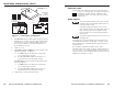
Installation and Operation, cont’d Installation and Operation Installation 8 CAUTION Installation and service must be performed by authorized personnel only. The TP T 468 must be used with a UL approved electrical box. Connect power cords to the TP receiver, the TP transmitter, and turn on the video source(s) and the output display(s). All TP transmitters include a 15 V external power supply.
Installation and Operation, cont’d Lift cover straight up. CO Component, S-video, RGB Composite MP UT ID PIN 4 ID PIN 11 ER 1 1 INPU T BU 1 1 LO FF ER ED CA L MO HNITO SH IFT R TP T 15 1 1 1 1 HD Component, S-video, Composite A RGB J1 J2 1 1 1 1 1 1 1 1 J12 J11 U31 TP T BNC DA4 TP T 15HD A and TP T 15HD AV Figure 2-1 — Video jumper configuration 2.
Installation and Operation, cont’d Remove the two screws on each side and the screw on top of the cover (figure 2-2). Remove (5) Screws Wire Pair Wire Pair 3&6* 7&8 1 TP T 15HD AV AU Lift Cover straight up DIO CO MP UT INPU ER ID PIN J6 J7 4 ID PIN T 11 BU FF LO CA ER Tabletop use Four self-adhesive rubber feet are included with the unit. For tabletop use, affix one foot at each corner of the bottom of the transmitter, and place the unit in the desired location.
Installation and Operation, cont’d 5. Attach the rack shelf to the rack using the supplied bolts. 1U Universal Rack Shelf (2) 4-40 x 3/16" Screws Use 1 mounting hole on each side of the unit to attach it to the RSM 100. To mount the transmitter under a desk, podium, or table top, 1. If rubber feet were previously attached to the bottom of the unit, remove them. 2. Remove the two screws from one side of the unit. Retain the screws for possible later reassembly. 3.
Installation and Operation, cont’d Through-desk mounting Mount the transmitter through a desk or table, using the optional through-desk mounting kit (part #70-077-02). c. Tighten the screws. d. Replace the unit inside the surface (repeat step 4).
Installation and Operation, cont’d 9 10 11 Install the desired AAPs on the transmitter. See “Mounting the optional AAP devices,” later in this chapter. Mount the transmitter into the electrical box or to the mud ring. If using a wall box, see “Mounting the transmitter to the mud ring or wall box,” later in this chapter. Preparing the site and installing the mud ring or wall box The TP T 468 is mounted into a wall or furniture. Follow the instructions appropriate to the mounting option you have selected.
Installation and Operation, cont’d 5. If you are using a wall box, feed cables through the wall box punch-out holes, and secure them with cable clamps to provide strain relief. 6. Exposed cable shields (braids or foil) are potential sources of short circuits. Trim back and/or insulate shields with heat shrink (figure 2-7). 7. If you are using a mud ring, follow the directions, if any, that came with the mud ring to attach the clips that fasten it to the wall or furniture (figure 2-8).
Installation and Operation, cont’d #4-40 Nut w/ Captive Washer Wall Stud Wall Box 4-gang Wall Box H. MO Screws or Nails Figure 2-9 — Attaching a wall box to a wall stud 8. Cable and install the desired AAPs, set the Composite/ RGB and DDSP DIP switches, and cable and test the transmitter before fastening the transmitter into the wall box. See Input cabling, later in this chapter, for details. The AAPs, switches, and cable are inaccessible after installation.
M O N N IT O O M R O N IT O A R U D IO T P T 46 IN P U T 0 M O N IT O R M IN /M A X H .S H IF T Installation and Operation, cont’d Cable Clamp Installation Cable IFT H. SH R NITO MO X N/MA MI INPU TP 8 T 46 T R NITO MO R Euro Channel NITO MO DIO AU TP T 468 Figure 2-11 — Mounting the transmitter to the wall box 4. Reconnect the power supply and restore power to the equipment.
Installation and Operation, cont’d 2 Ground the transmitter using any of the following methods: Connect a local 15 V power supply to the transmitter. • Use STP rather than UTP cable and connectors. • TP T 15 HD A and TP T 15HD AV — Use a 3.5 mm captive screw connector to connect a ground wire between the power return pin (figure 2-13) and a grounding point near the transmitter, such as a grounded power outlet or an equipment rack.
Installation and Operation, cont’d 1 13 MONITOR Computer Input connector — Connect a computer video source to this 15-pin HD female connector. Input only sync signals, no video signals, on the sync pins (pins 13 and 14). H. SHIFT 3 INPUT 5 15 1 6 11 Female For component video, use the R (R-Y) and R return pins (pins 1 and 6), G (Y) and G return pins (pins 2 and 7), and B (B-Y) and B return pins (pins 3 and 8).
Installation and Operation, cont’d Composite video and stereo audio For component video, use the R (R-Y), G (Y), and B (B-Y) BNCs. The TP T 15HD AV (figure 2-15) accepts and transmits composite video and stereo audio. 6 R RGB/video switch (TP T 468 only) — Configures the transmitter for RGB or component/S-video/composite video. See “Video DIP switch,” earlier in this chapter. 7 Video connector — Connect composite video to this RCA connector. Digital audio can also be connected to this connector.
Installation and Operation, cont’d Termination of TP cable Figure 2-19 details the recommended termination of TP cables in accordance with the TIA/EIA T 568A wiring standards. Pins: RGB video and audio 12345678 Pin Side View Insert twisted pair wires. RJ-45 Connector Wire color Signal Level AV video and audio Signal Level 1 White-green Red/V. sync+ ±0.35V Video+ +0.35V 2 Green Red/V. sync– ±0.35V Video– –0.35V 3 White-orange Audio and power +15V with Audio+* & +15V ±0.
Installation and Operation, cont’d Unique TP T 468 front panel features TP T 15HD A DIO CO MP UT INP ER UT ID PIN 4 ID PIN 11 AU IF cable measurement indicates that the pair with wires 1 and 2 is four feet shorter than the other pairs... BU LO CA Audio FF ER L MO ED H-S NIT OR HIF T TP T 13 Faceplate screws — These screws secure the faceplate to the rest of the transmitter.
Installation and Operation, cont’d 3 Min/Max LED (TP T 468 only) — This front panel LED blinks red momentarily whenever the minimum or maximum limits of the horizontal shift control ( 2 ) have been reached. Continually turning the horizontal shift control knob in the same direction after the limit has been reached will cause the LED to continually blink.
Installation and Operation, cont’d TP Transmitters A Appendix Specifications, Accessories, and Part Numbers Specifications Included Parts Accessories Cables/Adapters 2-32 Extron TP Transmitters • Installation and Operation
Specifications, Accessories, and Part Numbers, cont’d Specifications, Accessories, and Part Numbers Video Audio Number/signal type ................... 1, 2, or 4 sets of proprietary analog signals Connectors .................................... 1, 2, or 4 shielded RJ-45 female Video input Number/signal type TP T 15HD A, TP T 468 ...
Specifications, Accessories, and Part Numbers, cont’d Rack mount TP T 15 HD A, TP T 15HD AV, TP T BNC DA4 ................. Yes, with optional TP rack shelf mounting kit, part #70-123-01 (RSM 100) and the 1U, 9.5" deep rack shelf, part #60-190-01 (RSU 129) or 60-604-02 (RSB 129) Also furniture mountable with optional under-desk mounting kit, part #70-077-01 (MBU 125) or through-desk mounting kit, part #70-077-02 (MBD 129) TP T 468 .............................
Specifications, Accessories, and Part Numbers, cont’d Included Parts Accessories These items are included in each order for a specific TP transmitter: Included parts Accessory Replacement part number 60-345-02 TP T 15HD A TP Transmitters Family User’s Guide P/S 150 Multiple output 15V power supply 60-432-01 Extron 9.5" Deep 1U Rack Shelf kit (RSU 129) 60-190-01 Extron 9.
A-8 Extron TP Transmitters • Specifications, Accessories, and Part Numbers -21 -11 -01 70-095 4-pin mini DIN female 1 4-pin mini DIN female -22 - 12 -0 2 70-094 BNC female RCA female (red/black) -21 -11 -01 70-094 BNC female RCA female (red/black) -22 - 12 -02 70-092 solder lub terminals RCA female (red/black) -21 -11 -01 70-093 RCA female RCA female (red/black) -22 -12 -02 70-092 solder lub terminals RCA female (red/black) -21 -11 -01 70-092 -23 - 13 -03 70-091 BNC female -22 -12 -02 70-091 BNC
A-10 Extron TP Transmitters • Specifications, Accessories, and Part Numbers 1 2 2 1 1 1 1 2 2 2 1 1 1 2 3.5 mm mini stereo female 2 RJ-11 (female to terminal post) 2 RJ-45 (female to female) 1 HD-15 (female to female) 1 HD-15 (male to male) 1 D-9 (female to female) 1 D-9 (male to male) 1 3-pin XLR female 1 4-pin XLR female 1 6-pin XLR female 2 6-pin mini DIN (keyboard/mouse) 1 3.5 mm, 5 pole captive screw terminal 1 contact closure switch/ LED show-me and 3.
Blank Plate (no connector) Single Space Double Space 2 - BNC 5 - BNC (Double) 3 - BNC 2 - RCA to Solder Cups 2 - S-video 1 - D-9 Pass Through Connector 2 - F Connectors 1 - HD-15 Pass Through Connector 2 - 1/4" Stereo Phono 1 - 3-pin XLR Connector 2 - 3.5mm Stereo Mini Figure A-1 — Architectural adapter plates TP T 468 Template The following template is actual size. It also includes the recommended 0.1" (0.
Specifications, Accessories, and Part Numbers, cont’d A-14 Extron TP Transmitters • Specifications, Accessories, and Part Numbers