User Guide Speakers CS 26T and CS 120P CS 1226T SpeedMount Ceiling Speaker System 68-2161-01 Rev.
Safety Instructions Safety Instructions • English WARNING: This symbol, , when used on the product, is intended to alert the user of the presence of uninsulated dangerous voltage within the product’s enclosure that may present a risk of electric shock.
FCC Class A Notice This equipment has been tested and found to comply with the limits for a Class A digital device, pursuant to part 15 of the FCC rules. The Class A limits provide reasonable protection against harmful interference when the equipment is operated in a commercial environment. This equipment generates, uses, and can radiate radio frequency energy and, if not installed and used in accordance with the instruction manual, may cause harmful interference to radio communications.
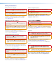
Conventions Used in this Guide Notifications The following notifications are used in this guide: WARNING: A warning indicates a situation that has the potential to result in death or severe injury. ATTENTION: Attention indicates a situation that may damage or destroy the product or associated equipment. NOTE: A note draws attention to important information. Specifications Availability Product specifications are available on the Extron website, www.extron.com.
Contents Introduction............................................................ 1 About this Guide.................................................. 1 Overview............................................................. 1 Features.............................................................. 1 Application Example............................................ 2 Installation............................................................... 3 Installation Considerations...................................
CS 26T and CS 120P User Guide • Contents vi
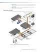
Introduction This section gives an overview of the Extron CS 1226T SpeedMount Ceiling Speaker System, consisting of the CS 26T speakers and CS 120P enclosure. It also provides a list of system features and an application diagram.
• Selectable taps — The rotary tap selector switch, located behind the grille, sets the speaker to operate in either 8-ohm direct or 70 volt /100 volt operation with 16, 8, 4, 2, and 1 watt taps. • Magnetic grille — Magnets spaced around the grille edge enable it to be easily attached and to remain firmly in place. Application Example The illustration below is one example of configuring a system using the CS 1226T.
Installation This section provides instructions for installing the CS 26T speakers and the CS 120P enclosure.
Installing the CS 1226T System — Single Installer If a single installer is installing the CS 1226T system, follow this procedure for the entire system: NOTE: The ceiling grid must be installed before the installation of the CS 1226T begins. • Verify if fiberglass ceiling tiles are being used (see step 2 below and step 11 on page 7 for details).
e. Cut out the circle traced in the ceiling tile. f. Replace the tile in the ceiling. 4. Remove the adjacent ceiling tile — To facilitate the installation process, remove the tile adjacent to the ceiling tile where the CS 26T will be installed. If the CS 120P is being installed, skip to step 6. Otherwise, proceed to step 5. 5.
8. Route the cables through the cover plate — NOTES: • The CS 120P is fully UL 2043 compliant only when it is used with a metal conduit or with plenum rated cables. • Installation of all conduits, conduit adapters, wiring, and electrical connections must conform to all applicable building codes and local ordinances. Using a flexible conduit: a. Route wires through the conduit. b.
9. Wire the CS 120P — Route the wires through the H-shaped opening in the CS 120P. Be sure to leave sufficient slack. Figure 8. Route the Wires Through the H-shaped Opening 10. Replace the terminal cover plate — Reinstall the terminal cover plate onto the CS 120P and tighten the two screws that were previously loosened. 11. If the CS 120P is NOT being installed in a 1-inch (0.25 cm) thick fiberglass ceiling tile, discard the fiberglass tile adapter and proceed to step 12 on the next page.
12. Place the CS 120P into the ceiling grid — Place the CS 120P over the tile grid so that the CS 120P is safely supported on the two short edges. Ensure that the hole in the tile is aligned with the hole in the CS 120P (see figure 10). Fig: Mounting the PRE NOTE: 2' x 2' (600 mm x 600 mm) grid mounting is the same as 2' x 4' (600 mm x 1200 mm) grid mounting. Figure 10. Mounting the CS 120P in a 2" x 2" (600 mm x 600 mm) Ceiling Grid 13.
16. Attach the speaker wires to the captive screw connector — ATTENTION: Do not tin the wires. Tinned wires do not remain tight in the captive screws and can break easily after several bends. Number of Wires per Connection Point Maximum Wire Gauge 1 12 AWG 2 16 AWG 4 18 AWG Attach the speaker wires to the included four-pole captive screw connector using one of the following methods: • Wiring a Single Speaker: Connect the wires to the captive screw connectors of the speakers as shown in figure 12.
• Wiring Multiple Speakers Using Loop-through: A loop-through electrical connection is made on the crossover board of the CS 26T. Connect the wires to the captive screw connectors of the speakers, as shown in figure 15. Be sure to tighten the screws. (Red) (Red) (Black) – –+ + LOOP Power Amplifier (Red) (Black) (Black) IN IN LOOP Speaker 1 – –+ + LOOP IN IN LOOP Speaker 2 Wiring Multiple Speakers Using Loop-through Figure 15.
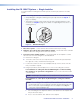
• The impedance of the speakers downstream of the one being tested can be measured while the system is on by connecting to the outer (LOOP) terminals of the captive screw connector, as shown in figure 17. Red Wire (+) from Amplifier Amplifier To next speaker(s) Black Wire (-) from Amplifier Test Points Impedance Points Figure 17. Impedance TestTest Points — Loop-through Configuration 17. Insert the captive screw connector into the four-pole receptacle on the speaker crossover board.
. Attach the speaker wire to the strain relief tie down point using the provided zip tie. Captive Screw Connector Strain Relief Tab (zip tie) Figure 19. Attaching the Speaker Wire to the Strain Relief Point 19. Mount the CS 26T (see figure 20). a. Insert the CS 26T through the bottom of the hole in the ceiling tile that was cut in step 3. b. Tighten the four screws (clockwise) until the speaker is securely clamped to the ceiling. Figure 20.
20. Attach secondary support lines — If required, attach all of the secondary support lines as shown in figure 21. ATTENTION: Do not allow any slack in the support cables. NOTE: If the CS 26T will be installed in the CS 120P, do not attach secondary support cables to the speakers. Anchor ends to suitable solid secure points within the permanent building structure. Secondary Support Cables (3) Secondary Support Cable Attach cables here and secure. Open Back Figure 21.
22. Set the rotary tap selector switch — Use a small screwdriver to set the tap selector switch to the appropriate setting. 100 V 2W 4W 8W 16W Figure 22. 8Ω 8Ω 16W 8W 4W 2W 1W 70 V ATTENTION: When setting the taps for a distributed (high impedance) system, do not tap the system above the rated power of the amplifier. When connecting multiple speakers in 8-ohm mode, be sure that the combined rated impedance does not equal a value less than the minimum rated impedance of the amplifier.
Installing the CS 120P in a Suspended Ceiling — Division of Labor In a division of labor installation, low-voltage contractors install the CS 120P enclosure (construction rough-in phase). NOTE: The ceiling grid must be installed before the installation of the CS 1226T can begin. • Verify if fiberglass ceiling tiles are being used (see step 4d on the next page and step 10 on page 18 for details).
4. Cut a hole for the CS 26T speaker. Use the provided cutout template to outline the hole to be cut in the ceiling tile as described below. (If the ceiling tile will not be installed during this phase of the installation, skip to step 6.) a. Remove the ceiling tile. b. To find the center of the tile, use a tape measure to measure the space between two opposite corners, and mark the half-way point. c.
7. Route the cables through the cover plate — NOTES: • The CS 120P is fully UL 2043 compliant only when it is used with a metal conduit or with plenum rated cables. • Installation of all conduits, conduit adapters, wiring, and electrical connections must conform to all applicable building codes and local ordinances. Using a flexible conduit: a. Route wires through the conduit. b.
8. Wire the CS 120P — Route the wires through the H-shaped opening in the CS 120P. Be sure to leave sufficient slack. Figure 29. Route the Wires Through the H-shaped Opening 9. Replace the terminal cover plate — Reinstall the terminal cover plate onto the CS 120P and tighten the two screws that were previously loosened. 10. If the CS 120P is NOT being installed in a 1-inch (0.25 cm) thick fiberglass ceiling tile, discard the fiberglass tile adapter and proceed to step 11 on the next page.
11. Place the CS 120P into the ceiling grid — Place the CS 120P over the tile grid so that the CS 120P is safely supported on the two short edges. If the ceiling tile was installed, ensure that the hole in the tile is aligned with the hole in the CS 120P (see figure 31). Fig: Mounting the PRE NOTE: 2' x 2' (600 mm x 600 mm) grid mounting is the same as 2' x 4' (600 mm x 1200 mm) grid mounting. Figure 31. Mounting the CS 120P in a 2' x 2' (600 mm x 600 mm) Ceiling Grid 12.
Installing the CS 26T in a Suspended Ceiling — Division of Labor In a division of labor installation, an AV system contractor installs the CS 26T (final installation phase). Use the following procedure: NOTE: Observe all applicable building codes and local ordinances when installing the speaker. 1. Disconnect power — Power down all attached devices before proceeding. 2. (If the ceiling tile is already cut and in place, skip this step.
5. Attach the speaker wires to the captive screw connector — ATTENTION: Do not tin the wires. Tinned wires do not remain tight in the captive screws and can break easily after several bends. Number of Wires per Connection Point Maximum Wire Gauge 1 12 AWG 2 16 AWG 4 18 AWG Attach the speaker wires to the included four-pole captive screw connector using one of the following methods: • Wiring a Single Speaker: Connect the wires to the captive screw connectors of the speaker as shown in figure 33.
• Wiring Multiple Speakers Using Loop-through: A loop-through electrical connection is made on the crossover board of the CS 26T. Connect the wires to the captive screw connectors of the speakers, as shown in figure 36. Be sure to tighten the screws. (Red) (Red) (Black) (Black) – –+ + LOOP Power Amplifier (Red) (Black) IN IN LOOP Speaker 1 – –+ + LOOP IN IN LOOP Speaker 2 Wiring Multiple Speakers Using Loop-through Figure 36.
• The impedance of the speakers downstream of the one being tested can be measured while the system is on by connecting to the outer (LOOP) terminals of the captive screw connector, as shown in figure 38. Red Wire (+) from Amplifier Amplifier To next speaker(s) Black Wire (-) from Amplifier Test Points Impedance Points Figure 38. Impedance TestTest Points — Loop-through Configuration 6. Insert the captive screw connector into the four-pole receptacle on the speaker crossover board.
7. Attach the speaker wire to the strain relief tie down point using the provided zip tie. Captive Screw Connector Strain Relief Tab (zip tie) Figure 40. Attaching the Speaker Wire to the Strain Relief Point 8. Mount the CS 26T (see figure 41). a. Insert the CS 26T through the bottom of the hole in the ceiling tile that was cut in step 2. b. Tighten the four screws (clockwise) until the speaker is securely clamped to the ceiling. Figure 41.
9. Set the rotary tap selector switch — Use a small screwdriver to set the tap selector switch to the appropriate setting. 100 V 2W 4W 8W 16W Figure 42. 8Ω 8Ω 16W 8W 4W 2W 1W 70 V ATTENTION: When setting the taps for a distributed (high impedance) system, do not tap the system above the rated power of the amplifier. When connecting multiple speakers in 8-ohm mode, be sure that the combined rated impedance does not equal a value less than the minimum rated impedance of the amplifier.
Installing the CS 120P in a Hard Ceiling If you are installing the CS 1226T in a hard ceiling (having no ceiling tiles), with the ceiling structure in place, install the CS 120P: • It is the responsibility of the installer to identify a suitable mounting location and provide the mounting hardware. • The CS 120P must be mounted as close as possible to the upper surface of the ceiling material. • The lip of the CS 120P should protrude into the hole cut for the speaker.
Extron Warranty Extron Electronics warrants this product against defects in materials and workmanship for a period of three years from the date of purchase.