User Guide Speakers SF 26X SpeedMount® Ceiling Mount Speakers 68-2222-01 Rev.
Safety Instructions Safety Instructions • English WARNING: This symbol, , when used on the product, is intended to alert the user of the presence of uninsulated dangerous voltage within the product’s enclosure that may present a risk of electric shock. ATTENTION: This symbol, , when used on the product, is intended to alert the user of important operating and maintenance (servicing) instructions in the literature provided with the equipment.
Conventions Used in this Guide Notifications The following notifications are used in this guide: CAUTION: A caution indicates a situation that may result in minor injury. WARNING: A warning indicates a situation that has the potential to result in death or severe injury. ATTENTION: Attention indicates a situation that may damage or destroy the product or associated equipment. NOTE: A note draws attention to important information.
Contents Introduction..................................................... 1 About the SF 26X Speaker ................................. 1 Features.............................................................. 1 Application Example............................................ 2 Installation....................................................... 3 Installing the SF 26X in a Suspended Ceiling....... 3 Painting the Baffle and Grille..............................
Introduction This user guide contains information about the Extron SF 26X Ceiling Mount Speaker. About the SF 26X Speaker The SF 26X speaker is a two-way, low impedance, ceiling-mount speaker system that features an 8 ohm open back speaker with a 6.5 inch woofer and a 3/4 inch tweeter designed for use in non-plenum airspace environments. Features • Open back, infinite baffle design • 8 ohm nominal impedance • 3/4" (1.9 cm) pivoting ferrofluid-cooled dome tweeter • 6.5" (16.
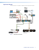
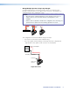
Application Example The illustration below is one example of configuring a system using the SF 26X speakers. Extron TLP 1000TV 10" Tabletop TouchLink Touchpanel Extron DTP HDMI 230 Tx SIG INPUTS POWER 12V 0.
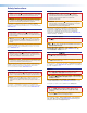
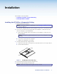
Installation The Installation section describes: • Installing the SF 26X in a Suspended Ceiling • Painting the Baffle and Grille Installing the SF 26X in a Suspended Ceiling 1. Remove power from all devices. NOTE: If the baffle or grille is to be painted, see the Painting the Baffle and Grille section on page 12. The maximum ceiling tile thickness that the speaker can go into is 1.22 inches (31 mm). 2. Cut a hole for the SF 26X.
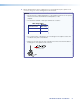
6. Attach speaker wires from the ceiling tile hole to the included four-pole captive screw connector using one of the following three methods below. NOTES: • Be sure that the combined impedance of the speaker system does not equal a value less than the rated minimum load impedance of the amplifier. • The maximum number of wires per terminal are as follows: Wire Gauge Table Number of Wires per Connection Point Maximum Wire Gauge 1 12 AWG 2 16 AWG • Do not tin the wires.
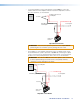
Wiring Multiple Speakers Using Loop-through: A loop-through electrical connection is made on the crossover board of the SF 26X. Connect the wires to the captive screw connectors of the speakers, as shown below. Be sure to tighten the screws. NOTES: • Be sure that the combined impedance of the speaker system does not equal a value less than the rated minimum load impedance of the amplifier.
• To test the impedance of the entire speaker system, first disconnect the speaker wires from the amplifier and then measure the impedance from the disconnected wires, as shown below. Amplifier Red Wire (+) disconnected from Amplifier Test Points To next speaker Black Wire (-) disconnected from Amplifier __ ++ Captive Screw Connector Impedance Test Points ATTENTION: Disconnect the speaker system from the amplifier before performing this test, otherwise you may damage the test meter.
Wiring Speakers in Parallel: Connect the wires to the captive screw connectors of the speakers, as shown below. Be sure to tighten the screws. NOTES: • Be sure that the combined impedance of the speaker system does not equal a value less than the rated minimum load impedance of the amplifier. • When a chain of speakers is wired in this configuration, disconnecting one speaker does not remove power from the remaining speaker in the chain.
To test the impedance of the entire speaker system, first disconnect the speaker wires from the amplifier and then measure the impedance from the disconnected wires, as shown below. Amplifier Red Wire (+) disconnected from Amplifier Test Points To next speaker Black Wire (-) disconnected from Amplifier __ ++ Captive Screw Connector Impedance Test Points ATTENTION: Disconnect the speaker system from the amplifier before performing this test, otherwise you may damage the test meter.
7. Insert the captive screw connector into the four-pole receptacle on the speaker crossover board as shown below. Strain Relief Tie off Point Zip Tie Captive Screw Connector Figure 3. Strain Relief Tie Off Point 8. Secure the speaker wire to the strain relief tie off point using the included zip tie as shown above. 9. Mount the SF 26X. a. Insert the SF 26X through the bottom of the hole in the ceiling tile that was cut in step 2. b.
10. Attach the secondary support line if required, as shown below. Secondary Support Line Figure 5. Secondary Tie off Point Attaching the Secondary Support Line a. Remove the ceiling tile adjacent to the tile where the speaker is mounted. b. Attach the secondary support line. ATTENTION: Do not allow any slack in the secondary support line. c. Replace the adjacent ceiling tile. 11. Pivot the tweeter to aim the mid and high frequencies to the desired spot, as shown below. Figure 6.
12. Position the outer perimeter of the grille into the groove of the speaker baffle. Six magnets pull the grille securely into place, as shown below. Speaker Grille Figure 7. Installing the SF 26X Grille NOTE: Grille hooks are provided for removal of the grille after installation.
Painting the Baffle and Grille NOTE: The cutout template that was used in step 2 of the previous section will be used as a paint shield when painting the outer circumference of the baffle. Painting the Baffle 1. Remove the grille using the provided grille hooks and set the grille aside. 2. Place cutout template over the center of the tweeter so that the woofer and tweeter of the speaker are protected from the paint. 3. Tape over the center hole of the template to prevent any paint from entering the hole.
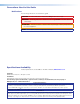
Extron Warranty Extron Electronics warrants this product against defects in materials and workmanship for a period of five years from the date of purchase.