User Guide Graphics Encoders QGE 100 Quantum Graphics Encoder 68-2178-01 Rev.
Safety Instructions • English This symbol is intended to alert the user of important operating and maintenance (servicing) instructions in the literature provided with the equipment. This symbol is intended to alert the user of the presence of uninsulated dangerous voltage within the product’s enclosure that may present a risk of electric shock. Warning Power sources • This equipment should be operated only from the power source indicated on the product.
FCC Class A Notice This equipment has been tested and found to comply with the limits for a Class A digital device, pursuant to part 15 of the FCC Rules. Operation is subject to the following two conditions: 1. This device may not cause harmful interference. 2. This device must accept any interference received, including interference that may cause undesired operation.
Conventions Used in this Guide Notifications In this user guide, the following are used: CAUTION: NOTE: A caution indicates a potential hazard to equipment or data. A note draws attention to important information. TIP: A tip provides a suggestion to make working with the application easier. WARNING: A warning warns of things or actions that might cause injury, death, or other severe consequences.
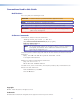
Contents Introduction............................................................ 1 About this Guide................................................. 1 About the QGE 100 Encoder............................... 1 QGE 100 Software........................................... 2 Single or Multiple Users................................... 2 Features............................................................... 3 Functional Overview............................................. 3 Image Capture and Distribution.....
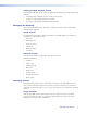
QGE 100 • Contents vi
Introduction This section gives an overview of the Extron QGE 100 Quantum Graphics Encoder, describes its significant features, and provides examples of application diagrams. The following topics are covered: • About this Guide • About the QGE 100 Encoder • Features • Functional Overview • Application Diagrams About this Guide This guide discusses how to install, configure, and operate the QGE 100.
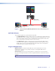
POWER DATA QUANTUM ELITE Quantum Elite Videowall Processor LAN STATUS QGE 100 QUANTUM GRAPHICS ENCODER QGE 100 Network Switch Quantum Graphics Encoder Source PC PC Running Viewer Software Figure 1. Source Computer, QGE 100, Quantum Processor, and Viewing PC on a Network QGE 100 Software Two software programs are provided with the QGE 100: • The QGE 100 Viewer software enables you to select a QGE on the network and view the desktop of a source computer.
Features The QGE 100 features the following: • Allows simple connection of a DVI or RGB source to an IP network. • Streams standard, routable IP packets on an existing network or a dedicated media network. • Lossless compression with 4:4:4, 24-bit color source reproduction maintains image fidelity while minimizing network bandwidth. • Is compatible with DVI input resolutions up to 1920x1200 and analog RGB input resolutions up to 1600x1200.
Viewing the QGE 100 Data Stream Streamed QGE 100 data can be decoded and displayed using any of the following viewing platforms: • A Quantum Elite Videowall Processor (multicast mode only) • A computer running QGE 100 Viewer software • A computer running QGE 100 Administrator software Managing the Network Use the QGE 100 Administrator software to configure the image stream and IP address settings of QGE 100 units.
EDID Management Extended display identification data (EDID) is a communications protocol or instruction set for the identification of a monitor to a source computer that is using the DDC (Display Data Channel) transmission standard. EDID information consists of the native resolution, the vertical interval refresh rate, and pixel clock information about the connected monitor.
Supported Source Formats The table below lists the resolutions and refresh rates supported by the QGE 100.
Application Diagrams Multicast Streaming POWER DATA QUANTUM ELITE Extron Quantum Elite Videowall Processor Projection Cubes Extron QGE 100 Quantum Graphics Encoder PERIPH PC LAN COM 1 12V DC REG 1.5A MAX Refer all servicing to qualified service personnel COM 2 OUT IN DVI-I DVI-I DVI/ RGB DVI/ RGB PC with QGE 100 Viewer software PC with QGE 100 Viewer software Source PC Unicast Streaming with Keyboard and Mouse Control Extron QGE 100 Quantum Graphics Encoder PERIPH PC 12V DC REG 1.
Installation and Operation This section provides the steps to install the QGE 100. It also describes the front and rear panel components and provides instructions for cabling and operating the encoder.
Rear Panel Features 1 2 3 4 5 Reserved for Future Use PERIPH PC COM 1 COM 2 12V DC IN REG 1.5A MAX Refer all servicing to qualified service personnel 9 8 OUT IN DVI-I DVI-I 7 6 Figure 5. QGE 100 Rear Panel a Power connector — Connect the provided 12 VDC power supply to this female 3-pin mini DIN connector (see “Connecting Power to the Unit” for the connection procedure and important cautions).
Connecting the Source Computer to the QGE 100 Video data from the source computer is streamed over the network via the QGE 100 to be viewed on another computer or a Quantum Elite processor. The QGE 100 is compatible with both digital and analog computer graphics signals. NOTE: If you do not intend to use keyboard and mouse control of the source computer through the QGE 100, omit steps 1, 2, 5, and 6 (connecting the QGE between the source computer and its keyboard and mouse).
Analog Connections Digital Connections 1 C2 C1 8 C5 9 17 C3 C4 Analog Portion of DVI Connector 24 Female DVI Connector Pin Signal Pin Signal Pin Signal Pin Function 1 TMDS data 2– 9 TMDS data 1– 17 TMDS data 0– C1 Red signal 2 TMDS data 2+ 10 TMDS data 1+ 18 TMDS data 0+ 3 Ground (2/4 ) 11 Ground (1/3) 19 Ground (0/5) 4 TMDS data 4- 12 TMDS data 3- 20 TMDS data 5- 5 TMDS data 4+ 13 TMDS data 3+ 21 TMDS data 5+ 6 DDC clock 14 +5 V power* 22 Ground (clock) 7 DDC
2. Plug the DVI-A connector of the adapter into the QGE DVI-I Out port. Analog to DVI Adapter Analog Monitor To QGE 100 DVI I Out Port Figure 8. Connecting the Monitor of an Analog Source Computer to the Analog to DVI Adapter NOTE: If you use a monitor cable or adapter other than the one provided with the QGE 100, ensure that all pins are properly interconnected; otherwise, the computer graphics card or monitor may not operate correctly.
2. When the QGE 100 encoder is delivered, the following default addresses are set for it: • IP address: 172.28.231.98 • Subnet mask: 255.255.000.000 If you need to change these addresses, use the QGE 100 Administrator software to enter new addresses (see the “Software Configuration and Control” section for detailed procedures). The IP address must be within the range of addresses that have been specified for your network and cannot be in use by another network device.
CAUTIONS: • Do not permanently fix the power supply to the building structure or similar structures. • Do not place the power supply within environmental air handling spaces or the wall cavity. • The installation must be in accordance with the applicable provisions of the National Electrical Code ANSI/NFPA 70, Article 725 and the Canadian Electrical Code, Part 1, Section 16.
Connections with a Digital Source Source Computer Mouse PS/2 to PS/2 Network PERIPH QGE 100 Quantum Graphics Encoder Keyboard PC 12V DC IN REG 1.5A MAX Refer all servicing to qualified service personnel DVI Monitor Out DVI-D to DVI-D IMPORTANT: Fit the clip-on ferrite to this end of the cable. COM 1 COM 2 OUT IN DVI-I DVI-I Power Supply DVI Monitor Figure 10.
Connections with an Analog Source Source Computer Mouse Keyboard PS/2 to PS/2 Network PERIPH QGE 100 Quantum Graphics Encoder PC 12V DC IN REG 1.5A MAX Refer all servicing to qualified service personnel Analog Monitor Out 15-pin HD to DVI-A IMPORTANT: Fit the clip-on ferrite to this end of the cable. COM 1 COM 2 OUT IN DVI-I DVI-I DVI-A to 15-pin HD Adapter Power Supply Analog Monitor Figure 11.
Front Panel Features 1 2 LAN STATUS QGE 100 QUANTUM GRAPHICS ENCODER 3 Figure 12. QGE 100 Front Panel The QGE 100 front panel contains three indicator LEDs: a Power LED — This green LED lights steadily when the unit is receiving power from the power supply. b LAN LED — This orange led indicates the status of the Ethernet connection: c • Blinking irregularly: Data is being transmitted across the network. • Unlit: No data is being transmitted from the source, or no source is connected.
Software Configuration and Control This section describes the QGE 100 software programs and provides procedures for using them to configure and operate the QGE.
Installing the Software The Administrator software and Viewer software programs for the QGE 100 are provided on a CD with the unit (they are not available for downloading from the web). Install each program on your computer as follows: 1. Insert the Extron Videowall Processing CD into the disk drive of your PC and wait for your CD drive root directory screen to open. If the CD does not start automatically, open your Windows Explorer and click on the external drive name to display the CD root directory. 2.
2. In the QGE 100 List section, select one of the listed QGEs by clicking on its name to highlight it. 3. Click the Connect button in the Tasks section. The current information on your selected QGE is displayed in the QGE 100 List section; and the Viewer window opens, displaying the current screen of the connected source device (see “The Administrator Viewer window” on page 24 for a description of this window).
QGE 100 List section The QGE 100 List section displays information on all QGEs detected by the Administrator software at startup. The figure below shows an example of a QGE 100 List section in which two QGEs are displayed: one connected in multicast mode and one in unicast mode. QGEs that appear grayed-out on this list are not connected; they are showing details from the last time they were connected. Click Refresh to update the connection. Figure 14.
Configure QGE 100 Properties section The QGE 100 Properties section provides fields in which you can select or enter parameters for the QGE, such as the IP address, frame rate, and so forth. You must log in as administrator in order to be able to access the fields in this section (see “Logging In and Out (Administrator Level)” on page 28).
Tools menu Option Description Mouse and Keyboard Options Opens a window that lets you set some parameters for keyboard and mouse control of the source PC. Options Opens a window that lets you specify whether explanatory messages appear when you initiate certain actions. Logging Opens a window that lets you enable or disable multicast error logging and set an interval at which to check for errors. Admin menu Option Description Log in Opens a dialog on which to enter the administrator password.
Viewing a QGE 100 Source The QGE 100 Administrator provides a Viewer window on which you can view a connected source. You can also view sources using the QGE 100 Viewer software (see “Using the QGE 100 Viewer Program” on page 34). You can display the source that is connected to any QGE 100 in the list as follows: 1. Select a QGE in the list that you want to view. 2. Connect the Administrator software to the selected QGE by any of the following methods: • Click the Connect button in the Task section.
The Administrator Viewer window contains a menu bar and a toolbar from which you can specify parameters for viewing the displayed source. The table below describes these controls. Administrator Viewer menu Options Menu Option Toolbar Icon Description Connection menu Disconnect Disconnects the Administrator software from the QGE stream and closes the Viewer window. View menu Scale Places the Viewer window in scale mode. In this mode, the source image fills the display portion of the window.
Managing the QGE 100 List You can perform the following tasks on the QGE 100 List: Refreshing the list After being closed and reopened or after list items have been added or removed, the Administrator software does not automatically update the QGE 100 List. After making changes to any of the items in the QGE 100 List or Configure QGE 100 Properties section, do any of the following to display the latest information: • Click the Refresh button in the Tasks section.
2. Enter the requested information in the text fields, then click OK. Figure 16. Add QGE 100 Window Deleting a QGE from the list You can remove QGEs from the QGE 100 List individually or in groups. To delete a device: 1. In the QGE 100 List, select the QGE that you want to delete. To select multiple devices, hold down the or key while clicking on the QGE names. 2. From the Connection menu, select Delete. 3. Save the list (see “Saving the list” on page 26).
Logging In and Out (Administrator Level) By default, you are logged in at user level when you first open the Administrator software (your current login level is shown on the status bar at the bottom of the QGE 100 window). All fields in the Configure QGE 100 Properties section are grayed-out. Figure 17. Status Bar on the Main Application Window in User Mode To make changes to any QGE 100 settings, you must log in at administrator level as follows: 1. From the Admin menu, select Log in.
Configuring a QGE 100 The Configure QGE 100 Properties section of the main window contains fields in which you can specify or change various properties of a selected QGE 100. NOTE: You must be logged in as Administrator in order to edit these sections (see “Logging In and Out (Administrator Level)” on the previous page). Figure 20. Configure QGE 100 Properties Section of the Administrator Window To change any of the settings described in the following sections, follow this general procedure: 1.
Figure 22 Figure 22. Network Settings Window The table below lists and describes the network settings that can be changed. Setting Description IP Address Enter the IP address for the QGE 100 (see “IP Addressing” in the “Reference Information” section for basic information about IP addresses). The factory default IP address is 172.28.231.98. Subnet Mask Enter the subnet IP address. The default subnet mask is 255.255.0.0 (see “Subnetting, a Primer” in the “Reference Information” section).
Configuring UDP multicast settings To use a Quantum Elite processor as a viewing device or to connect the QGE 100 source to multiple viewing devices, you must place the QGE in multicast mode. You can configure multicast connection parameters by making changes to the fields in the Network Settings section of the QGE 100 main window. Figure 23. Network Settings Section for UDP Multicast Configuration To change multicast settings: 1.
Configuring the QGE for Use with a Quantum Elite Processor To use a Quantum Elite Videowall Processor as a viewing device, use the Quantum Elite Control Software, provided on the Extron Videowall Processing CD. (See the Quantum Elite and Quantum Connect User Guide for details on accessing and loading this software). 1. Ensure that the QGE is in multicast mode (see “Configuring UDP multicast settings” on page 31). 2.
Example: Figure 25. Set Up Sources Screen on the Quantum Control Software Main Window For detailed information on setting up sources, see the Quantum Control Software User Guide, available on the Extron website at www.extron.com.
Using the QGE 100 Viewer Program The QGE 100 Viewer software displays QGE 100 sources on your viewing computer. It can display one source at a time. Starting the Viewer Program For you to start using the QGE 100 Viewer software, the RJ-45 LAN connector on the QGE 100 rear panel must be connected to a switch or router that is connected to the same network as your viewing device or computer. (The viewing device can be connected to the same switch or router as the QGE 100 if desired.
The QGE 100 Viewer Window Figure 26. QGE 100 Viewer Main Window The main window of the QGE 100 Viewer consists of the following major sections: • Source window — (Left pane) Displays the source connected to the selected QGE 100. If no source is connected, this section displays Not Connected. • Channel list — (Right pane) Displays all QGE 100s available on the network.
Menus and toolbar The QGE 100 Viewer window contains a menu bar and a toolbar from which you can specify parameters for viewing the displayed source. The following tables describe the options available on the menus and any equivalent toolbar buttons. Connection menu Option Toolbar Icon Description Connect Connects the QGE 100 Viewer software to the QGE. Clicking the down arrow to the right of the icon displays a list of the most recently connected QGEs, from which you can select a source as well.
View menu Option Toolbar Icon Description Refresh Channel List Updates the information in the Channel (QGE 100) list in the right pane of the Viewer main window. Scale Places the Viewer source pane in scale mode. In this mode, the source image fills the source (left) pane. To increase or decrease the size of the image, drag the edges or corners of the source pane. NOTE: The scaled image may take several seconds to display. To exit scale mode, click or select Unity.
Tools menu Option Description Mouse & Keyboard Toggles mouse and keyboard control on and off (see “Mouse and Keyboard Control of the Source Computer” on page 41). Mouse and Keyboard Options Opens a window that lets you set some parameters for keyboard and mouse control of the source PC. Options Opens a window that lets you specify whether explanatory messages (learning dialogs) appear when you initiate certain actions.
Connecting using the Connect dialog box To connect to a QGE by entering its name or IP address in the Connect dialog box: 1. From the Connection menu, select Connect To. The Connect dialog box opens. 2. Click in the text field and enter the name or IP address of the QGE to which you want to connect; or Select a QGE from the drop-down menu of recently connected sources. Figure 27. Connect Dialog Box with Recent Connections Menu Displayed 3. Click OK. The dialog box closes.
Learning Dialogs Learning dialogs are pop-up windows that the Administrator and QGE 100 Viewer programs display when you perform certain operations. These dialogs provide additional information that may be helpful while you are learning to use the software (to close a learning dialog, click its OK button). You can disable or enable them as you need them. The following figure shows an example of a learning dialog, which appears when you select full screen viewing mode. Figure 28.
Mouse and Keyboard Control of the Source Computer The keyboard and mouse of the computer that is running QGE 100 Administrator or QGE 100 Viewer can be set up to control (emulate mouse and keyboard operation of) the source computer through the QGE 100. This is available only when the QGE is in unicast mode. (QGEs in multicast mode cannot be set up for remote control because they can have more than one viewing device connected.
2. Enter any desired values in the fields as described in the table below: Field To enter a value: Key Combination to End Mouse & Keyboard Input Click in this field, then press the key or key combination that will be used to terminate the current mouse and keyboard control session. Default: + NOTE: Pressing this key combination does not disable keyboard and mouse control entirely.
Starting and stopping a mouse and keyboard control session • To start a session in which your viewing computer controls the keyboard and mouse of the source computer, click anywhere on the Viewer window of the Administrator program or the source pane of the QGE 100 Viewer main window. A red border appears around the source display area. Figure 31.
Using the Special Context menu The Special Context pop-up menu contains commands that you can select to send to the source computer during a mouse and keyboard control session. (You can display this menu only during a control session.) Figure 32. Special Context Pop-up Menu To use the Special Context menu: 1. Press the key combination specified on the Mouse & Keyboard Options window (by default, this is + ). The Special Context menu pops up and a mouse pointer appears on the Viewer window. 2.
Reference Information This section contains reference information about the QGE 100.
Ethernet data rate �������������������������� 10/100Base-T, half duplex with autodetect Ethernet protocol ��������������������������� IP, TCP, UDP, DHCP Ethernet default settings ���������������� Link speed and duplex level = autodetected IP address = 172.28.231.98 Subnet mask = 255.255.0.0 Gateway = 0.0.0.
Part Numbers and Accessories The following tables list the items that are shipped with the QGE 100, or can be ordered for use with it. If you need replacement parts, contact your Extron representative for assistance (see the last page of this guide for contact information). Included Parts These items are included with each order for a QGE 100.
Mounting the QGE 100 Encoder The QGE 100 encoder can be placed on a tabletop or mounted in a rack. NOTE: Always use the special QGE 100 rack mounting kit (part number 70-755-01), available separately, to secure the unit to the rack. Mounting instructions are included with the kit.
IP Addressing What is an IP Address? A full explanation of IP addressing is beyond the scope of this user guide. However, the following details provide enough information to get started. An IP address is a 32-bit binary number that is used to identify each device on an Ethernet network. This number is usually represented by four decimal numbers (each in the range or 0 to 255) separated by dots, such as 198.123.34.240. This is called “dotted decimal notation.
The following is an example of an invalid Class C addressing scheme: Device IP Address QGE 100 viewing computer 208.132.180.41 QGE 100 encoder 1 192.157.180.42 QGE 100 encoder 2 209.100.123.43 NOTE: The above addresses are invalid because the network identifier for each address is not the same even though each IP address is unique.
4. At the command prompt, enter ping IP address. The computer returns a display similar to the figure below. The Pinging ... line reports the actual numeric IP address, regardless of whether you entered the address or an alias name. Figure 34. Ping Response Pinging to determine the web IP address The Ping utility has a modifier, -a, that directs the command to return the web address rather than the numeric IP address. At the prompt, enter ping -a IP address.
IP addresses and octets Valid IP addresses consist of four 1-, 2-, or 3-digit numeric sub-fields, called “octets,” which are separated by dots (periods) (figure 35, below). Each octet can be numbered from 000 through 255. Leading zeros, up to 3 digits total per octet, are optional. Values of 256 and above are invalid. Typical IP Address: 192.168.254.254 Octets Figure 35.
Troubleshooting Performance In an ideal QGE 100 system, the source displayed on the viewing device should be virtually indistinguishable from the original source. However, under certain circumstances, you may notice some reduction in performance. This section describes the problems you may encounter and provides suggestions for minimizing or avoiding them. Performance Criteria The performance criteria include the following: • Image Refresh Rate — how often the display content is updated.
TIP: In addition to the improved image quality that digital sources provide, they are also more efficient on encoding. This is because analog sources invariably contain a certain amount of noise and this can add to the overall content of the data stream. In addition, analog sources may produce contouring effects during motion. • Network Bandwidth — This is the total volume of data that can be handled by the network at any given time.
Optimizing the Encoder Parameters Using the QGE 100 Administrator software, you can set the parameters listed below (see “Using the QGE 100 Administrator Program” in the “Software Configuration and Control” section): • Bandwidth Limit — If you are using a large number of QGE 100s or you have a slow or busy network, you can reduce this value, which sets the maximum possible flow of data being streamed onto the network.
Extron Warranty Extron Electronics warrants this product against defects in materials and workmanship for a period of three years from the date of purchase.