User Guide XTP Power Injector XTP PI 400 Four Port XTP Power Injector 68-2291-01 Rev.
Safety Instructions Safety Instructions • English WARNING: This symbol, , when used on the product, is intended to alert the user of the presence of uninsulated dangerous voltage within the product’s enclosure that may present a risk of electric shock. ATTENTION: This symbol, , when used on the product, is intended to alert the user of important operating and maintenance (servicing) instructions in the literature provided with the equipment.
FCC Class A Notice This equipment has been tested and found to comply with the limits for a Class A digital device, pursuant to part 15 of the FCC rules. The Class A limits provide reasonable protection against harmful interference when the equipment is operated in a commercial environment. This equipment generates, uses, and can radiate radio frequency energy and, if not installed and used in accordance with the instruction manual, may cause harmful interference to radio communications.
Conventions Used in this Guide Notifications The following notifications are used in this guide: WARNING: A warning indicates a situation that has the potential to result in death or severe injury. ATTENTION: Attention indicates a situation that may damage or destroy the product or associated equipment. NOTE: A note draws attention to important information. Specifications Availability Product specifications are available on the Extron website, www.extron.com.
Contents Introduction.................................................... 1 About the XTP PI 400.......................................... 1 Features.............................................................. 2 Installation and Operation............................ 3 Installation........................................................... 3 Important Safety Instructions........................... 3 Rear Panel Connectors.................................... 5 Installation Overview.........................
XTP PI 400 Power Injector • Contents vi
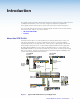
Introduction This guide contains information about the Extron XTP PI 400 Power Injector with instructions for experienced installers on how to install, configure, and operate the equipment. In this guide, the term “XTP PI 400” is used to refer to the XTP PI 400 Power Injector. This section provides basic information about this guide, the XTP PI 400, and key features of the XTP PI 400.
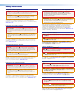
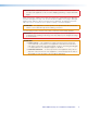
1.0A MAX. 12V POWER Tx Rx RS-232 SIG LINK RESET POWER 12V --A MAX Figure 2. INPUTS 1 2 3 100-240V SIG XTP OUT XTP PI 400 XTP Power Injector 50/60 Hz AUDIO ACT LAN LINK RS-232 Tx Rx IR Tx Rx XTP 1 2 LINK OVER XTP CONTACT 3 XTP PWR XTP 1 PWR XTP PWR XTP T USW 103 XTP Transmitter 2 XTP PWR XTP PWR PWR PWR SIG SIG SIG LINK LINK LINK x.
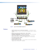
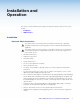
Installation and Operation This section contains installation procedures and operation features. Topics in this section include: • Installation • LED Indicators Installation Important Safety Instructions This symbol, when used on the product, is intended to alert the user of important operating and maintenance (servicing) instructions in the literature provided with the equipment.
WARNING: Risk of electrical shock. To reduce the risk of fire or electric shock, do not expose this apparatus to rain, moisture, dripping, splashing, or objects filled with liquids. Refer all servicing to qualified service personnel.
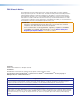
Rear Panel Connectors b 100-240V c b c b c b c 1.6 A XTP PI 400 1 2 3 PWR XTP 50/60 Hz Figure 3. 4 PWR XTP PWR XTP PWR XTP PWR XTP PWR XTP PWR XTP XTP PWR Rear Panel Features Do not connect these devices to a computer data or telecommunications ATTENTION: network. NOTE: The XTP PI 400 does not switch XTP signals. a b c AC power connector — Connect the IEC power cord to the AC power connector.
Twisted Pair Cable Recommendations Use the following pin configurations for twisted pair cables. Pins: 12345678 TIA/EIA-T568B Pin Wire Color 1 Pin T568A Wire color T568B Wire color White-orange 1 White-green White-orange 2 Orange 2 Green Orange 3 White-green 3 White-orange White-green 4 Blue Blue 4 Blue 5 White-blue White-blue 5 White-blue 6 Orange Green 6 Green 7 White-brown 8 Brown Figure 6.
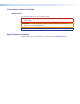
LED Indicators a b 1 XTP POWER OUT 2 3 4 XTP PI 400 XTP POWER INJECTOR Figure 7. Front Panel Features a Front panel power LED indicator — Lights to indicate the XTP PI 400 is receiving power. b Front panel XTP Power Out LED indicators — Light when the XTP PI 400 is providing power to XTP devices connected to the XTP PWR connectors.
Reference Information Mounting The XTP PI 400 is 1U high and one half rack wide. ATTENTION: • The XTP PI 400 is not suitable for use in air handling spaces or in wall cavities. The power supply must be located within the vicinity of the Extron AV equipment in an ordinary location with pollution degree 2, and secured to an equipment rack within a dedicated closet, podium, or desk.
Rack Mounting Rack inch Box Standard Shelf Mount the Half XTP PI 4009.5 to an optional Extron rack shelf. To mount the unit on a rack shelf, follow the instructions provided with the shelf accessories. 1U Universal Rack Shelf 1/2 Rack Width Front False Faceplate Front false faceplate uses 2 screws. (2) 4-40 x 3/16" Screws NOTE: Using screws longer Use 2 mounting holes on opposite corners. Figure 8. than 3/16" will damage the unit and void the warranty.
Extron Warranty Extron Electronics warrants this product against defects in materials and workmanship for a period of three years from the date of purchase.