User Guide Signal Processors DVC 501 SD SDI Converter 68-1518-01 Rev.
Safety Instructions • English This symbol is intended to alert the user of important operating and maintenance (servicing) instructions in the literature provided with the equipment. This symbol is intended to alert the user of the presence of uninsulated dangerous voltage within the product enclosure that may present a risk of electric shock. Warning Power sources • This equipment should be operated only from the power source indicated on the product.
FCC Class A Notice This equipment has been tested and found to comply with the limits for a Class A digital device, pursuant to part 15 of the FCC Rules. Operation is subject to the following two conditions: 1. This device may not cause harmful interference. 2. This device must accept any interference received, including interference that may cause undesired operation.
Conventions Used in this Guide In this user guide, the following conventions are used: NOTE: A note draws attention to important information. TIP: A tip provides a suggestion to make working with the device easier. CAUTION: WARNING: A caution indicates a potential hazard to equipment or data. A warning warns of things or actions that might cause injury, death, or other severe consequences.
Contents Introduction............................................................ 1 Remote Configuration and Control................. 21 About this Guide................................................. 1 About the DVC 501 SD Converter....................... 1 Features............................................................... 1 Application Diagram............................................ 2 Communication Ports........................................ 21 Using SIS Commands..........................
DVC 501 SD • Contents vi
Introduction This section gives an overview of the Extron DVC 501 SD Digital Video Converter. Topics include: • About this Guide • About the DVC 501 SD Converter • Features • Application Diagram About this Guide This guide provides information for experienced installers on how to install, configure, and operate the DVC 501 SD converter. In this guide, the terms “DVC,” “DVC 501 SD,” and “converter” are used interchangeably to refer to the DVC 501 SD converter.
• Analog RGB or component video output — Outputs analog RGB as RGBHV, RGBS, or RGsB. Outputs component video as R-Y, B-Y, Y. • Buffered loop-through connector — A buffered input loop-through delivers reshaped and restored multi-rate SDI signals. • Bi-level or tri-level sync is available for component video output. • Internal test patterns for calibration and setup — Nine test patterns are available, including a crop pattern, color bars, and grayscale.
Installation This section gives an overview of the steps for installing the DVC 501 SD. It also provides a description of the rear panel connectors and instructions for cabling. Topics include: • Installation Overview • Rear Panel • Connecting for Remote Control Installation Overview CAUTION: Installation and service must be performed by authorized personnel only. Follow these steps to install and set up the DVC 501 SD: 1.
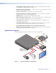
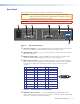
Rear Panel The illustration below shows the connectors on the DVC 501 SD rear panel. CAUTION: Use electrostatic discharge precautions (be electrically grounded) when making connections. Electrostatic discharge (ESD) can damage equipment, although you may not feel, see, or hear it. WARNING: Remove power from the system before making any connections. 2 1 100-240V ~ 0.
f Audio output connector — Connect an audio device to this female 5-pole 3.5 mm captive screw connector for balanced or unbalanced analog audio output. Wire the connector as shown below. Figure 4. R R Balanced Audio Output Tip Sleeves Tip L L Tip Ring Sleeves Tip Ring Do not tin the wires! Unbalanced Audio Output Audio Output Connector Wiring CAUTIONS: • The length of the exposed wires in the stripping process is critical. The ideal length is 3/16 inches (5 mm).
RS-232 DVC 501 SD or Rear Panel RS-232 Port N/A Tx Rx 1 2 3 NOTE: Connect a ground wire between the DVC and the computer or control system. Ground ( ) Receive (Rx) Transmit (Tx) Transmit (Tx) Receive (Rx) NOTE: If you use cable that has a drain wire, tie the drain wire to ground at both ends. Figure 5. Computer or Control System RS-232 Port Connecting to the RS-232 Port In the “Remote Configuration and Control” section, see “Using SIS Commands” for information on sending SIS commands to this port.
2. If this is the first time you have connected a DVC 501 SD to this particular USB port on your computer, the Found New Hardware Wizard opens. On the first screen, specify whether you want the computer to connect to Windows® Update in order to search the web for the driver that it needs to communicate with the DVC via the USB port (this is not necessary if the USB driver already exists on your computer). Figure 7.
3. Click Next. On the next screen, make sure that the Install the software automatically (Recommended) radio button is selected, then click Next (you do not need to insert a disc). Figure 8. Selecting the Radio Button to Install the USB Driver Automatically Your computer locates the driver needed for it to communicate with the DVC 501 SD via the USB port. 4. When the Completed screen appears, click Finish to close the wizard.
Operation This section discusses the functions available through the front panel to set up and operate the DVC 501 SD. Topics include: • Front Panel • Powering On • Menus on the LCD Screen • Resetting • Front Panel Lockout (Executive Mode) • Updating Firmware Front Panel 1 2 3 MENU 4 5 ADJUST NEXT CONFIG DVC 501 SD DIGITAL VIDEO CONVERTER Figure 9. DVC 501 SD Front Panel The front panel features and controls shown in the illustration above are described starting below.
Powering On Apply power by connecting the provided IEC power cord to the rear panel power connector on the DVC. Connect the DVC to an AC power source. NOTE: Audio and video mute settings are not retained when power is cycled to the DVC. Default Cycle When power is applied, the LCD screen displays the Extron S3 logo. After approximately 10 seconds, EXTRON DVC 501 SD is displayed. The unit part number and current firmware version are displayed after approximately another 5 seconds.
• Overheating — The Temperature Overload!!! screen is added to the default cycle if the internal temperature of the unit exceeds 65 °C (149 °F). INPUT HDSDI 1.485G 5 sec. INPUT 720p @59.94Hz 5 sec. TEMPERATURE OVERLOAD!!! 5 sec. Figure 12. Example of the Default Cycle When the Unit Is Overheating • Video muted — The input resolution and rate screen (second screen of the default cycle) displays a blinking asterisk (*) on both sides of the word INPUT.
NOTE: The menus time out and the default cycle is displayed after 30 seconds of inactivity; however, any selections you made with the Adjust knobs are saved and remain in effect until you change them or reset the unit to factory defaults (see “Resetting,” later in this section). Menu flow diagram The flow diagram below shows the menus that are displayed in the front panel LCD screen and the order in which they appear when you repeatedly press the Menu button. Default Cycle Menu OUTPUT CONFIG 30 sec.
Output Configuration Menu The output configuration menu allows you to set the output resolution and refresh rate, the output signal type, and the sync polarity (RGBHV only). The following flow diagram shows the output configuration submenus and the adjustments that can be made from them. Default Cycle *This screen appears only if RGBHV is selected for the format. Menu OUTPUT CONFIG FORMAT RGBHV Next H POS Next SYNC V POS Use either Adjust knob to select a submenu option.
Audio Config Menu The Audio Config menu enables you to adjust the level of attenuation, mute and unmute the audio, and select the pair of audio channels on which to extract the audio from the 3G-SDI, HD-SDI, or SD-SDI signal. The flow diagram below shows the audio configuration submenus and the adjustments that can be made from them. OUTPUT CONFIG Menu AUDIO CONFIG AUDIO MUTE DISABLED Next Next GAIN/ATTEN 0 dB Turn either Adjust knob to select a setting. Mute or unmute the audio.
Advanced Config Menu The Advanced Config menu enables you to select a test pattern and to view the internal temperature of the unit. The flow diagram below shows the advanced configuration menu and submenus and the adjustments that can be made from them. AUDIO CONFIG Menu ADVANCED CONFIG TEST PATTERN OFF Next Next INT. TEMP 91F 33C Use either Adjust knob to select a submenu option. Select a test pattern: • OFF (default) • • COLOR BARS • • GRAYSCALE • • X-HATCH 4x4 • • ALT. PIXELS • Figure 18.
Color Bars Crop Grayscale 1.33 Aspect X-Hatch 4x4 1.78 Aspect Alt Pixels 1.85 Aspect 2.35 Aspect Figure 19. DVC 501 SD Test Patterns Int. Temp. screen The Int. Temp. screen shows the current internal temperature of the DVC unit in degrees Fahrenheit and Celsius. This is an information-only screen; no adjustments can be made from it. Exiting the Menu System To exit the menu system, press the Menu button repeatedly until the EXIT MENU PRESS NEXT screen appears.
Front Panel Lockout (Executive Mode) To prevent accidental changes to settings, you can lock the DVC 501 SD front panel controls by placing the converter in lock (executive) mode. While the DVC is in lock mode, RS-232 communication remains available, as well as the ability to exit lock mode. • To enable lock mode, press and hold the Menu and Next buttons simultaneously until EXE MODE ENABLED appears in the LCD window (approximately 2 seconds).
4. On the Add Device window, select DVC 501 SD from the Device Name drop-down menu. Figure 20. Device Name Drop-down Menu on the Add Device Window 5. From the Connection Method drop-down menu, select RS-232 or USB. 6. If using RS-232, select the appropriate options from the Com Port and Baud Rate menus (this information is provided by your system administrator). 7. Click Connect. If the connection is successful, DVC 501 SD is displayed in green and followed by a check mark in the Connected Device section.
NOTES: • The original factory-installed firmware is permanently available on the DVC 501 SD. If the attempted firmware upload fails for any reason, the converter reverts to the factory-installed firmware. • When downloaded from the Extron website, by default the firmware is placed in a folder at C:\Program Files\Extron\Firmware\DVC 501 SD or C:\Program Files (x86)\Extron\Firmware\DVC 501 SD (for Windows 7). 10. On the Add Device window, the path to the new firmware file is displayed in the Path field. 11.
12. Click Begin. The following indicators on the Firmware Loader window show the progress of the update: • The Transfer Time section shows the amount of remaining and elapsed time for the update. • The Total Progress section displays a status bar with Uploading... above it. • In the Devices section, the Progress column displays an incrementing percentage and the Status column displays Uploading. The LCD screen on the DVC front panel displays FW. UPLOAD PLEASE WAIT. Figure 23.
Remote Configuration and Control This section describes the connections through which the DVC 501 SD can be configured and controlled remotely via SIS commands, and describes the commands that are available. Topics include: • Communication Ports • Using SIS Commands • Command and Response Table Communication Ports The DVC 501 SD can be remotely controlled via a host computer or other device (such as a control system) that is connected to the rear panel RS-232 port or the front panel USB Config port.
Error Responses When the DVC receives a valid command, it executes the command and sends a response to the host device. If the unit is unable to execute the command because the command contains invalid parameters, it returns an error response to the host.
Symbol Definitions • = ] = } = E = | = W = Space Carriage return with line feed Carriage return with no line feed Escape Pipe (vertical bar) character. Has the same function as ]. Has the same function as E.
Command and Response Table ASCII Command Response (Host to Converter) (Converter to Host) Mute video 1B Vmt1 ] Mute (blank) the video output. Unmute video 0B Vmt0 ] Display the output. View mute status B X! ] Show video mute status X!. For X!: 0 = mute off, 1 = mute on. Command Additional Description Video Mute Output Configuration Output Sync Polarity Set polarity E X% OPOL } Opol X% ] Set the sync polarity for the VGA output to X%.
Command ASCII Command Response (Host to Converter) (Converter to Host) Additional Description Advanced Configuration Test pattern Select a test pattern E X$ TEST } Test X$ ] Select test pattern X$. For X$: 0 = Off (default) 1 = Color Bars 2 = Grayscale 3 = 4x4 Crosshatch 4 = Alternating Pixels 5 = Crop 6 = 1.33 Aspect Ratio Crop 7 = 1.78 Aspect Ratio Crop 8 = 1.85 Aspect Ratio Crop 9 = 2.35 Aspect Ratio Crop Turn off test patterns E 0TEST } Test0 ] Disable the test pattern.
Reference Information This section provides reference information on the DVC 501 SD. The following topics are covered: • Specifications • Part Numbers and Accessories • Mounting the DVC 501 SD Converter Specifications Video Signal type ������������������������������������� Data rates �������������������������������������� Operation standards ����������������������� Auto data rate lock ������������������������ SDI, HD-SDI, and 3G-SDI digital video signals 270 Mbps, 1.485 Gbps, 2.
Video output Number/signal type ������������������������ 1 single link DVI-D 1 RGB, YUV / YPbPr Connectors ������������������������������������ 1 female DVI-I 1 female 15-pin HD Nominal level TMDS �������������������������������������� 1.0 Vp-p swing Analog ������������������������������������ 1 Vp-p for Y of component video 0.
General Power supply ���������������������������������� Internal Input: 100 VAC to 240 VAC, 50-60 Hz Power consumption ����������������������� 12 watts Temperature/humidity �������������������� Storage: -40 to +158 °F (-40 to +70 °C) / 10% to 90%, noncondensing Operating: +32 to +122 °F (0 to +50 °C) / 10% to 90%, noncondensing Cooling ������������������������������������������ Convection, sides to top Thermal dissipation ������������������������ 24 BTU/hr Mounting Rack mount ����������������������������� Y
Part Numbers and Accessories Included Parts Description Part Number DVC 501 SD 60-1033-01 Rubber feet (not attached) (4) IEC power cord (1) 5-pole captive screw connectors (2) DVC 501 SD Setup Guide Optional Accessories These items can be ordered separately: Description Part Number RSU Universal Rack Shelf Kit 60-190-01 RSB Basic Rack Shelf 60-604-02 MBU 125 Under-desk Mounting Kit 70-077-01 MBD 129 Through-desk Mounting Kit 70-077-02 UC50' Universal Projector Control cable, 50' (15.
Rack mounting procedure To rack mount the converter, you can use one of the Extron 19 inch rack shelf mounting options (see “Optional Accessories,” earlier in this section, for part numbers). Half-rack false front panel uses 2 front holes. DIG ITA L DV C VID EO (2) 4-40 x 3/16" screws Use 2 mounting holes on opposite corners. 50 CO 1S NVE D RTE R Figure 27. Rack Mounting the DVC 501 SD 1. If rubber feet have been installed on the bottom of the unit, remove them. 2.
Through-desk Mounting Mount the converter through a desk or table, using the optional MBD 129 through-desk mounting kit (see “Optional Accessories” for the part number). 1. If rubber feet are attached to the bottom of the unit, remove them. 2. Loosely attach the mounting brackets to the unit using the four machine screws and washers supplied with the mounting kit. Figure 28. Through-desk Mounting the DVC 501 SD 3. Hold the DVC against the inside of the surface through which it will be mounted.
Extron® Warranty Extron Electronics warrants this product against defects in materials and workmanship for a period of three years from the date of purchase.