USP 405 Universal Signal Processor 68-541-01 Rev.
Precautions Safety Instructions • English This symbol is intended to alert the user of important operating and maintenance (servicing) instructions in the literature provided with the equipment. This symbol is intended to alert the user of the presence of uninsulated dangerous voltage within the product's enclosure that may present a risk of electric shock. Warning Power sources • This equipment should be operated only from the power source indicated on the product.
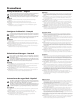
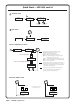
Quick Start — USP 405 Installation RGB or component video output Step 1 RGB or HD component video output Turn off power to the USP 405 and the input and output devices, and remove the power cords. RGBHV Step 2 RGB/R-Y, B-Y, Y RGBS R /R-Y G /Y B /B-Y R /R-Y G /Y B /B-Y H V S H V S R /R-Y G /Y B /B-Y R /R-Y G /Y B /B-Y H V S H V S Install the four rubber feet on the bottom of the USP 405, or mount the USP in a rack. Step 3 Attach input devices to the USP.
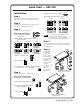
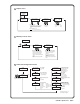
Quick Start — USP 405, cont’d USP 405 Menu System Default Cycle menu Default Cycle Extron USP 405 SDI I Extron USP 405 SDI O Power on 60-369-0x Version x.xx 2 sec. Input #1 RGBHV 2 sec. Horz. 00.00 KHz Vert. 00.00 Hz 2 sec. Output Rate 1024 x 768 @ 60 2 sec. 2 sec. Extron USP 405 SDI IO Main menu Power on 60-369-0x Version x.xx 2 sec. Extron USP 405 2 sec. Default Cycle MENU 10 sec. 10 sec. Input Configuration MENU 1 Output Configuration 10 sec. MENU 2 Memory Presets 10 sec.
2 Output menu Input Configuration MENU 2 Output Configuration Resol 1024 x 768 Refresh @ 60 NEXT Output Signal RGB NEXT Scaler output rates • See the table in the "Output Configuration" section of chapter two for available combinations of resolutions and refresh rates.
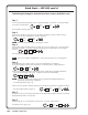
Quick Start — USP 405, cont’d Genlock menu 5 5 Advanced Configuration Genlock MENU Horz 128 NEXT Phase Horizontal phase • 0 thru 255 Sub 016 NEXT Subcarrier phase • 0 thru 255 Exit menu 6 Default Cycle 6 Genlock NEXT Exit MENU Input Configuration MENU Picture Adjustments menu Power on 60-369-0x Version x.xx Extron USP 405 2 sec. 2 sec.
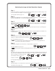
Optimizing the Image for High Resolution Outputs Step 1 Set the USP to output the crop pattern, then use the display's positioning controls to position the image so that you can see all sides on the display. To select the crop pattern: Default Cycle See "Test Pattern submenu" (page 2-17). MENU press 4 times NEXT press 4 times Step 2 If you are using a digital display, use the alternating pixels test pattern as a reference to adjust the phase and dot clock on the display device.
Quick Start — USP 405, cont’d Optimizing the Image for Standard Resolution Outputs (NTSC/PAL rates) Step 1 If you are using an analog CRT display, use the crosshatch test pattern as a reference to converge the display. To select the crosshatch pattern: press press Default Cycle MENU 4 times NEXT 4 times See "Test Pattern submenu" (page 2-17). Step 2 Set the USP to output the crop pattern, then use the display's positioning controls to position the image so that you can see all sides on the display.
Table of Contents Chapter 1 • Introduction ...................................................................................................... 1-1 About this Manual ............................................................................................................ 1-2 About the USP 405 ............................................................................................................ 1-2 What is the USP 405? ...............................................................................
Table of Contents, cont’d Top and bottom blanking submenu ................................................................................. 2-18 RGB Delay (Triple-Action Switching™) submenu ............................................................. 2-18 Enhanced mode submenu ................................................................................................. 2-18 PAL Film mode detect (2:2 pulldown detection) submenu ............................................. 2-18 Reset submenu ...........
Firmware Upgrade Installation ................................................................................. A-5 Serial Digital Interface (SDI) Card Installation ............................................... A-7 All trademarks mentioned in this manual are the properties of their respective owners. 68-541-01 Rev.
Table of Contents, cont’d iv USP 405 • Table of Contents
USP 405 1 Chapter One Introduction About this Manual About the USP 405 Features and Options
Introduction About this Manual This manual discusses how to install, configure, and operate the Extron USP 405 universal signal processor and how to operate the optional IR 801 infrared remote control (part #70-152-01). Throughout this manual the terms “USP”, “universal signal processor”, and “signal processor” are used interchangeably to refer to the same product.
• • Input 4 — One 4-pin mini-DIN connector accepts S-video, and one miniDIN connector outputs a buffered loop-through S-video signal. Input 5 (optional) — One BNC connector inputs the optional SDI (serial digital interface) signal.
Introduction, cont’d Options and accessories The USP 405’s optional equipment includes: • IR 801 remote control — The Extron IR 801 (part #70-153-01) is an infrared remote control which replicates all of the front panel controls of the USP 405 except the Menu and Next buttons. • SDI input card — Serial digital interface (SDI) input can be added to the USP 405 by the installation of an SDI input card (part #70-168-01).
USP 405 2 Chapter Two Installation and Operation Mounting the Scaler Rear Panel Features Front Panel Features Genlock and Vertical Interval Switching Optimizing the System Menus, Configuration, and Adjustments Image Adjustments Front Panel Security Lockout (Executive mode) IR 801 Infrared Remote Control Troubleshooting
Installation and Operation Mounting the Scaler Tabletop use The USP 405 signal processor comes with rack mounting brackets and rubber feet. For tabletop use, attach a self-adhesive rubber foot to each corner of the bottom of the unit. Rack mounting For rack mounting, do not install the rubber feet. Attach the provided rack mounting brackets to the USP 405 with machine screws, as shown below, then fasten the USP to the rack using the supplied machine screws.
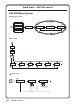
Sync Timing Source RS-232 Control IN G /Y R /RY 2 -23 RS T OU G E B Y N /B- L O C K S V H I SD -Y, B/R RG ,Y B-Y D B/H RG R-Y ,Y , B-Y R-Y VID Y O U T P U T S 5 4 I SD O IDE B-Y S-V ,Y , B-Y R-Y 3 B Y /B- 2 G /Y R /RY O IDE S-V S EO VID V 1 Extron USP 405 H 2A -Y, B/R RG I N T P U T S 0Hz 50-6 V -240 100 ,Y B-Y B RG MAX Non-linear Edit Station Extron RGB 112xi Betacam Tape Deck PC Computer SGI Computer VCR Example of the USP 405 being used as a scan converter RS-
Installation and Operation Rear Panel Features The rear panel of the USP 405, as shown below, contains all of the possible connectors available on the USP.
RGBHV RGBS/RGBcvS 2 2 Y VID R /R-Y G /Y H /HV V Y 2 VID R /R-Y G /Y H /HV V VID C Y B /B-Y R /R-Y G /Y H /HV V 2 C Y B /B-Y R /R-Y G /Y H /HV V HDTV Component Video VID S-video RGsB 2 C Y B /B-Y R /R-Y G /Y H /HV V 2 VID C Y B /B-Y R /R-Y G /Y H /HV V VID C B /B-Y C B /B-Y Composite Video Output of the SDI signal requires the SDI output card option.
Installation and Operation, cont’d 15 RGB or HDTV component output — Connect coaxial cables from these female BNC connectors to an RGB output device or to an HDTV component video device. Connect cables for the appropriate signal type, as shown here.
INPUTS FREEZE RGB FREEZE 1 UNIVERSAL COMPOSITE 2 PICTURE ADJUSTMENTS S-VIDEO SDI 4 5 3 CENTER SIZE BRT/CONT COL/TNT ADJUST ZOOM DETAIL MENU NEXT USP 405 UNIVERSAL SIGNAL PROCESSOR 1 2 3 4 5 6 7 8 9 10 11 12 13 14 15 16 17 18 USP 405 front panel 1 Infrared sensor — This sensor is used to receive infrared (IR) signals from the IR 801 remote control. See the “IR 801 Infrared Remote Control” section in this chapter.
Installation and Operation, cont’d 11 Color/Tint control button (Col/Tnt) — This button selects the color and tint adjustment for the output display. The adjustment is made using the horizontal Adjust and vertical Adjust adjustment knobs. The adjustment range of color is 0 to 127, and tint is 0 to 255. See the “Image Adjustments” section in this chapter. The Color/Tint control affects only composite video and S-video.
An oscilloscope is required for genlock setup, and a vectorscope is recommended. Waveform monitors of types other than a vectorscope may give the appearance that timing is adjusted correctly when it is 180 degrees out of phase. This results in incorrect colors or picture artifacts.
Installation and Operation, cont’d 8. View the horizontal phases again. If the phase difference is not zero, repeat steps 6 and 7 until the settings do not change. 9. Once the settings are stable, disconnect the oscilloscope, and reconnect the genlock cables. 10. Check the display(s) for proper colors and for undesirable artifacts in the image(s). Make adjustments as necessary. 11. If other USP 405s are part of this genlock daisy chain, connect the oscilloscope to each device, and repeat this procedure.
340 350 0 10 20 30 330 40 320 50 310 60 300 70 290 80 280 270 90 260 100 250 110 240 120 230 130 220 140 210 150 200 190 180 170 160 Vectorscope screen during horizontal phase adjustment The following diagram shows an example of a view of a vectorscope during adjustment of the color subcarrier phase (SC/H). The subcarrier phase should be aligned to 0º (indicated in the figure by the triangle).
Installation and Operation, cont’d Menus, Configuration, and Adjustments USP 405 configuration and adjustments can be performed by using the Windows-based control program (see chapter 3 for details) or by using the front panel controls and the menus that are displayed on the USP’s LCD screen. These menus are used primarily when the USP is first set up. Moving through menus by using front panel controls Menu button — Press the Menu button to activate menus and to scroll to the five main menus.
Power on 60-369-0x Version x.xx Extron USP 405 2 sec. Default Cycle 2 sec. MENU Input Configuration 10 sec. MENU Output Configuration 10 sec. MENU Memory Presets 10 sec. MENU Advanced Configuration 10 sec. MENU Genlock 10 sec. MENU Exit MENU NEXT Main menus Input Configuration The following flowchart provides an overview of the Input Configuration submenus and the options for each setting.
Installation and Operation, cont’d Input #2 submenu Rotate the horizontal Adjust ( ) knob while in the Input #2 submenu to select the appropriate video format (RGB, RGBcvS, YUVi, YUVp, Betacam 50, Betacam 60, HDTV, S-video, composite video) for input 2. The default for input 2 is Betacam 50. Input Phase submenu For RGB (input 1 and 2), HDTV, and YUVp (input 2) input sources, the pixel phase adjustment feature is used to eliminate unwanted noise by setting the sampling rate of the input source.
Available Scaler Output Resolutions and Rates Resolution 50 Hz 56 Hz 60 Hz 75 Hz Lock @ 50/60* 85 Hz 640 x 480 X X X X 800 x 600 X X X X 832 x 624 X X X 848 x 480 X X 852 x 480 X X 1024 x 768 X X X X X 1280 x 768 X X 1280 x 1024 X X X 1360 x 765 X X 1365 x 1024 X X 1400 x 1050 X X X HDTV 576p X X HDTV 720p X X HDTV 1080p X X HDTV 1080i X X X NTSC PAL * Rate is auto-selected based on input. The default resolution and rate is 640 x 480 @ 60 Hz.
Installation and Operation, cont’d Output Configuration MENU Memory Presets NEXT Save Preset 1 2 3 NEXT Erase Preset 1 2 3 NEXT Saving (SAVE) memory presets Erasing (erase) memory presets • Save the currently selected input's sizing and centering information. • Erase the currently selected input's saved sizing and centering information. • Up to 3 presets per input can be selected < > (N/A is the default) and saved. • Save a preset by pressing the NEXT button.
Advanced Configuration The following flowchart provides an overview of the Advanced Configuration submenus and the options for each setting. Edge Smoothing OFF Output Configuration Smooth edges Top Blanking Bot 021 030 • On (default) • Top blanking ranges from 000 (default) to 237 • Off NEXT NEXT MENU Top and Bottom Blanking* • Bottom blanking ranges 000 (default) to 237 Encoder filter setting Encoder Filter 06 Advanced Configuration NEXT • 0 thru 12 (default is 6) RGB Delay 0.
Installation and Operation, cont’d Top and Bottom Blanking submenu To remove noise or extraneous material such as closed captioning, remove scan lines at either the top or bottom of the screen by adjusting the top blanking or bottom blanking. Rotate the horizontal Adjust ( ) knob to adjust the top blanking from 0 to 237 lines. The default is 0. Rotate the vertical Adjust ( ) knob to adjust the bottom blanking from 0 to 237 lines. The default is 0.
Advanced Configuration Genlock MENU NEXT Horz 128 Phase Horizontal phase • 0 thru 255 Sub 016 NEXT Subcarrier phase • 0 thru 255 Exit menu From this menu, press the Next button to return to the Default menu cycle, or press the Menu button to return to the Input Configuration menu. Default Cycle NEXT Genlock Exit MENU Input Configuration MENU Image Adjustments Picture adjustments apply to scaled video output only; RGB signals are passed through without adjustments.
Installation and Operation, cont’d The Adjust knobs have no mechanical limits to their rotation. • Centering: Horizontal (Horz) adjusts horizontal positioning. Vertical (Vert) adjusts vertical positioning. • Sizing: Horizontal (Horz) adjusts horizontal sizing. Vertical (Vert) adjusts vertical sizing. • Brightness/Contrast: Brightness adjusts from 0 to 63. Contrast adjusts from 0 to 255. • Color/Tint: Color adjusts from 0 to 127. Tint adjusts from 0 to 255.
IR 801 Infrared Remote Control The optional IR 801, shown at right, replicates all of the front panel controls except the Menu and Next buttons. If Executive mode is enabled, selections and adjustments can still be made using the IR 801, but you must use the USP 405’s front panel or the Windows-based control program (via an RS-232 device) to configure and program the USP. See chapter 3, “Serial Communication”, for details. While Executive mode is active, adjustments can still be made using the IR 801.
Installation and Operation, cont’d Horizontal and vertical filtering • The horizontal filter adjustment button will enhance image detail. Pressing the up arrow button will increase the horizontal filtering, and pressing the down arrow button will decrease the horizontal filtering. The range of adjustment is 0 through 7. • The vertical filter adjustment button will reduce image flicker while maintaining image sharpness.
Operating problems The table below shows some common operating problems and their solutions. Problem Cause Solution No image appears. The input signal is incompatible. Make sure that the input signal is the appropriate type and frequency for the given input. Freeze mode was entered when the image was black. Deactivate freeze mode. The scaled output rate is too high for the display. Freeze mode is on. Change the scaled output to a compatible resolution. The image is flashing.
Installation and Operation, cont’d 2-24 USP 405 • Installation and Operation
USP 405 3 Chapter Three Serial Communication RS-232 Programmer’s Guide Control Software for Windows Labeling Buttons on the USP 405 Setting the Output Rate Using the Per Input Feature
Serial Communication The USP 405 can be remotely controlled via a host computer or other device (such as a control system) attached to the rear panel RS-232 connector. The control device (host) can use either Extron’s Simple Instruction Set (SIS) commands or the graphical control program for Windows. The signal processor uses a protocol of 9600 baud, 1 stop bit, no parity, and no flow control.
Using the command/response tables The command/response tables starting on the next page list valid command ASCII codes, the USP 405’s responses to the host, and a description of the command’s function or the results of executing the command. Uppercase and lowercase characters may be used interchangeably in the command field. The ASCII to HEX conversion table at left is for use with the command/response tables.
Serial Communication, cont’d Command/response table for SIS commands Command ASCII Command Response (host to USP) Additional description (USP to host) Input selection Select video Example: Select video only ! X1 2! X1 & X8 \ In• X1 All In 02All In• X1 Vid Video input X1 . Select input 2 video. Video input X1 . Typ Specify input 2 video type. Input 2 video type Set video type, input 2 only Example: View video type X8 3\ Typ 3 Specify input 2 type as YUVp.
Command/response table for SIS commands (continued) Command ASCII Command Response (host to USP) Additional description (USP to host) Horizontal size Increase the horizontal size Decrease the horizontal size +: -: Hsz Hsz Widen the picture. Make the picture narrower. +; -; Vsz Vsz Make the picture taller. Make the picture shorter.
Serial Communication, cont’d Command/response table for SIS commands (continued) Command View the freeze status Example: ASCII Command Response (host to USP) (USP to host) F F X9 Additional description Show the freeze status. 0 Pixel phase Set a specific pixel sampling phase Example: X1 * X21 U Phs X1 1*17U X21 1Phs17 Specify the pixel sampling phase. Set the sample phase to 17 for input 1. Increment sampling value X1 +U X1 Phs X21 Increase the phase value.
The syntax for setting a special function is X? * X! # where X? is the function number and X! is the value. To view a function’s setting, use X? # where X? is the function number. In the following table the values of the X? variable are different for each command/function. These values are given in the far right column. Command/response table for special function SIS commands Command ASCII Command Response (host to USP) X! values (USP to host) and additional descriptions Dly Dly35 0 = 0.
Serial Communication, cont’d Control Software for Windows The included Extron USP 405 Control Program for Windows offers another way to control the USP 405 via RS-232 connection in addition to the Simple Instruction Set commands. The control program’s graphical interface includes the same functions as those on the signal processor’s front panel and some additional features that are only available through the Windows-based software.
3. Click the I/O Config button to configure the inputs from the I/O Configuration Window, shown below. Using the help program For information on program features, press the F1 computer key, or click on the Help menu from within the USPDDS Control Program, or double-click on the USPDDS Help icon in the Extron Electronics group or folder. For explanations of buttons or functions, click the tabs in the help screen to reach the desired screen.
Serial Communication, cont’d 2. Under System selection, choose the System 7SC. This selection creates the correctly sized labels for the USP’s buttons. The button label editing area changes to reflect the number and arrangement of buttons on the device. 3. Using normal Windows controls, you can create and print labels that can be cut out and placed in the label windows on the front panel of the USP.
Setting the Output Rate Using the Per Input Feature Using the Per Input feature, each input (1 through 5) can have a different output rate associated with it. This feature must be initially configured through the USP 405’s Control Program for Windows. The initial configuration is stored in memory, and can be recalled whenever the output resolution is set to Per Input via either RS-232, the Control Program, or the USP’s front panel controls.
Serial Communication, cont’d 3-12 USP 405 • Serial Communication
USP 405 A Appendix Appendix Specifications Part Numbers and Accessories Firmware Upgrade Installation Serial Digital Interface (SDI) Card Installation
Appendix Specifications Video Gain ................................................ Unity Crosstalk ....................................... -50 dB @ 5 MHz Video input Number/signal type ................... 1 RGBHV/RGBS/RGsB computer video with 1 local monitor loop-through 1 RGBHV/RGBS/RGsB, RGBcvS computer video, component video, S-video, or composite video 1 S-video 1 composite video 1 SDI (optional) Connectors ................................... (2) 15-pin HD female ..............
Connectors ................................... 1 x 6 BNC female (RGB, HD component video) (1) 15-pin HD female (RGB, HD component video) 3 BNC female (component video) (1) 4-pin mini DIN (S-video) 1 BNC female (composite video) 1 BNC female (optional SDI digital component video) Nominal level ............................... 1 Vp-p for Y of component video and S-video, and for composite video 0.7 Vp-p for RGB and for R-Y and B-Y of component video 0.3 Vp-p for C of S-video Minimum/maximum levels .......
Appendix, cont’d Product weight USP 405 .............................. USP 405, SDI input ........... USP 405, SDI output ........ USP 405, SDI in & output Shipping weight USP 405 w/SDI in & output All other models .............. Vibration ....................................... Listings .......................................... Compliances ................................. MTBF ............................................. Warranty ....................................... 6.3 lbs (2.9 kg) 6.4 lbs (2.
Firmware Upgrade Installation In some cases the USP 405’s firmware may require replacement with an updated version. There are four user-replaceable firmware chips: U60 — the main microcontroller, U24, U67 and U68. Both U67 and U68 are replaced as a pair. The numbers are printed on the circuit board. We recommend that you send the unit in to Extron for service and updates. CAUTION Changes to firmware must be performed by authorized service personnel only.
Appendix, cont’d U24 U60 U68 U67 Locating the four firmware IC chips 5. After you are electrically grounded, the U67 and U68 IC chips (which must be replaced as a pair) may be removed by grasping each chip firmly with your fingers and pulling it out, then continuing to step 8. Removal of the U60 and U24 IC chips requires a PLCC IC puller tool. To remove either chip, align the hooks of a PLCC IC puller tool with the slots located in opposite ends of the firmware chip. 6.
10. Replace the top cover on the USP 405, and fasten it with the screws that were removed in step 3. 11. Rack or furniture mount the scaler, and reconnect the AC power cord. Serial Digital Interface (SDI) Card Installation The optional SDI input and output cards may be installed in the USP 405 if it does not already have an input or output for a serial digital interface signal. We recommend that you send the unit to Extron for service and updates.
Appendix, cont’d 4. If installing the SDI input card, locate the SDI input card standoff situated near the middle rear portion of the main circuit board (looking from above with the front panel nearest to you). See the following picture.
5. If the rear panel SDI connector opening is still covered, remove the plastic cover and position the SDI card at an angle with the SDI connector protruding from the rear SDI connector opening. 6. The SDI input card has a 20-pin socket on the underside that should align with the 20 pins on the main circuit board. Be sure to align the pins properly, in order to prevent bending the pins, before pressing the SDI card firmly in place against the standoff.
Appendix, cont’d 7. For the SDI input card installation, insert the card’s installation screw through the SDI card’s mounting hole and gently tighten it into the standoff. See the picture below. Installed SDI input card For the SDI output card installation, the card should be positioned in place as shown below. J23 1 2 Installed SDI output card 3 J23 A-10 1 3 8. Install the SDI connector’s hex nut and keep the SDI card from twisting as the nut is tightened. 9.
FCC Class A Notice Note: This equipment has been tested and found to comply with the limits for a Class A digital device, pursuant to part 15 of the FCC Rules. These limits are designed to provide reasonable protection against harmful interference when the equipment is operated in a commercial environment. This equipment generates, uses and can radiate radio frequency energy and, if not installed and used in accordance with the instruction manual, may cause harmful interference to radio communications.
www.extron.com Extron Electronics, USA Extron Electronics, Europe Extron Electronics, Asia Extron Electronics, Japan 1230 South Lewis Street Anaheim, CA 92805 USA 714.491.1500 Fax 714.491.1517 Beeldschermweg 6C 3821 AH Amersfoort The Netherlands +31.33.453.4040 Fax +31.33.453.4050 135 Joo Seng Road, #04-01 PM Industrial Building Singapore 368363 +65.6383.4400 Fax +65.6383.4664 Kyodo Building 16 Ichibancho Chiyoda-ku, Tokyo 102-0082 Japan +81.3.3511.7655 Fax +81.3.3511.