USP 507 Universal Signal Processor 68-1796-01 Rev.
Precautions Safety Instructions • English Warning This symbol is intended to alert the user of important operating and maintenance (servicing) instructions in the literature provided with the equipment. Power sources • This equipment should be operated only from the power source indicated on the product. This equipment is intended to be used with a main power system with a grounded (neutral) conductor. The third (grounding) pin is a safety feature, do not attempt to bypass or disable it.
声明 所使用电源为 A 级产品,在生活环境中,该产品可能会造成无线电干扰。在这种情况下,可能需要用户对其干扰采取切实可行的措施。 FCC Class A Notice This equipment has been tested and found to comply with the limits for a Class A digital device, pursuant to part 15 of the FCC Rules. Operation is subject to the following two conditions: (1) this device may not cause harmful interference, and (2) this device must accept any interference received, including interference that may cause undesired operation.
Table of Contents Chapter One • Introduction . ..................................................................................................... 1-1 About this Manual ..................................................................................................................... 1-2 About the USP 507 . .................................................................................................................... 1-2 Definitions . ...............................................................
Table of Contents, cont’d Input configuration ................................................................................................................... 3-7 Output configuration . .............................................................................................................. 3-8 Image capture/recall .................................................................................................................. 3-9 To capture an image: ...............................................
Chapter Five • USP 507 Software ........................................................................................... 5-1 Installing and Starting the Signal Processing Products Control Program ..................................................................................................... 5-2 Installing the program .............................................................................................................. 5-2 Starting the program ................................................
Table of Contents, cont’d Control Pages .............................................................................................................................. 6-13 User Control page .................................................................................................................... 6-13 Memory/Input Presets page ................................................................................................... 6-14 PIP Setup/PIP Presets page ..........................................
USP 507 1 Chapter One Introduction About this Manual About the USP 507 Definitions Features
Introduction About this Manual This manual contains installation, configuration, and operating information for the Extron USP 507 Universal Signal Processor. It covers basic installation, and configuring and operating the device using the front panel controls and Simple Instruction Set (SIS™) commands. It also describes how to load and start up the Windows®-based Signal Processing Products Control Program (SPPCP) and how to connect to the built-in HTML pages, for operating the processor.
Definitions The following terms are used throughout this manual: EDID — Extended Display Identification Data. A communications protocol or instruction set developed by VESA (Video Electronics Standards Association) for the identification of display devices to computers using the DDC (Display Data Channel) transmission standard. DVI — Digital Visual Interface. The digital video connectivity standard that was developed by DDWG (Digital Display Working Group).
Introduction, cont’d Features Inputs: Two RGB or HD component video on 15-pin HD connectors; configurable input on BNCs for RGB, HD/SD component video, S-video, or composite video; component video, S-video, or composite video on BNCs; S-video or composite video on BNCs; DVI-D; and optional SDI/HD-SDI.
Auto Input Memory — When activated, the USP 507 automatically stores size, position, and picture settings based on the incoming signal. When the same signal is detected again, these image settings are automatically recalled from memory. EDID emulation — The USP 507 provides a means for specifying the rate of the incoming DVI or VGA signal through the RS-232 serial port. EDID emulation allows proper communication with the video source.
USP 507 2 Chapter Two Installation U/L Safety Requirements Mounting the USP 507 Rear Panel Features and Connections Powering Up Resetting the Unit with the Reset Button
Installation, cont’d Installation UL/Safety Requirements The Underwriters Laboratories (UL) requirements listed below pertain to the safe installation and operation of this universal signal processor. Important safety instructions 2-2 1. Read these instructions. 2. Keep these instructions. 3. Heed all warnings. 4. Follow all instructions. 5. Do not use this apparatus near water. 6. Clean only with a dry cloth. 7. Do not block any ventilation openings.
Mounting the USP 507 If the USP 507 is to be rack mounted, it is important to mount it before cabling it. Four rubber feet are included with the unit. Install the feet only if the unit is to be mounted on a tabletop (see “Tabletop placement” below). Tabletop placement For tabletop placement, install the self-adhesive rubber feet/pads (provided) onto the four corners of the bottom of the device.
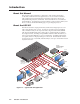
Installation, cont’d Rear Panel Features and Connections 1 I N P U T 100-240 VAC 2A MAX 50-60Hz 1 R /RY G/Y VID B/C 4 B-Y V R-Y VID 5 /Y VID /Y RGB/R-Y, Y, B-Y 2 RGB/R-Y, Y, B-Y 2 HDSDI/ SDI 7 6 H/HV B-Y /C DVI-D C 5 4 3 15 10 7 3 G /Y R /R-Y O U T P U T B /B-Y RS-232 DVI OUT RESET LAN H V 6 S 13 12 9 8 AUX SW FOLL0W MTP RGB/R-Y, Y, B-Y 14 11 Figure 2-2 — USP 507 rear panel features a AC power connector b RGB/YUV-HD VGA connectors (inputs 1 and 2) c Universa
Output, user interface, and control connections h RGB/YUV-HD BNC connectors — Connect a display to these for RGB or HD component video output. RGsB/Component Video (Y, R-Y, B-Y) RGBS video RGBHV R /R-Y G /Y B /B-Y R /R-Y G /Y H/ HV V S H/ HV V B /B-Y S R /R-Y G /Y B/ B-Y H/ HV V S i RGB/YUV-HD 15-pin VGA connector — Connect a display to this for RGB or HD component video output.
Installation, cont’d Installation and cabling Step 1 — Mount the unit Turn off or disconnect all equipment power sources and rack mount the USP 507. See page 2-3. Step 2 — Connect inputs Connect inputs from video sources to the applicable connectors marked “Inputs” (see page 2-4, b to g for connector types). Step 3 — Connect outputs Connect video output devices to the applicable connectors marked “Outputs” (see page 2-5, h to k for connector types).
Powering Up When applying power to the USP 507, the unit undergoes a start-up self testing sequence (see image below) and then the LCD displays the default display cycle. Default display cycle When in use but not in any menu mode, the LCD screen defaults to cycling through the input/output configuration currently installed. The displayed content may vary, depending on the input video signal type. See figure 2-3 for a typical default display cycle. Apply power 10 sec. Extron USP 507 v1.xx 3 sec.
Installation, cont’d USP 507 Reset Mode Summary Mode Activation 1 N After a mode 1 reset is performed, update the USP 507 firmware to the latest version. The reset tofactory intsled firmware is temporary. When power is cycled, the unit uses the last installed firmware. Do not operate the firmware version that results from this mode reset. If you want to use the factory default firmware, you must upload that version again. See page 6-10 for details on uploading firmware.
USP 507 3 Chapter Three Front Panel Operation Front Panel Overview Switching Inputs Special Function Button Operation Button Backlighting The USP 507 Menu System Setting the Front Panel Locks (Executive Modes) Setting Up the USP 507 to Work with a Matrix Switcher Setting Up the USP 507 to Work with an Auxiliary Audio Switcher
Front Panel Operation Front Panel Overview ADJUST INPUTS 1 2 3 4 5 6 MUTE AUTO IMAGE SIZE BRIGHT /CONT DETAIL MENU FREEZE PIP PRESET POSITION COLOR /TINT ZOOM /PAN NEXT 7 USP 507 UNIVERSL SIGNAL PROCESSOR 2 1 3 4 6 5 7 Figure 3-1 — Front panel features a Front panel configuration port — Connect a control system or computer to this (RS-232) port, using an optional 9-pin D to 2.5 mm mini jack TRS RS-232 cable, part 70-335-01 (see below).
f Menu navigation buttons — These two buttons give access to menu commands. See “The USP 507 Menu System” section in this chapter. Menu button — This button, always lit amber, gives direct access to a series of seven menus. Next button — This button, always lit amber, allows page changes within each one of the menus, and to exit the menu cycle. g Adjust knobs — These two knobs are used with the picture control buttons and the menu navigation buttons to adjust settings.
Front Panel Operation, cont’d Front Panel Operation The USP 507 Menu System The USP 507 can be configured using the menu system, via the Extron Simple Instruction Set (SIS™) of commands through an RS-232 or LAN connected PC, or via the Extron software program, SPPCP. N For SIS commands and SPPCP configuration methods see chapters 4 and 5.
USP 507 • Front Panel Operation 3-5 Menu Rotate either to select a preset to save current settings to. Save Preset <02> Next Rotate either to select a preset to recall settings. Recall Preset Next User Presets Menu Menu Rotate either to adjust Sync Polarity values. Sync Polarity H Neg V Pos Next Rotate either to adjust Output type value. Output Type RGBHV Next Rotate to adjust Resolution value Rotate to adjust Refresh rate. Resol 1024x768 Refresh 60.
Front Panel Operation, cont’d Using the menus To configure the USP 507 using any of the menus, do the following: Press the Menu button repeatedly to get to the desired configuration menu. 1. 2. Press the Next button repeatedly to go to the desired submenu. 3. The LCD shows the current values. Observe the LCD and rotate either (or both) Adjust knob to change the values as desired. N Pressing the Menu button within any level returns the user to the current top level menu.
Input configuration Within this menu any of the seven inputs can be configured. Each input has different settings depending on the signal format. Consult the tables below for signal formats per input and possible adjustments per signal format. To configure inputs: 1. From the top level Input Configuration menu press the Next button to bring up the input selection screen. The active input is displayed on the LCD with current signal format.
Front Panel Operation, cont’d Output configuration Within this menu an outputs resolution, refresh rate, output signal type, and sync polarity can be selected and adjusted. Refer to the table below for applicable resolution and refresh rates. Press Next to bring up the Resolution submenu. In this submenu, the 1. resolution and refresh rate can be adjusted. 2. Rotate the left front panel knob ([) to adjust the resolution value, and rotate the right knob ({) to adjust the refresh rate.
Image capture/recall Within this menu, the currently displayed image can be captured and saved to the USP 507 memory. This image or any other saved image can then be recalled and output to the active display at a later time. The recalled image can be displayed at the front of or behind an active video signal. To capture an image: 1. Press Next to enter the save menu, the LCD displays “Save Image: ”. Use either Adjust knob to scroll through 16 image names, (IMG01.bmp through IMG16.
Front Panel Operation, cont’d Step 1 UNDO/ MENU CLEAR Press twice Recall to back: NEXT UNDO/ MENU CLEAR Press three times LCD screen displays LCD screen displays Recall to front: NEXT ADJUST LCD screen displays Rotate either Adjust knob. Recall: IMG05.BMP Step 2 LCD screen displays MENU Press Recalling Image Please wait then NEXT IMG05.BMP Recalled To remove an image from the display: Press Next twice. The LCD displays “Recall to back: ”.
With the applicable input showing, rotate the right Adjust knob ({) to turn the Auto-Image on or off. Input EDID Press Next to go to the next sublevel (Input EDID), or 3. 1024x768 60.0Hz press Next repeatedly to get to any applicable level. At each level, rotate the adjustment knobs (right only or both) as needed to change the settings to the desired value. N The Input EDID setting adjustment applies only to the VGA and DVI inputs. Refer to figure 3-5 for resolution and refresh rate details.
Front Panel Operation, cont’d View comm settings Within this menu the current IP settings are only viewable. To make any adjustments the “hidden” Edit Comm Settings menu must be accessed (see below). 1. Press Next to go through each sublevel to view the following: serial port (baud rate and communication type), MAC address (cannot be changed), DHCP status (on or off), IP address, subnet mask, and gateway address. 2. Press Next or Menu to return to the View Comm Settings menu.
Scan converter configuration This menu is available only when a scan converter board is installed. Within this menu horizontal and vertical image size and centering can be configured, output format and output standard chosen, and flicker, horizontal, and encoder filters set. Press Next to enter the first sublevel, Horizontal and Vertical size. The current 1. settings are displayed. (2048 pixels is the default setting) 2.
Front Panel Operation, cont’d Setting Up the USP 507 to Work with a Matrix Switcher The Sync to Matrix tool is a powerful software tool that can simplify the control system necessary when using an Extron matrix switcher and an USP 507. The “Sync to Matrix” script can sense when a new tie that is made on the matrix is routed to the USP 507 and automatically recalls the input preset associated with the input on the matrix switcher.
Input 1 Output 1 Input 3 USP 507 #1 Output to display Input 2 Output 2 Input 3 USP 507 #2 Output to display Input 3 Output 3 Input 4 Output 4 Input 5 Output 5 Input 3 USP 507 #6 Output to display Input 6 Matrix Switcher Output 6 (optional) (optional) Input 63 Output 63 Input 64 Output 64 Figure 3-9 — Multiple USP 507’s connected to a matrix switcher 3. On the USP 507, configure the input as follows: a. Switch to input 3 on the USP 507. b.
Front Panel Operation, cont’d Setting Up the USP 507 to Work with an Auxiliary Audio Switcher An auxiliary switcher, such as an Extron SW 8A, can be connected to the USP 507 for audio routing, and controlled via the rear panel 9-pin D-sub Aux Sw Follow (RS-232) port (see n on figure 2-2). When the USP 507 switches inputs by RS-232, IP, or front panel, the USP 507 sends the corresponding switch command (SIS: X! !) via the Aux Sw Follow port to the auxiliary switcher.
USP 507 4 Chapter Four SIS™ Programmer’s Guide RS-232/RS-422 Link Ethernet (LAN) Port Host-to-Processor Instructions Processor-Initiated Messages Processor Error Responses Using the Command/Response Tables for SIS™ commands Using the Command/Response Table for IP SIS Commands
SIS Programmer’s Guide The USP 507 can be operated and configured using Simple Instruction Set™ (SIS™) commands input via a PC connected to the top RS-232 port on the rear panel or the Ethernet port. See m on page 2-4, and Appendix B for wiring details. RS-232/RS-422 Link The USP 507 has one rear port (the upper serial port) and one front port (see a on page 3-2) that can be used for serial control. All ports enable use of SIS commands and the Windows®-based control software.
Connection timeouts The Ethernet link times out after a designated period of time of no communications. By default, this timeout value is set to five minutes but the value can be changed. N Extron recommends leaving the default timeout at five minutes and periodically issuing the Query (Q) command to keep the connection active. If there are long idle periods, Extron recommends disconnecting the socket and reopening the connection when another command must be sent.
SIS Programmer’s Guide, cont’d Reconfig] The processor sends the Reconfig message whenever a new resolution is applied. N Response given is seen via RS-232 connection only. Exen] The processor initiates the Exe message when Executive mode is toggled on or off from the front panel. “n” is the Executive mode status: 1 = on, 0 = off. Processor Error Responses When the USP 507 receives an SIS command and determines that it is valid, it performs the command and sends a response to the host device.
Symbol definitions ] = Carriage return with line feed ¦ or } = Carriage return with no line feed • = Space E or W = Escape key X! = Input selection, 1 to 7 X# = Input video format: 1 = RGB (default) 2 = YUVp/HDTV 3 = RGBcvS 4 = YUVi 5 = S-video 6 = Composite video 7 = SDI 8 = HD-SDI 9 = DVI 10 = Auto detect X$ = H/V start — 0 to 255 (default midpoint = 128) X^ = Pixel phase — 0 to 31 (default = 16) X& = Total pixels — (±512 of the default value) X* = Active pixels — (±512 of
SIS Programmer’s Guide, cont’d X2! = Scaler resolution: 1 = 640 x 480 2 = 800 x 600 3 = 852 x 480 4 = 1024 x 768 5 = 1024 x 852 6 = 1024 x 1024 7 = 1280 x 768 8 = 1280 x 800 9 = 1280 x 1024 10 = 1360 x 765 11 = 1360 x 768 12 = 1365 x 768 13 = 1366 x 768 14 = 1365 x 1024 15 = 1440 x 900 16 = 1400 x 1050 17 = 1680 x 1050 18 = 1600 x 1200 19 = 1920 x 1200 20 = 480p 21 = 576p 22 = 720p 23 = 1080i 24 = 1080p 25 = 2048 x 1080 X2@ = Output refresh r
Command Response Table for SIS Commands Command ASCII command (host to processor) Response (processor to host) Additional description Input Switching and Configuration Input selection Select input X! ! InX!] View current input ! X!] Select video from input X!. View currently selected input source. Set format X!*X#\ TypX!*X#] Set input X! to video format X#. View format X!\ X!*\ X#] AtypX!*X#] View video format of input X!. View actual video format auto detected on input X!.
SIS Programmer’s Guide, cont’d Command ASCII command Response (host to processor) (processor to host) Specify a value E X^PHAS} PhasX!*X^] Increment value E+PHAS} E-PHAS} EPHAS} PhasX!*X^] Additional description Pixel phase Decrement value View value Set pixel phase to specified value for active input. Increase value. PhasX!*X^] X^] Decrease value. Show pixel phase.
Command ASCII command Response (host to processor) (processor to host) E X1%COLR} E+COLR} E-COLR} ECOLR} ColrX!*X1%] E X1%TINT} E+TINT} E-TINT} ETINT} Additional description Color Specify a value Increment value Decrement value View value ColrX!*X1%] Set color level to X1%. Increase value. ColrX!*X1%] Decrease value. X1%] Show color level. TintX!*X1%] Set tint level to X1%. Increase value.
SIS Programmer’s Guide, cont’d Command ASCII command Response Additional description (host to processor) (processor to host) E X1&HSIZ} E+HSIZ} E-HSIZ} EHSIZ} HsizX!*X1&] E X1&VSIZ} E+VSIZ} E-VSIZ} EVSIZ} VsizX!*X1&] X1&] Make image shorter. Main window E1XY} Wxy1,*X1^*X1^*X1&*X1&] PIP window E2XY} Wxy2,*X1^*X1^*X1&*X1&] View position and size of main window. View position and size of PIP window.
Command ASCII command Response Additional description (host to processor) (processor to host) Set output rate E X2!*X2@RATE} RateX2!*X2@] View output rate ERATE} X2!*X2@] Set polarity E X2#OPOL} OpolX2#] View polarity setting EOPOL} X2#] Set output polarity for RGBHV ouput. Show current output polarity. E X2$OSYN} EOSYN} OsynX2$] Set output sync format. X2$] Show current output sync format.
SIS Programmer’s Guide, cont’d Command ASCII command (host to processor) Response (processor to host) Additional description Scan converter horizontal size Specific value Increase size Decrease size View ESX1&HSIZ} ES+HSIZ} ES-HSIZ} ESHSIZ} HsizSX1&] HsizSX1&] Set horizontal size to X1&. Widen image. HsizSX1&] X1&] Make image narrower. VsizSX1&] Set vertical size to X1&. Make image taller. Horizontal size is X1&.
Command ASCII command Response Additional description (host to processor) (processor to host) Enable E1AMEM} Amem1] Disable E0AMEM} Amem0] View setting EAMEM} X1)] Set auto memory on. Previous settings for incoming signal are auto recalled. Set auto memory off. Default settings are always used unless input preset is recalled manually. View auto memory status. E X2)TEST} ETEST} TestX2)] X2)] Select test pattern X2). View selected test pattern. Enable 1F Frz1] Freeze selected input.
SIS Programmer’s Guide, cont’d Command ASCII command Response Additional description (host to processor) (processor to host) PIP input select E X!PIP} PipX!] PIP off E0PIP} EPIP} Pip0] Turn PIP on and display input X!. Turn PIP off. X! ] View PIP window selection. Picture in Picture PIP on/off View PIP status N When PIP is enabled, all picture control commands apply to the image in the PIP window. Swap PIP % Tke] Swap content between main and PIP window.
Command ASCII command (host to processor) Response (processor to host) Additional description Image Capture/Recall Image capture/recall to USP 507 flash memory Save image E 0*filenameMF} Ims*filename] Recall image to foreground E 0*filenameRF} Imr0filename] Recall image to background E 1*filenameRF} Imr1filename] Mute image E 0*0RF} Imr0] Current image E RF} X3*filename] Saves currently displayed image to memory under the designated name. Recalls image to be displayed in foreground.
SIS Programmer’s Guide, cont’d Using the Command/Response Table for IP SIS Commands Symbol definitions X10) = Switcher name, up to 240 alphanumeric characters. N The following characters are invalid in the name: {space} ~ , _ @ = ` [ ] { } < > ‘ “ ; : | \ and ?.
USP 507 • SIS Programmer’s Guide 4-17 N X7)] Ipn•X10)] WX10(CU| EX10(CU} ECU} E•CU} EX11^DH} EDH} WDH| WX11^DH| W•CU| WCU| W•CA| E•CA} {space} ~ , _ @ = ` [ ] { } < > ‘ “ ; : | \ and ?.
4-18 USP 507 • SIS Programmer’s Guide EX12%*X12&*X13)* X13#*X13!CE} EX12%CE} EX12%*X13%,X13^, X13&,X13*CP} EX12%CP} EX12%*X13(CY} EX12%CY} EX12%*X14),X14!CF} EX12%CF} Emm #####] WX12%%2AX12&%2AX13) %2AX13#%2AX13!CE| WX12%CF| WX12%%2AX14)%2CX14!CF| WX12%CY| WX12%%2AX13(CY| WX12%CP| WX12%%2AX13%%2AX13^ %2AX13&%2AX13*CP| X14),X14!] CpnX12%•CceX12&,X13),X13#, X13!] # = byte count (for L) or # = a single ASCII character expressed in decimal form (for D). The parameter is case sensitive.
USP 507 • SIS Programmer’s Guide 4-19 WX12%CD| EX12%CD} Read redirect mode Epath/directory/CJ} E/CJ} E~CJ} ECJ} Dir•path/directory/] Dir•/] W%2FCJ| X14@] W1TC| Wpath%2Fdirectory%2FCJ| X14@] Pti1*X14@] W1%2AX14@TC| Pti0*X14@] W0TC| W0%2AX14@TC| X14#,X14$,X13!] Additional description N # = byte count (for L) or # = a single ASCII character expressed in decimal form (for D). The parameter is case sensitive. Byte count is 0 to 32767, (default = 0).
4-20 USP 507 • SIS Programmer’s Guide Efirst char in filename List selected files from current directory and below Wfirst char in filename first char in extensionDF| Wfirst char in extensionDF| Efirst char in extensionDF} List selected files from current directory and below first char in extensionDF} WLF| ELF} List selected files in directory/subdirectories using file extension only. List selected files in directory/subdirectories using filename and extension.
USP 507 5 Chapter Five USP 507 Software Installing and Starting the Signal Processing Products Control Program Using the Program
USP 507 Software Installing and Starting the Signal Processing Products Control Program The USP 507 can be operated via the Windows®-based Signal Processing Products Control Program (SPPCP). This program is on the Extron Software Products DVD (included with the unit) or available at www.extron.com. Install and run this program on a Windows-based PC connected to either of the serial ports or the Ethernet port. See page 2-4 for connection information. The program cannot be run from the DVD.
3. If you selected TCP/IP tab in step 2, the TCP/IP Connection window appears. a. Examine the IP Address field, which displays the last IP address entered, or the drop-down box which lists the most recently used IP addresses. If listed, select the applicable IP address, or enter the correct IP address in the field. N 192.168.254.254 is the factory-specified default IP address. b. If the unit is password protected, enter the appropriate administrator or user password in the Password field. c.
USP 507 Software, cont’d Control program menus File menu Click on this to open a drop-down menu displaying six selectable options: Connect, Disconnect, Save Configuration..., Restore Configuration..., File Manager, and Exit. • Connect — Select this to reconnect the USP 507 (or connect a new device) when it has been disconnected from the Signal Processing Products Control Program. Then follow the steps for “Starting the program” on page 5-2.
Tools menu Click on this to open a drop-down box displaying nine selectable options: Data View/Trace Window... Executive Mode, Sync Scaler to Matrix Switcher..., System Settings..., Reset, and Update Firmware.... • Data View/Trace Window... — Select this to open a separate window in which the transmit and receive (Tx/Rx) data between the control software on the host PC and the USP 507 can be viewed in ASCII format (see figure at right).
USP 507 Software, cont’d • System Settings... — Select this to open a secondary window. This allows changes to be made to various device settings: IP and RS-232 connections, date/time, and passwords. Select the applicable tab, change the settings as desired, and click Submit to make the changes effective. N Changing the IP address may result in loss of connection to the LAN. Only the baud rate can be changed when selecting the RS-232 tab.
3. Select the connection method. If connecting by TCP/IP, enter the IP address and, if needed, the password. Click Connect. If the device connects correctly the device name will appear in green alongside a check mark. 4. Click Browse. A dialog box opens to enable a search for the devicespecific firmware file (with the file extension “.S19”) previously saved to the connected PC. 5. In the dialog box, browse to the file location. Click on the file then click Open.
USP 507 Software, cont’d 6. Click Begin. The file uploads to the USP 507 and the upload progress can be seen on the Total Progress bar. 7. When the file upload is complete (after file verification and the USP 507 restarting), click on the X at top right, or on File > Exit to exit the Firmware Loader. The SPPCP window restores itself. 8. Connection to the USP 507 must be reestablished since the connection is lost during firmware upload.
• Unit Info... — Select this to open a dialog box with information about the connected device. The box shows the part number, the name, model description, currently installed firmware version and build, and the device’s internal temperature. Control tab The Control tab displays the current configuration of the USP 507, with numbered boxes representing the video inputs.
USP 507 Software, cont’d • User Presets — A user preset saves specific settings for color, brightness, detail, size, zoom and pan, and centering and up to 16 user presets per input are available. These settings can then be recalled and applied to an applicable input. Select a preset number and click Save or Recall as desired. • PIP Presets — A PIP preset saves specific layout settings for location and size of the PIP and main windows. These settings can be recalled and applied to any applicable input.
Advanced Settings tab The Advanced Settings tab allows advanced functions to be configured. These include test pattern selection and advanced features, used primarily during initial setup. Figure 5-5 — The Advanced Settings tab screen • Test Pattern — Select any of the 14 test patterns to aid setting up an output display device. A small thumbnail of the pattern is shown on the tab (see above). Select Off where a test pattern is not needed.
USP 507 Software, cont’d Scan Converter tab N The Scan Converter tab appears only if the optional scan converter output board is installed in the USP 507. The Scan Converter tab allows viewing and changing of the configuration settings for the optional scan converter output board. Figure 5-6 — The Scan Converter tab screen • Picture Adjustments — The Picture Adjustments and Image Filter sections of the Scan Converter tab allow adjustments to be made to the image settings of the scan converted output.
Image Capture tab The Image Capture tab allows capturing, saving, recalling, and deletion of displayed images. Images can be recalled to the foreground or background as desired. The size of each saved image is shown, and the amount of free space (internal memory) on the USP 507 for saving images to is given. The status of the currently displayed image is also given.
USP 507 6 Chapter Six HTML Operation Accessing the Web Pages System Status Page Configuration Pages File Management Page Control Pages Images Page
HTML Operation The USP 507 can be controlled and operated through its Ethernet port, connected via a LAN or WAN, using a Web browser such as Microsoft® Internet Explorer®. The browser displays the unit’s factory-installed Web pages, which provide an alternative means of viewing and operating the device. N If the Ethernet connection to the USP 507 is unstable, try turning off the proxy server in the Web browser.
The USP 507 checks several possibilities, in the following order, and then responds accordingly: • Does the address include a specific file name, such as “192.168.254.254/file_name.html”? If so, the unit downloads that HTML page. • Is there a file in the device’s memory that is named “index.html”? If so, the device downloads “index.html” as the default startup page. • If neither of the above conditions is true, the device downloads the factory-installed default startup page, “nortxe_index.
HTML Operation, cont’d Configuration Pages The Configuration pages allow system settings (such as IP address, date/time), scaler settings (input, output, and advanced configurations ), and passwords (admin and user), to be configured as desired. Also, by selecting the Firmware Upgrade link, the device firmware can be upgraded. System Settings page The USP 507 displays the System Settings page (figure 6-3) when you click the Configuration tab.
DHCP radio buttons The DHCP On radio button directs the device to ignore any entered IP addresses and to obtain its IP address from a Dynamic Host Configuration Protocol (DHCP) server (if the network is DHCP capable). The DHCP Off radio button turns DHCP off. Contact the local system administrator to determine this control’s setting. IP Address field The IP address field contains the IP address of the USP 507. This value is encoded in the unit’s flash memory.
HTML Operation, cont’d Date/Time Settings fields The Date/Time Settings fields (figure 6-4) provide a location for viewing and setting the time functions. Figure 6–4 — Date/Time Settings fields Change the date and time settings as follows: 1. Click the desired variable’s drop box. The adjustable variables are month, day, year, hours, minutes, AM/PM, and (time) zone. A drop-down scroll box appears. 2. Click and drag the slider or click the scroll up desired variable is visible. 3.
Scaler Settings page Access the Scaler Settings page (figure 6-5) by clicking the Scaler Settings link on the sidebar menu on the Configuration page.
HTML Operation, cont’d Output configuration Depending on the optional output card installed, the output connector and display device being used, the resolution and refresh rates can be set to one of 81 output rates from 640x480/50 Hz to 1920x1200/60, including HDTV 1080p/60 Hz. For a full table of output rates see page 3-8. Output sync format can be chosen from RGBHV, RGsB, YUV bi- or tri-level sync. Output polarity can be selected from H-/V- (default), H+/V-, H+/V+, or H-/V+.
Passwords page Access the Passwords page (figure 6-7) by clicking the Passwords link on the sidebar menu on the Configuration page. Figure 6–7 — Passwords page The fields on the Passwords page are for entering and verifying administrator and user passwords. Passwords are case sensitive and are limited to 12 upper- and lowercase alphanumeric characters. Each password must be entered twice – once in the Password field and then again in the Re-enter Password field to the right.
HTML Operation, cont’d Firmware Upgrade page The Firmware Upgrade page (figure 6-8) provides a way to replace the firmware that is coded on the USP 507’s control board without needing to take the device out of service. Figure 6–8 — Firmware Upgrade page N The Firmware Upgrade page is only for replacing the firmware that controls all the device operation. To insert your own HTML pages, see File Management Page, later in this chapter. Update the USP 507 firmware as follows: 1.
Figure 6–9 — Choose file window with a firmware file selected N Valid firmware files must have the file extension “.S19.” Any other file extension is not a firmware upgrade. N The original factory-installed firmware is permanently available on the USP 507. If the attempted firmware upload fails for any reason, the device reverts to the factory-installed firmware. 7. Click Open. 8. On the Firmware Upgrade page, click Upload. While the firmware is uploading, the Upload button changes to Uploading... .
HTML Operation, cont’d Uploading files Files to be uploaded to the USP 507 must contain only valid alphanumeric characters and underscores. N The following characters are invalid in file names: + ~ , @ = ‘ [ ] { } < > ’ “ ; : | \ and space. To upload files from the server, follow these steps: 1. Click Browse (to the right of the file name field). 2. Browse to locate the file that you want to upload, and open it.
Control Pages These three Control pages (User Control, Memory/Input Presets, and PIP Setup/ PIP Presets) allow limited device configuration. From the User Control page, the selection and viewing of inputs, mute and freeze selection, and execution of AutoImage is possible. Picture control and input sampling is also available on the User Control page. From the Memory/Input Presets page, up to 16 memory presets and up to 128 input presets can be saved and recalled.
HTML Operation, cont’d Memory/Input Presets page From this page up to 16 memory or 128 input presets can be saved and recalled. Figure 6–12 — Presets page To save the current configuration to a memory or input preset, click on the applicable drop-down box, scroll to the desired preset number, and click Save. To recall a memory or input preset as the current configuration, click on the applicable drop-down box, scroll to the desired preset number, and click Recall.
Images Page This page allows images (.bmp format) to be added to or deleted from the USP 507, previewed, and recalled to be shown on a connected display device, either in the foreground or background. Figure 6–14 — Images page To add an image, click Add, browse to the image location on the connected PC, and click Upload Image. The image is uploaded to the USP 507 and a thumbnail of the image is viewable on the Images Page (see figure 6-14). N The image is not yet displayed.
USP 507 A Appendix A Reference Information Specifications Part Numbers and Accessories
Reference Information Specifications Video input Number/signal type ��������������������� 2 RGBHV, RGBS, RGsB, component video (Y, R-Y, B-Y; progressive or HD) 1 RGBHV, RGBS, RGsB, component (Y, R-Y, B-Y; interlaced, progressive, HD) S-video, composite video 1 component video (Y, R-Y, B-Y; interlaced), S-video, composite video 1 S-video, composite video 1 single link DVI-D 1 optional SDI, HD-SDI Connectors ������������������������������������� 2 female 15-pin HD: RGBHV, RGBS, RGsB, component video 5 female
Nominal level �������������������������������� 1 Vp-p for Y of component video and S-video, and for G of RGsB 0.8 Vp-p for SDI 0.7 Vp-p for RGB and for R-Y and B-Y of component video 0.3 Vp-p for C of S-video Minimum/maximum levels �������� 0.0 V to 1.
Reference Information, cont’d General Power ���������������������������������������������� 100 VAC to 240 VAC, 50-60 Hz, 30 watts, internal Temperature/humidity ���������������� Storage: -40 to +158 °F (-40 to +70 °C) / 10% to 90%, noncondensing Operating: +32 to +122 °F (0 to +50 °C) / 10% to 90%, noncondensing Cooling ������������������������������������������� Convection, vents on sides and top Mounting Rack mount ������������������������ Yes, with included brackets.
Part Numbers and Accessories Included parts Replacement part number Included part USP 507 60-1055-01 US style IEC power cord Rubber feet, self-adhesive MBD 149, rack ears, 1U 70-077-03 USP 507 Setup Guide Tweeker (small screwdriver) Extron Software Products DVD Accessories Cables Part number CFG 9-pin D female to 2.5 mm TRS configuration cable 70-335-01 N For signal cable requirements, please check the latest Extron catalog or visit www.extron.com for a comprehensive list.
USP 507 B Appendix B Ethernet Connection Ethernet Link Subnetting — A Primer
Ethernet Connection Ethernet Link The rear panel Ethernet connector on the USP 507 can be connected to an Ethernet LAN or WAN. This connection makes SIS control of the unit possible using a computer connected to the same LAN. LAN ACT LINK Ethernet connection The Ethernet cable can be terminated as a straight-through cable or a crossover cable and must be properly terminated for your application (figure B-1). • Crossover cable — Direct connection between the computer and the USP 507.
3. Click OK. A DOS command window opens. 4. At the DOS prompt, enter ping IP address. The computer returns a display similar to figure B-2. The line Pinging ... reports the actual numeric IP address, regardless of whether you entered the actual numeric IP address or an alias name. Figure B–2 — Ping response Ping to determine Web IP address The ping utility has a modifier, -a, that directs the command to return the Web address rather than the numeric IP address.
Ethernet Connection, cont’d Telnet tips It is not the intention of this manual to detail all of the operations and functionality of Telnet. However, some basic level of understanding is necessary for operating the USP 507 via Telnet. Connecting to the USP 507 (Open command) You connect to the USP 507 using the Open command. Once your computer is connected to the unit you can enter the SIS commands the same as you would if you were using the RS-232 link. Connect to the device as follows: 1.
Local echo can be turned off by entering unset local_echo at the Telnet prompt. If your computer is connected to the USP 507, and you need to access the Telnet prompt to turn local echo off, enter the Escape sequence (Ctrl + ]). Setting carriage return-line feed Unless commanded otherwise, Telnet transmits a line feed character only (no carriage return) to the connected processor when you press the Enter key. This is the correct setting for SIS communication with the processor.
Ethernet Connection, cont’d Subnet masks and octets The subnet mask (figure B-5) is used to determine whether the local and remote devices are on the same subnet or different subnets. The subnet mask consists of four numeric octets separated by dots. Each octet can be numbered from 000 through 255. Leading zeros, up to 3 digits total per octet, are optional. Each octet typically contains either 255 or 0.
Extron Warranty Extron Electronics warrants this product against defects in materials and workmanship for a period of three years from the date of purchase.