User Guide Scalers and Scan Converters DVS 510 Series Switching Scalers 68-1290-01 Rev.
Safety Instructions • English This symbol is intended to alert the user of important operating and maintenance (servicing) instructions in the literature provided with the equipment. This symbol is intended to alert the user of the presence of uninsulated dangerous voltage within the product’s enclosure that may present a risk of electric shock. Caution Read Instructions • Read and understand all safety and operating instructions before using the equipment.
FCC Class A Notice This equipment has been tested and found to comply with the limits for a Class A digital device, pursuant to part 15 of the FCC Rules. Operation is subject to the following two conditions: 1. This device may not cause harmful interference. 2. This device must accept any interference received, including interference that may cause undesired operation.
Conventions Used in this Guide In this user guide, the following are used: CAUTION: NOTE: A caution indicates a potential hazard to equipment or data. A note draws attention to important information. TIP: A tip provides a suggestion to make working with the application easier. WARNING: A warning warns of things or actions that might cause injury, death, or other severe consequences.
Contents Introduction............................................................ 1 About this Guide................................................. 1 About the DVS 510 Series Scalers........................ 1 Features............................................................... 2 Controlling the DVS 510 Series............................ 4 Application Diagram............................................ 5 Installation...............................................................
Configuration Pages.......................................... 88 System Settings Page..................................... 88 Passwords Page............................................. 94 Firmware Upgrade page................................. 95 File Management Page...................................... 97 Uploading Files.............................................. 97 Adding a Directory......................................... 98 Other File Management Activities................... 98 Control Pages.......
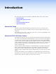
Introduction This section gives an overview of the DVS 510 and DVS 510 SA scalers. Topics include: • About this Guide • About the DVS 510 Series Scalers • Features • Controlling the DVS 510 Series • Application Diagram About this Guide This guide contains information about the Extron DVS 510 Series of switching scalers with instructions for experienced installers on how to install, configure, and operate the equipment.
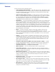
Features The DVS 510 provides the following features: • Video upscaling and downscaling — DVI, RGB computer video, high definition video, and standard definition video sources can all be scaled to the desired output resolution. The DVS 510 scaling engine provides high quality upscaling and downscaling of high resolution computer video signals.
• PIP (picture-in-picture) — Allows a video source to be displayed within a high resolution image, or vice versa. Audio switching can be set to follow either the main or PIP window. • Glitch-free switching — Switching between sources occurs without distortions or glitches with selectable cut or fade-to-black transitions. • Customizable front panel control buttons — The tri-colored, backlit pushbuttons on the front panel can be custom-labeled.
• Test patterns — 12 test patterns are provided for calibration and setup, including a crop pattern, crosshatch, 16 bar grayscale, color bars, alternating pixels, ramp, white field, 4 x 4 crosshatch, and four aspect ratio patterns (1.33, 1.78, 1.85, and 2.35). • Front panel security lockout (executive mode) — When enabled, locks out all front panel functions except for input selection (all functions remain available through RS-232, RS-422, or IR remote control).
Application Diagram The following diagram shows an example of a DVS 510 SA application.
Installation This section gives an overview of the steps to installing the DVS 510. It also provides a description of the rear panel connectors and instructions for cabling. The following topics are discussed: • Installation Overview • Rear Panel • Connecting to the RS-232 Config Port (Front Panel) • Wiring the Amplified Audio Ports (DVS 510 SA Only) Installation Overview Follow these steps to install and set up the DVS 510: 1.
5. Connect power to the DVS by plugging a standard IEC power cord (provided) from a 100 to 240 VAC, 50-60 Hz AC power source into the power receptacle (a). 6. Configure the DVS 510 using the SPPCP (see the control program help file), SIS commands (see the “Remote Configuration and Control” section, beginning on page 47), the web pages (see the “HTML Configuration and Control” section, beginning on page 85), or any combination of these methods.
e Video inputs 7/8 and 9/10 — Connect two DVI, two RGB/YUV, or one each video sources to these DVI-I connectors. The analog portions of these connectors are identified as inputs 7 and 9, while the DVI portions are recognized as inputs 8 and 10. These connectors feature EDID emulation. The following tables show the DVI-I connector pin assignments for DVI and analog source connection.
f RGB/YUV output connectors — Connect cables from RGB (RGBHV, RGBS, RGsB) or YUVp/HD component (R-Y, Y, B-Y) display devices to these female 15-pin HD connectors for scaled RGB or component video output. The output can be scaled to 69 different output rates (see the resolution and refresh rates table on page 27). NOTE: g h Outputs are buffered and can be connected simultaneously to two different displays. The sync and video formats are the same for all outputs.
j Variable audio output connector — Connect an audio device to this female 5-pole 3.5 mm captive screw connector for balanced or unbalanced variable audio output. This output is affected by tone control, gain, attenuation, and audio delay. Wire the connector as shown below. No Ground Here L L R Tip Sleeves Tip Do not tin the wires! R Tip Ring Sleeves Tip Ring No Ground Here Balanced Audio Output Figure 5.
o RS232 connector — This female 9-pin DB-9 connector provides for RS-232 or RS-422 remote communication. Connect a host computer or control system to this connector for serial control of the DVS by Simple Instruction Set (SIS) commands (see the “Remote Configuration and Control” section, beginning on page 47) or by the SPPCP software (see the control program help file). The default protocol for this port is 9600 baud, 1 stop bit, no parity, and no flow control.
Wiring the Amplified Audio Port (DVS 510 SA Only) To connect speakers to the DVS 510 SA built-in amplifier, terminate the speaker cable as follows: 1. Strip the end of the cable 3/16 inches (5 mm). CAUTIONS: • The length of the exposed wires in the stripping process is critical. The ideal length is 3/16 inches (5 mm). If the exposed portion is longer, the wires may touch, causing a short circuit between them.
Fig 10 Connection examples AMPLIFIED OUTPUTS AMPLIFIED OUTPUTS 8 Ohms Stereo L+ L 8 Ohms Stereo R+ Mono + Stereo R– Mono – R Stereo L– Mono + L 8 Ohm Load Mono – 8 Ohm Load Dual Mono Connection Stereo Connection AMPLIFIED OUTPUTS 4/8 Ohms Mono + or Stereo L+ 4 Ohm Total Load Figure 10. Mono – or Stereo L- Two 8 ohm speakers wired in parallel equal a 4 ohm load.
Operation This section discusses the functions available through the front panel to set up and operate the DVS 510 or DVS 510 SA.
a Input Buttons — Press the desired input button to select an input and switch it to the current output. The visual effect accompanying the switch (switch effect) can be a cut or a fade, depending on the selection (see “Advanced Configuration Menu” on page 29). With front panel input selection, audio always follows (switches with) the front panel video selection.
c Picture control buttons — Press these buttons to adjust window and image size, position, brightness, range of dark and light values (contrast), color, tint, detail, zoom (magnify or reduce), and pan. When one of these buttons is pressed, it lights amber. NOTE: When PIP mode is enabled, all picture control adjustments affect only the PIP window. (See “Picture Controls” on page 36 for details on these button functions.
Powering On Apply power to the DVS by connecting the provided IEC power cord from the rear panel power connector to an AC power source. The scaler performs a self-test during which all the front panel buttons blink red, then green, then amber. At the same time, the initial two power-up screens are displayed on the LCD screen.
Picture-in-Picture (PIP) Mode The picture-in-picture (PIP) feature lets the DVS display two image sources on the screen simultaneously. One of these image sources must be low-resolution (composite, S-video, YUVi, or RGBcvS) video, while the other must be high resolution (YUVp/HDTV, RGB, or DVI) video. • High resolution — Inputs 5 through 7 and 9 if they are configured as RGB (RGBHV, RGBS or RGsB) or high-resolution component video YUVp/HDTV; inputs 8 and 10 (DVI).
Enabling PIP Mode To enable picture-in-picture mode: 1. Select an input for the main window. The selected input button lights amber. 2. Configure the input for the main window as desired (see “Input Configuration Menu” on page 23 and “Picture Controls” on page 36). 3. Press the PIP On/Off button to activate the PIP mode. • The input button for the PIP window lights green.
Menus on the LCD Screen The DVS 510 menus that are displayed on the LCD screen enable you to configure and operate the scaler. The menu navigation buttons (Menu and Next) are located to the right of the LCD screen. Press these buttons to cycle through the available menus and submenus, and use the horizontal and vertical Adjust knobs to select options. This section describes the options on these menus and their submenus, including any procedures that are initiated from them.
Menu flow diagram The flow diagram below shows the menus that are displayed in the front panel LCD window and the order in which they appear when you repeatedly press the Menu button. Power On Initializing Please Wait... 2 sec. Extron DVS 510 V1.00 2 sec. Default Cycle Menu User Presets 30 sec. Menu Input Configuration 30 sec. Menu Output Configuration 30 sec. Menu Audio Configuration 30 sec. Menu Advanced Configuration 30 sec. Menu View Comm Setting 30 sec.
User Presets Menu User presets save the current set of image parameters for the selected input. Each input has 16 available user memory presets to which you can save settings or recall using this menu, an SIS command (see the User presets commands in the Command and Response Table for SIS Commands on page 62) or the Presets web page (see “Memory/Input Presets Page” on page 102).
Input Configuration Menu The Input Configuration menu allows you to select a video signal type for the configurable inputs: 5, 6, 7, and 9. (Inputs 1 and 2 are composite video only, inputs 3 and 4 are S-video only, and inputs 8 and 10 are DVI only.) The table below summarizes the available signal types for each input.
Selecting an input To select an input, press the numbered input button. The button lights amber. The selected input number is displayed in the LCD window on the first screen of the default cycle. Inputs can also be selected via an SIS command, the SPPCP software, the web pages, and the IR 904 remote control. In #5 RGB 47.8kHz 60.0Hz Configuring an input Follow these steps to configure any of the 10 video inputs: 1. Press the numbered button for the input to configure. 2.
Input Configuration Submenu Horizontal ([) and Vertical Knob ({) Adjustment Video Signal Type (Inputs 5, 6, 7, and 9) Select the desired video format for the selected input (this adjustment is available only for inputs 5, 6, 7, and 9). The default is RGB. Accepted video signal types include RGB, RGBcvS, YUVp/HDTV, and YUVi. Film Mode Detect Enable and disable 3:2 pulldown detection for NTSC and 2:2 film detection for PAL video sources.
Output Configuration Menu The output configuration menu allows you to set output resolution and refresh rate, output signal type, and sync polarity (RGBHV only). The following flow diagram shows the output configuration submenus and the adjustments that can be made from them. Input Configuration Menu Output Configuration Next Resol 1024 x 768 Refresh @ 60 Hz Resolution Refresh Rate Select the output resolution and refresh rate.
Resolution 23.98 Hz 24 Hz 25 Hz 29.97 Hz 30 Hz 50 Hz 59.
Audio Configuration Menu The Audio Configuration menu enables you to adjust the levels of gain, attenuation, bass, and treble; enable and disable the limiter for the amplifier (DVS 510 SA only); turn audio delay on and off; and select the audio output type (stereo or dual mono). The flow diagram below shows the Audio Configuration submenus and the adjustments that can be made from them.
Audio Delay submenu This submenu lets you delay the audio to match the video delay. To enable audio delay, rotate either Adjust knob to the right until the LCD screen displays On. To disable audio delay, rotate either knob to the left until Off is displayed. The default is On. Audio Output submenu From this submenu you can select stereo or dual mono for the audio output type.
Auto Image submenu Auto-Image is enabled per input. When an input is connected and Auto-Image is enabled, the DVS performs an image adjustment in which it measures where the active area starts and stops, then adjusts input sampling accordingly, so that the image fills the window. The scaler measures the sync frequencies of the incoming video source and sets the active image area, total image area, and the sampling frequency according to a table stored on the DVS.
Auto Memories and Auto-Image Interaction Auto memories Auto-Image Action On On New signals or rates that have not been previously detected by the DVS 510 are initially set up using default parameters, then Auto-Image is applied and the values are stored. The next time that signal is detected, the values stored in the auto memory location are applied. On Off (Default) New signals or rates that have not been previously detected by the DVS 510 are set up using default parameters.
Switch Effect submenu Two effects are available to be displayed on the output screen when the input is switched: • Cut — The current input is immediately replaced with the image from the new input. • Fade — The current input fades to black and the new input fades in (default). To select a switch effect: 1. From the Advanced Configuration menu, press Next until the Switch Effect submenu is displayed. 2. Rotate either Adjust knob to the right to select Fade or to the left to select Cut.
Color Bars Crop Crosshatch 1.33 Aspect 4x4 Crosshatch 1.78 Aspect Grayscale 1.85 Aspect Ramp 2.35 Aspect Alt Pixels Blue Mode White Field Figure 19. DVS 510 Series Test Patterns To select a test pattern: 1. From the Advanced Configuration menu, press Next until the Test Pattern submenu is displayed. 2. Rotate either Adjust knob to select a test pattern. The default is Off (no test pattern). Internal Temp. screen The Internal Temp.
View Comm Settings Menu The View Comm Settings menu lets you view the current settings for the communication ports, including the IP, subnet mask, and gateway addresses of the unit, the MAC (Media Access Code or hardware) address, the Dynamic Host Configuration Protocol (DHCP) status, and the serial port baud rate and type. NOTE: None of the settings can be changed from this menu; to make adjustments, use the Edit Comm Settings menu (see “Edit Comm Settings Menu”).
The flow diagram below shows the Edit Comm Settings screens and the adjustments that are available from them. Press and hold Next + [Detail+Color/Tint]. 2 Sec. Edit Comm Settings Next Serial Config 9600 RS232 Next Select the baud rate: 9600 (Default) 19200 38400 115200 • • • • Set DHCP Mode Off Next Select the serial communication type: • RS232 • RS422 Set the DHCP mode: Off (Default) On • • Set Gateway Addr 000.000.000.000 Set the Gateway Address: Select an octet.
Set IP Address submenu Valid IP addresses consist of four 1-, 2-, or 3-digit numeric sub-fields (called “octets”) that are separated by periods. Each octet can be numbered from 000 through 255 (leading zeros are inserted by the DVS). The factory-installed default address is 192.168.254.254, but if this conflicts with other equipment at your installation, you can change the IP address to any valid value via the Set IP Address screen. To change the unit IP address: 1.
Adjusting the Picture Controls To adjust the picture controls for the currently selected input: 1. Press the button for the input that you want to adjust. If you want to adjust the PIP window, press the PIP On/Off button to enter PIP mode, then press the button for the PIP input. 2. Press the desired picture control button: Size, Bright/Cont (brightness and contrast), Detail (sharpness), Position (centering), Color/Tint (color quality), or Zoom/Pan (magnification or horizontal and vertical panning). 3.
Input Presets The DVS 510 Series has 128 input preset slots, which can save signal type, input configuration settings, and picture control settings for any of the inputs. These presets can be saved and recalled using the Windows-based control software (see the Signal Processing Products Control Program help file), SIS commands (see the Input Presets commands on page 63 in the Command and Response Table for SIS Commands) or the DVS 510 Series web pages (see “Memory/Input Presets Page” on page 102).
Volume Control Rotating the Volume knob on the front panel increases and decreases the audio volume in up to 100 steps. NOTE: This knob is speed sensitive; that is, you can turn the knob quickly to make coarse adjustments or slowly to make fine adjustments. The table below shows some examples of the amount of rotation needed to achieve volume levels.
VOLUME VOLUME MAX MAX MID MID MID MIN MIN MIN MIN LED flashes when volume level is at 0% or audio muted. VOLUME MIN LED on solid when volume level is at 1% or higher. MID LED on solid when volume level is at 50% or higher. VOLUME MAX MAX MID MID MIN MIN MAX LED on solid when volume level is at 80% or higher. Figure 23. VOLUME MAX MAX LED flashes when volume level is at 100% (maximum).
DVS 510 Series Reset Mode Summary Run and Stop Events Factory Firmware Mode Activation Result Purpose and Notes Use mode 1 to revert to the factory default version for a single power cycle if incompatibility issues arise with user-loaded firmware. 1 Hold in the recessed Reset button while applying power to the unit. The DVS reverts to the factory default firmware for a single power cycle. Event scripting does not start if the unit is powered on in this mode.
Front Panel Lockout (Executive Mode) To prevent accidental changes to settings, you can lock the DVS 510 front panel controls by placing the scaler in lock (executive) mode 1 or 2. While the DVS is in lock mode, RS-232, RS-422, and Ethernet communication, as well as IR remote control, remain available. • Lock mode 1 locks all front panel functions.
Output Sync Mute This function mutes all video and sync outputs, placing the display device in a power save mode. Output sync mute is available only via SIS commands (see the Video Mute commands on page 57, in the Command and Response Table for SIS Commands). NOTE: Individual outputs cannot be muted by this command. With the output sync mute enabled, all analog and digital outputs are simultaneously disabled. Overscan Mode This function allows you to set a default overscan of 0%, 2.
Locking IR Remote Control Access The DVS can be set to lock out users from using the IR 904 Remote Control to control the scaler. Remote access can be enabled and disabled via SIS commands (see the IR Receiver commands on page 65 in the Command and Response Table for SIS Commands). When remote access is locked, all other controls remain available (SIS commands, web pages, control software, and front panel). NOTES: • By default, the IR receiver is disabled.
a PIP control buttons — Control the picture-in-picture (PIP) function: • PIP On/Off button — Toggles between showing and hiding the picture-in-picture on the display (enabling and disabling PIP mode). • PIP Swap button — Toggles the primary (main or background) and secondary (PIP) pictures between the main image and the PIP window. b Volume — Press the top (up arrow) or bottom (down arrow) of this rocker button to raise or lower the output volume level.
f Image Adjustment buttons — Let you make adjustments to the appearance of the image on the screen, including color, tint, contrast, brightness, and sharpness (Detail). For each of these controls, there are two buttons: + to increase the image property and – to decrease it. You can also freeze the image on the screen (the Freeze button has no equivalent on the front panel). To adjust the image using the remote control buttons: 1. Aim the IR 904 remote control at the front panel IR sensor. 2.
Remote Configuration and Control The DVS 510 can be remotely controlled via a host computer or other device (such as a control system) attached to the rear panel RS232 connector, the front panel RS-232 Config port, or the LAN port.
IP Address To access the DVS 510 or DVS 510 SA via the Ethernet port, obtain the IP address of the scaler from your network administrator. If the IP address has been changed to an address comprised of words and characters, you can determine the actual numeric IP address using the ping (ICMP) utility (see “IP Addressing” on page 116 for more details). If the IP address has not been changed, the factory-specified default is 192.168.254.254.
Scaler-initiated Messages When a local event such as a front panel input selection or adjustment takes place, the DVS responds by sending a message to the host. No response is required from the host. Some scaler-initiated messages are listed here. • (c) Copyright 20nn, Extron Electronics, DVS 510, Vn.nn., 60-835-0n ] Www, DD Mmm YYYY hh:mm:ss ] The DVS sends the copyright message upon connecting to the computer via IP, or when powering up while connected. Vn.nn is the firmware version number.
Error Response References 14 = Commands that give an E14 (invalid command for this configuration) error if sent to a product whose current configuration does not support the command 24 = Commands that give an E24 (privilege violation) error if you are not logged on at administrator level 27 = Commands that may give an E27 (invalid event number) error 28 = Commands that may give an E28 (file not found) error Using the Command and Response Tables These tables contain Telnet (port 23), serial, or web b
Space ASCII to Hex Conversion Table • Figure 28. NOTE: ASCII to Hexadecimal Character Conversion Table Upper- and lowercase text can be used interchangeably except where noted. Symbol Definitions for DVS 510 Series SIS Commands • = Space Carriage return with line feed Carriage return with no line feed | = Pipe (vertical bar) character. For URL-encoded commands, has the same function as }.
X1$ = Input preset name X1% X1^ X1& X1* X1( Picture adjustment H and V position H and V size Zoom Pan (value depends on the zoom setting) Test pattern = = = = = X2) = 16 characters maximum; ASCII characters 23 through 126 only 0 through 127 Value based on the current output resolution Value based on the current output resolution 100% through 200% 0 = None 7 = White Field 1 = Color Bars 8 = Crop 2 = Crosshatch 9 = 1.33 Aspect Ratio 3 = 4x4 Crosshatch 10 = 1.
X2# = Output polarity 0 = H- / V- (default) 1 = H- / V+ 2 = H+ / V3 = H+/ V+ 0 = RGBHV (default) 3 = YUV bi-level 1 = RGBS 4 = YUV tri-level 2 = RGsB 1 through 16 The following parameters are saved in user presets: X2$ = Output sync format X2% = User presets • Color • Detail • Vertical size • Tint • Horizontal position • Pan • Contrast • Vertical position • Zoom • Brightness • Horizontal size X2^ = Input presets 1 through 128 The following parameters are saved in input presets: • Input
X4% = Video switching effect X5) = X5! = X5@ X5# X5$ X5% = = = = X5& = X5* = X5( = 0 = Cut: instantly switches video. 1 = Fade: video fades to black, then fades to the new input. Audio volume Range of 0 through 100 Audio output format 1 = Mono 2 = Stereo (default) Audio gain level 0 through 12 dB (decibels above zero) Audio attenuation level 12 through 0 dB (decibels below zero) Audio gain or attenuation level Unit response; can be positive or negative.
Command and Response Table for DVS 510 Series SIS Commands ASCII Command (Host to Scaler) Response (Scaler to Host) Video and audio X! ! In X! • All ] Select video and audio from input source X!. Video X! & In X! • RGB ] Select video from input source X!. Audio X! $ In X! • Aud ] Select audio from input source X!. Command Additional Description Input Selection NOTES: • When the DVS is in PIP mode, the input selection command affects the PIP window.
ASCII Command (Host to Scaler) Response (Scaler to Host) Specify a value E X$ HSRT } Hsrt X! * X$ ] Set the horizontal location of the first active pixel in the active window to X$. Increment value E + HSRT } Hsrt X! * X$ ] Increment the horizontal start position. Decrement value E – HSRT } Hsrt X! * X$ ] Decrement the horizontal start position. View horizontal start E HSRT } X$ ] Show the horizontal location of the first active pixel in the active window.
ASCII Command (Host to Scaler) Response (Scaler to Host) Specify a value E X( ALIN } Alin X! * X( ] Adjust the active lines value to X(. Increment value E + ALIN } Alin X! * X( ] Increase the number of active lines. Decrement value E – ALIN } Alin X! * X( ] Decrease the number of active lines. View active lines E ALIN } X( ] Show the number of active lines.
Command ASCII Command (Host to Scaler) Response (Scaler to Host) Additional Description Picture Controls (continued) Contrast Specific value E X1% CONT } Cont X! * X1% ] Set the contrast level to X1%. Increment up E + CONT } Cont X! * X1% ] Select the next higher contrast level. Increment down E – CONT } Cont X! * X1% ] Select the next lower contrast level. View contrast setting E CONT } X1% ] View the current contrast setting.
Command ASCII Command (Host to Scaler) Response (Scaler to Host) Additional Description Vertical Size NOTE: The vertical size range (X1&) is based on the current output resolution. Specific value E X1& VSIZ } Vsiz X! * X1& ] Set the window height to X1&. Increase size E + VSIZ } Vsiz X! * X1& ] Make the window taller. Decrease size E – VSIZ } Vsiz X! * X1& ] Make the window shorter. View E VSIZ } X1& ] View vertical sizing (height) value X1&.
ASCII Command (Host to Scaler) Command Response (Scaler to Host) Additional Description Output Sync Format and Polarity E X2$ OSYN } Set sync format Osyn X2$ ] Set the sync format for the VGA output to X2$. NOTE: Setting the sync format to YUV bi-level and tri-level also affects the colorspace of the DVI output. View sync format E OSYN } X2$ ] View the current output sync format. Set polarity E X2# OPOL } Opol X2# ] Set the sync polarity for the VGA output to X2#.
Command ASCII Command (Host to Scaler) Response (Scaler to Host) Additional Description Picture-in-Picture (PIP) (continued) View PIP input E PIP } X! ] View the input in the PIP window. Swap % Tke ] Exchange the displayed content between the main and PIP windows. Set output volume X5) V Vol X5) ] Set the volume for the output to X5). Increment volume +V Vol X5) ] Increase the audio volume. Decrement volume –V Vol X5) ] Decrease the audio volume.
Command ASCII Command (Host to Scaler) Response (Scaler to Host) Additional Description Audio Commands (continued) Limit Audio Level on Power-up Set power-up limit E X5) ALMT } View setting E ALMT } Almt X5) ] X5) ] Set the maximum volume level at power-up to X5). Show the current power-up volume limit. Audio Input Format (for embedded digital audio source) Set digital 2-channel audio E I 2 AFMT } Afmt I 2 ] Select digital 2-channel audio EDID (default).
ASCII Command (Host to Scaler) Response (Scaler to Host) Recall input preset 2 * X2^ . 2 Rpr X2^ ] Recall input preset X2^. Save input preset 2 * X2^ , 2 Spr X2^ ] Save the parameters of the current input to preset X2^ (for saved parameters, see “Input presets” under “Symbol Definitions for DVS 510 Series SIS Commands”). E X2^ , X1$ NP } Nmp X2^ , X1$ ] Set name of preset X2^ to X1$. The command character is a comma. Presets can have up to 16 characters.
Command ASCII Command (Host to Scaler) Response (Scaler to Host) Additional Description Advanced Configuration (continued) Front Panel Security Lockout (Executive Mode) Set mode 1 1X Exe 1 ] Lock all front panel functions. Set mode 2 2X Exe 2 ] Allow limited adjustments to be made from the front panel (input switching, PIP, volume control, and Auto-Image). Disable 0X Exe 0 ] Allow all front panel adjustments. View status X X5( ] Show current lock mode status.
Command ASCII Command (Host to Scaler) Response (Scaler to Host) Additional Description Advanced Configuration (continued) HDCP Signal Status Query input E I HDCP } X4$ ] Request the HDCP signal status of the current input. Query output E O HDCP } X4$ ] Request the HDCP signal status of the DVI output. Video Switch Effect NOTE: The video switch effect also affects the audio switch, as discussed in the following command descriptions. E 0 SWEF } Swef 0 ] Set the video switch effect to cut.
ASCII Command (Host to Scaler) Response (Scaler to Host) Erase flash memory24 E ZFFF } Zpf ] Clear all data from flash memory. Reset audio settings E ZA } Zpa ] Reset the audio input gain and global treble and bass settings to 0. Reset all audio settings E ZAAA } Zaa ] Reset all audio settings to the factory defaults. Reset all settings to factory defaults E ZXXX } Zpx ] Reset all settings and adjustments to the factory default settings.
Symbol Definitions for IP-specific SIS Commands • = ] = } = | = E = W = Space Carriage return with line feed Carriage return with no line feed Pipe (vertical bar) character. For URL-encoded commands, has the same function as ]. Escape For URL-encoded commands, has the same function as E 14, 24, 27, 28 = Superscripts indicate the error message displayed if the command is entered incorrectly or with invalid parameters (see “Error Response References” on page 50).
X8* = Time (in 10-ms increments) to wait 2 through 32767 between characters before Default = 2, or 20 ms terminating the connection X8( = Hardware (MAC) address 00-05-A6-xx-xx-xx X9) = Subnet mask nnn.nnn.nnn.nnn (Leading zeros in each of the four fields are optional for setting values and are suppressed in returned values. Factory default subnet mask: 255.255.0.0 X9! = Message length, delimiter value, nL = Length of message to be received.
X10% = Event buffer X10^ = X10& = Event buffer offset Event data size NOTE: X10* = X10( = 0 = receive 1 = unified 2 = data 3 = NVRAM 0 through maximum buffer size b = bit B = byte (8 bits) S = short (16 bits) L = long (32 bits) In a write operation, this parameter can optionally be preceded by A (for and) or O (for or) to logically combine with content instead of replacing it.
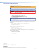
Command and Response Table for IP-Specific SIS Commands ASCII Command Command (Host to Scaler) Response (Scaler to Host) Additional Description Bidirectional Serial Port E X7! * X8& * X8* * X9! RS } X7@ Send data string Configure port type Configure port parameters24 response from command ] E X! * X7! CY } Cpn X! • Cty X7! ] For X7!: 0 = RS-232; 1 = RS-422 E X7! * X9%,X9^,X9&,X9* CP } Cpn X7! • X9%,X9^,X9&,X9* ] Set baud rate X9%, parity X9^, X9& data bits, and X9* stop bits for port X7!.
ASCII Command Response Set current connection port timeout E 0 * X12( TC } Pti0 * X12( ] View current connection port timeout Set global port timeout View global port timeout E 0 TC } X12( ] E 1* X12( TC } E 1TC } Pti1* X12( ] Set unit name E X8@ CN } Ipn • X8@ ] View unit name Reset unit name to factory default24 E CN } E • CN } X8@ ] Ipn • X11% ] Command (Host to Scaler) (Scaler to Host) Additional Description Ethernet Data Port Set number of seconds (in tens of seconds) before timeout
Command ASCII Command (Host to Scaler) Response (Scaler to Host) Additional Description IP Setup Commands (continued) Set Daylight Saving Time24 E X10# CX } Ipx X10# ] View Daylight Saving Time Set DHCP on24 E CX } X10# ] E 1DH } Idh1 ] Set DHCP off24 View DHCP mode E 0DH } E DH } Idh0 ] Set IP address E X8$ CI } Ipi • X8$ ] View IP address E CI } X8$ ] View hardware (MAC) address E CH } X8( ] View number of open connections E CC } Set subnet mask E X9) CS} View subnet mask E C
ASCII Command Command (Host to Scaler) Response (Scaler to Host) Additional Description IP Setup Commands (continued) Set verbose mode E X9@ CV } Vrb X9@ ] Set verbose mode X9@. For X9@: 0 = verbose mode and tagged responses disabled 1 = verbose mode 2 = tagged responses for queries 3 = verbose mode and tagged responses for queries Default is 0 for Telnet connections and 1 for RS-232 or RS-422 control.
ASCII Command Command (Host to Scaler) Response (Scaler to Host) Additional Description Password and Security Settings (continued) Set user password14 E X10@ CU } Ipu • X10( ] Set user access password X10@. X10@ = 4 to 12 alphanumeric characters. The password is case sensitive. Special characters (spaces or symbols) are not allowed. X10( = password. If a password exists, the unit responds with the password (RS-232 or RS-422 connection) or 4 asterisks (****) (IP connection).
ASCII Command Command (Host to Scaler) Response (Scaler to Host) Additional Description Directories NOTES: • Directory name = a text string that can contain letters A–Z, a–z, digits 1–9, minus signs or hyphens (-), plus sign (+), or colon (:). No blank or space characters are permitted. Names are not case-sensitive. The first character must be an alpha character. • A directory does not truly exist until a file has been copied into that path. • A file and a directory can have the same name.
ASCII Command Command (Host to Scaler) Response (Scaler to Host) Additional Description Stream Files via Telnet, RS-232, or RS-422 Load file to user flash memory24,28 Load file to user flash and set specific time and date24,28 E +UF filesize, filename } Upl ] E +UF filesize*day-of-week•month•day•year•hour•minute•second, filename } Upl ] Day-of-week = 1–7 (1 = Sunday, 2 = Monday ...) Month = 1–12 (1 = Jan, 2 = Feb, ...
ASCII Command Command (Host to Scaler) Response (Scaler to Host) Additional Description Event Control View event buffer memory27 Write event buffer memory24,27 E X10$,X10%,X10^,X10& E } X12) ] E X10$,X10%,X10^,X10* X10& E } Evt X10$,X10%,X10^,X10* ] NOTE: The response to the Write Event command is padded with leading zeros for X10$ and X10^. X10$ = 5 digits; X10^ = 10 digits.
Using the Signal Processing Products Control Program (SPPCP) The Windows-based Extron Signal Processing Products Control Program (SPPCP) offers an alternative way to control the DVS 510 Series via an RS-232, RS-422, or Ethernet connection. The graphical user interface includes the same functions as those on the scaler front panel with additional features that are available only through the software. The control software is compatible with Windows 98, Windows NT, Windows 2000, Windows XP, and Windows 7.
4. Follow the on-screen instructions to complete the installation. By default, the installation creates a C:\Program Files\Extron\Signal Processing directory and places a shortcut icon in it. Installing from the Extron website If you do not have an Extron software DVD, you can download the SPPCP software free of charge from the web as follows: 1. On the Extron website (www.extron.com) opening screen, select the Download tab. 2.
Starting the Software 1. Click Start > Programs > Extron Electronics > Signal Processing > Signal Processing Products Control Program. Alternatively, if an SPPCP icon was installed on the desktop, double-click the icon. The Select Connection Type window appears. 2. Select either the TCP/IP tab for an IP connection or the RS232 tab for a serial connection. • For an IP connection: • In the IP Address/Host Name field, either enter the IP address of your DVS or select the address from the menu. NOTE: • 192.
Fig: SPPCP Main Window Figure 35. Signal Processing Products Control Program Main Window Accessing the Help File For instructions on using the SPPCP software, see the control program help file. To view this file, do either of the following: • Select Contents from the Help menu. • Press the key on your computer keyboard.
Updating the Firmware Using SPPCP The Firmware Loader utility, accessed through the Signal Processing Products Control Program, provides a way to replace the DVS 510 firmware. In addition to being provided on the Extron Software DVD, the Firmware Loader is available free of charge from the Extron website. To update the firmware using the Firmware Loader: 1. If necessary, download the Firmware Loader software from the Extron website (www.extron.com): a. On the Extron web page, select the Download tab. b.
6. Double-click on in the New Firmware File column, or select New Firmware for Selected Devices from the File menu. Figure 36. Firmware Loader Window The Choose Firmware File window opens. Figure 37. Choose Firmware File Window 7. Navigate to the new firmware file, which has a .s19 extension, and double-click it. The Choose Firmware File window closes. CAUTION: Valid firmware files must have the file extension .s19.
8. Click Begin. The following indicators on the Firmware Loader window show the progress of the update: • The Transfer Time field shows the amounts of remaining and elapsed time for the update. • The Total Progress field displays a status bar with Uploading... above it. • In the Devices section, the Progress column displays an incrementing percentage and the Status column displays Uploading. Figure 38. Firmware Upload in Progress When the upload is complete, the Remaining Time field shows 00.00.
HTML Configuration and Control This section provides procedures for accessing and using the DVS 510 embedded web pages. The following topics are included: • Accessing the Web Pages • Special Characters • System Status Page • Configuration Pages • File Management Page • Control Pages The DVS can be controlled and operated through its Ethernet port, connected via a LAN or WAN and using a web browser such as Microsoft® Internet Explorer®.
4. Press the key. The DVS checks to see if it is password protected. • If the scaler is not password protected, the System Status web page opens. • If the DVS is password protected, the network password dialog box is displayed. Figure 39. Example of a Network Password Dialog Box 5. If an administrator or user password is required, enter it in the Password field. If desired, select the check box to have the system input your password the next time you enter your DVS IP address. Click OK.
System Status Page The System Status page provides an overall view of the status of the DVS, including firmware version and serial port settings. The System Status page is the default page that the scaler downloads when connected. You can access the System Status page from other pages by clicking the Status tab. Figure 40. System Status Page The System Status web page updates itself periodically to reflect the latest status of the scaler.
Configuration Pages The Configuration tab contains four pages that only an administrator can access. These pages are listed in the left sidebar menu on the Configuration tab. The following sections describe the changes you can make from these pages. System Settings Page The DVS 510 displays the System Settings page when you click the Configuration tab. The screen consists of fields in which you can view and edit IP administration and system settings.
IP Settings Fields The IP Settings fields let you view and edit settings unique to the Ethernet interface. After editing any of the IP settings, click the Submit button at the bottom of this section. Unit Name field The Unit Name field contains the name used as the “from” information when the DVS e-mails notification of its failed or repaired status. You can change this name field to any valid name, up to 24 alphanumeric characters.
Date/Time Settings section The fields in the Date/Time Settings section enable you to view and set the date and time parameters. Figure 42. Date/Time Settings Fields To change the date and time settings: 1. In each Date or Time field that you want to change, select the desired value from the drop-down menu or key it in the field. (The Month drop-down box is selected in the figure above); or Click the Local Date/Time button to set the date and time to your local settings. 2.
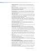
Scaler Settings page The Scaler Settings page simulates elements of the DVS 510 front panel menu system and also allows you to set video input signals (for inputs 5, 6, 7, and 9 only), configure the output, and remotely select advanced configuration options. Figure 43. Scaler Settings Page Input Configuration section The Input Configuration section contains drop-down menus that enable you to select various parameters for all or some of the inputs.
• EDID: Select an EDID (resolution and refresh rate) for inputs 5, 6, 8, and 10. You can select Match Output, which applies the EDID of the output to the selected input, or select one of the following EDIDs: 640x480 @ 50 Hz 1024x1024 @ 60 Hz 1360x768 @ 75 Hz 1680x1050 @ 60 Hz 1080i @ 60 Hz 640x480 @ 60 Hz 1024x1024 @ 75 Hz 1365x768 @ 50 Hz 1600x1200 @ 50 Hz 1080p @ 23.
Fig_Test Patterns Color Bars Crop Crosshatch 1.33 Aspect 4x4 Crosshatch 1.78 Aspect Grayscale 1.85 Aspect Ramp 2.35 Aspect Alt Pixels Blue Mode White Field Figure 44. Test Patterns on the DVS 510 The default is Off (no test pattern). (See “Test Pattern submenu” on page 32 for more information on using test patterns.) • Auto Memories: Select On or Off to enable or disable auto memories.
Passwords Page Access the Passwords page by clicking the Passwords link on the sidebar menu on the System Settings page. Figure 45. Passwords Page Setting a password The fields on the Passwords page are used to enter and verify administrator and user passwords. Passwords are case-sensitive and are limited to 12 upper- and lowercase alphanumeric characters. 1. Enter the new administrator password in the Administrator Password field. 2.
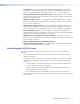
Firmware Upgrade page The Firmware Upgrade page lets you update the firmware that is loaded on the DVS control board without taking the scaler out of service. Access the Firmware Upgrade page by clicking the Firmware Upgrade link on the System Settings page. Figure 46. Firmware Upgrade Page To update firmware using the Firmware Upgrade page: 1. From the Extron website, download the latest firmware file and install it on your computer. a. On the Extron web page, select the Download tab. b.
5. Click the Browse button. A Choose File to Upload window opens. Figure 47. Choose File to Upload Window with a Firmware File Selected 6. Navigate to the folder where you saved the firmware upgrade file and double-click on the firmware file name (it must have a .s19 extension). The Choose Firmware File window closes, and the path to the new firmware file is displayed in the “Current Firmware Version n.nn” field on the Firmware Upgrade page. CAUTION: Valid firmware files must have the file extension .S19.
File Management Page The File Management page is a useful tool that allows you to use and upload existing and custom web pages. Custom pages can be developed using a third-party web page development program such as Microsoft Office FrontPage or Adobe® Dreamweaver®. File management also allows you to remove unnecessary or outdated files when they are no longer needed. To access this page, click the File Management tab. Figure 48.
Adding a Directory To add a directory or folder to the DVS file system: 1. Enter the directory name in the Dir: field, following the slash (/). 2. Click the Add Dir button. 3. With the directory name displayed, perform the uploading files procedure described on the previous page to add a file to the directory. The directory name appears at the top of the Files column, preceded by a slash (/). To add more files to the directory, click the directory name to open it, then perform the uploading files procedure.
User Control Page The User Control page simulates elements of the DVS 510 front panel and also includes other features such as picture control, mute and freeze options, Auto-Image, film mode detection, aspect ratio selection, and front panel lockout (executive mode). Figure 49. User Control Page On the User Control page, you can perform the following functions: Selecting an input and signal type Before selecting an input, you must select video, audio, or both for output. To select an input: 1.
2. In the Input Selection section, click the desired input button. The button on the screen is highlighted and its equivalent button on the front panel lights as follows, depending on your signal type selection: • If you selected Both as the signal type, the input button on the screen is highlighted and the equivalent front panel button lights amber.
Picture Control From the User Control screen, you can adjust the picture controls listed below. NOTE: These controls are not available when the DVS is in PIP mode. To adjust picture controls for the PIP window, click PIP Setup on the left sidebar menu to use the PIP Setup screen. To adjust the picture controls in this section (except for Pan), either click the + or – button to increase or decrease the value in the text field, or key in a value.
• Pixel Phase (RGB and YUVp/HDTV inputs only): Adjust the point at which pixels are sampled for the selected input. The range is 1 through 31; the default is 16. • Total Pixels (RGB and YUVp/HDTV inputs only): Increase or decrease the width in pixels of the total line of video. The default is the auto-sensed value. The range is ±512 from the auto-sensed value. • Active Pixels: Increase or decrease the width in pixels of the active video area of the selected input. The default is the auto-sensed value.
4. Click the Presets link on the left sidebar menu to display the Presets page. 5. From the Memory Presets drop-down menu, select a number for the preset you are creating. 6. Click the Save button. To recall a saved user preset: 1. From the Memory Presets drop-down menu, select a preset number. 2. Click the Recall button. The preset is applied to the current input.
PIP Setup Page Use the PIP Setup page to configure the picture-in-picture window. Figure 51. PIP Setup Page On this screen, you can specify the parameters described on the next page for the PIP window.
Selecting a PIP input The PIP input must be a different resolution type (high or low) from the main input. For example, if input 1 (composite video) is your main input, the PIP input can be selected from inputs 5 through 10 (high-resolution only).
Picture Control (PIP) In the Picture Control section, adjust the PIP controls as desired. Except for Pan, you can adjust these by either clicking the + or – button to increase or decrease the value in the text field, or by keying in a value. • Horizontal Shift: Move the image to the right or left on the display. The value in the text box is the distance in pixels of the left edge of the image from the left edge of the display.
Reference Information This section provides reference information on the DVS 510 Series.
Video output Number/signal type ������������������������ 2 scaled RGBHV, RGBS, RGsB; Y, R-Y, B-Y 1 scaled DVI/HDMI (HDCP compliant) Connectors ������������������������������������ 2 female 15-pin HD 1 female DVI-I (only digital signal active) Nominal level ��������������������������������� 1 Vp-p for Y of component video and for G of RGsB 0.7 Vp-p for RGB and for R-Y and B-Y of component video Minimum/maximum levels �������������� 0 V to 0.
Audio output Number/signal type ������������������������ Connectors ������������������������������������ Impedance ������������������������������������� Gain error �������������������������������������� Maximum level (Hi-Z) ���������������������� 1 stereo or 2 mono (2 channels total) (2) 3.5 mm captive screw connectors, 5-pole 50 ohms unbalanced, 100 ohms balanced ±0.
Mounting Rack mount ����������������������������� Yes, with included brackets Enclosure type �������������������������������� Metal Enclosure dimensions ��������������������� 3.5" H x 17.5" W x 9.4" D (2U high, full rack wide) (8.9 cm H x 44.4 cm W x 23.9 cm D) (Depth excludes connectors and knobs. Width excludes mounting brackets.) Product weight ������������������������������� 7.0 lbs (3.
Mounting the DVS 510 Scaler Rack Mounting UL guidelines for rack mounting The following Underwriters Laboratories (UL) guidelines pertain to the installation of the DVS 510 in a rack: • Elevated operating ambient temperature — If the equipment is installed in a closed or multi-unit rack assembly, the operating ambient temperature of the rack environment may be greater than room ambient.
Fig: Rack mounting MBD 249 2U Rack Mounting Bracket (Pre-attached) Figure 52. Rack Mounting a DVS 510 Scaler Tabletop Use To set up the unit for tabletop use: 1. Remove the eight screws to detach the mounting brackets from the sides of the unit. 2. Attach one of the provided self-adhesive rubber feet to each corner of the bottom of the unit. Button Labels The DVS 510 is delivered with button caps pre-labeled for your convenience.
3. Locate the small corner notch on the lens cap, and slide the screwdriver between the lens cap and the diffuser (see b in the illustration below). 4. Using a rotating motion of the screwdriver, carefully pry the two pieces apart (see c in the illustration below). 5. Lift out the transparent square label that you want to replace. You may need to use the small screwdriver to gently pry the label out. 6.
Figure 54. Button Label Generator Window (Example) 2. From the Systems pull-down menu, select a layout that most resembles the DVS 510 front panel buttons (although you can select any layout from this menu). You can also select Customize Button Layouts from the Tools menu to open the Customize button layout window, on which you can create your own layout. 3. Click on the button representation that you want to edit. A red box surrounds the selected button. 4.
Blank Button Labels DVS 510 Series • Reference Information 115
IP Addressing What is an IP Address? An IP address is a 32-bit binary number that is used to identify each device on an Ethernet network. This number is usually represented by four decimal numbers (each in the range of 0 to 255) separated by dots, such as 198.123.34.240. This is called “dotted decimal notation.” An IP address is divided into two parts: • Network identifier • Host identifier Each address on a given network must have the same network identifier value but a unique host identifier.
The following is an example of an invalid Class C addressing scheme: Device IP Address SPPCP Control Software Computer 208.132.180.41 DVS 510 192.157.180.42 NOTE: The above addresses are invalid because the network identifier for each address is not the same even though each IP address is unique. You can perform a test from your computer to check that a device at a particular address is responding correctly or to determine its address (see “Pinging for the IP Address”).
4. At the command prompt, enter ping IP address. The computer returns a display similar to figure 56. The line Pinging ... reports the actual numeric IP address, regardless of whether you entered the actual numeric IP address or an alias name. Figure 56. Ping Command and Response Pinging to determine the web IP address The Ping utility has a modifier, -a, that directs the command to return the web address rather than the numeric IP address. At the prompt, enter ping -a IP address.
4. At the prompt, enter telnet. The computer returns a display similar to the figure below. Figure 57. Telnet Screen Telnet tips It is not the intention of this guide to detail all of the operations and functionality of Telnet; however, some basic level of understanding is necessary for operating the DVS 510 Series via Telnet. Connecting to the DVS (Open command) Use the Open command to connect the computer to the DVS 510 scale.
Local echo Once your computer is connected to the DVS 510, by default Telnet does not display your keystrokes on the screen. SIS commands are entered blindly, and only the SIS responses are displayed on the screen. To command Telnet to show all keystrokes, enter set local_echo at the Telnet prompt before you open the connection to the scaler. With local echo turned on, keystrokes and the scaler responses are displayed on the same line.
Local and remote devices The local and remote devices are defined from the point of view of the function being described. In this guide, subnetting is an issue when you are using the controlling computer to set TCP/IP and e-mail values in the DVS (see “Establishing an Ethernet Connection Using TCP” on page 48. When you are setting up the variables for e-mail notification, the scaler is the local device and the e-mail server is the remote device.
Extron Warranty Extron Electronics warrants this product against defects in materials and workmanship for a period of three years from the date of purchase.