User Guide Matrix Switchers DXP DVI DXP DVI Pro DXP HDMI DVI, DVI Pro, and HDMI Series Digital Matrix Switchers 68-2192-01 Rev.
Safety Instructions • English Warning This symbol is intended to alert the user of important operating and maintenance (servicing) instructions in the literature provided with the equipment. Power sources • This equipment should be operated only from the power source indicated on the product. This equipment is intended to be used with a main power system with a grounded (neutral) conductor. The third (grounding) pin is a safety feature, do not attempt to bypass or disable it.
FCC Class A Notice This equipment has been tested and found to comply with the limits for a Class A digital device, pursuant to part 15 of the FCC rules. The Class A limits provide reasonable protection against harmful interference when the equipment is operated in a commercial environment. This equipment generates, uses, and can radiate radio frequency energy and, if not installed and used in accordance with the instruction manual, may cause harmful interference to radio communications.
Conventions Used in this Guide Notifications the following are used: WARNING: Risk of severe bodily injury. A warning indicates a situation that has the potential to result in death or severe injury. ATTENTION: Potential Damage to Property. Attention indicates a situation that may damage or destroy the product or associated equipment. NOTE: A note draws attention to important information. TIP: A tip provides a suggestion to make working with the application easier.
Contents Introduction............................................................ 1 About this Guide.................................................. 1 About the DXP DVI, DXP DVI Pro, and DXP HDMI Series Digital Matrix Switchers.......... 1 Features.............................................................. 2 DXP DVI and DXP DVI Pro Series.................... 2 DXP HDMI Series............................................ 2 DXP DVI, DXP DVI Pro, and DXP HDMI........... 2 Application Diagrams..............
Switcher Error Responses................................. 53 Using the Command and Response Tables for SIS Commands........................................... 53 Special Characters........................................ 53 SIS Commands for DXP.................................... 54 Symbol Definitions for DXP............................ 54 Command and Response Table for DXP SIS Commands.................................... 57 IP-specific SIS Commands................................
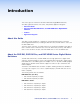
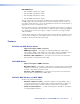
Introduction This section gives an overview of the Extron DXP Series Digital Matrix Switchers, describes significant features of the series, and provides application diagrams.
DXP HDMI Series: • DXP 44 HDMI: 4 inputs by 4 outputs • DXP 48 HDMI: 4 inputs by 8 outputs • DXP 84 HDMI: 8 inputs by 4 outputs • DXP 88 HDMI: 8 inputs by 8 outputs All three series provide easy integration in applications that require reliable DVI, DVI Pro, or HDMI signal routing. They include several convenience features that are common to most Extron matrix switchers, such as the QuickSwitch Front Panel Controller (QS-FPC™), global presets, IP Link®, and Ethernet control.
• EDID reference — Extended display identification data (EDID) files let you direct computer sources to stored EDID files that define resolution and refresh rates, or to the EDID of a connected monitor to specify what resolution to output. User assigned EDID files are also available, allowing the EDID of Output 1 to be manually assigned to any input. • 1.
• Internal universal power supply — The 100-240 VAC, 50-60 Hz, international power supply provides worldwide power compatibility. • High-bandwidth Digital Content Protection (HDCP) compliance (DXP DVI Pro and DXP HDMI only) — The DXP switchers provide continuous authentication with HDCP-compliant input and output devices to ensure quick and reliable switching in professional AV environments. This enables simultaneous distribution of a single source signal to one or more displays.
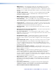
Display 2 Display 4 DVI 201xi Tx DVI 201xi Tx Display 1 DO NOT CONNECT OUTPUTS TO LAN LOCAL MONITOR OUTPUT DVI-D INPUT REMOTE DDC EDID MINDER EDID STORE DEFAULT EDID SN XXXXXXXX E XXXXX 00/00 DVI DL TX POWER 12V 0.4A MAX OUTPUTS 1 2 CONTROL PASS-THRU Tx Rx ON ON OFF Display 3 1 2 3 DVI 201 Rx INPUTS POWER 12V 0.
DVI Flat Panel Display CONTROL PASS THRU Tx Rx DVI-D OUTPUT DVI 201 Rx SERIES DVI Equipped PC DVI 201 Rx Twisted Pair Receiver Extron DTP 26 Cable DVI INPUT LOCAL OUTPUT DVI INPUT LOCAL OUTPUT DVI 200 Tx SERIES DVI 200 Tx SERIES DVI 201 Tx Twisted Pair Transmitter DVI 201 Tx Extron DTP 26 Cable Twisted Pair Transmitter Short DVI Cable Remote User and Administration Control PC CONTROL PASS THRU Tx Rx DVI-D OUTPUT DVI 201 Rx 5 6 DVI-D INPUTS 3 4 1 2 7 8 5 6 DVI-D OUTPUTS 3 4 7
Installation This section describes the rear panels of the DXP switchers and provides instructions for cabling. It covers the following topics: • Rear Panels • Connections Rear Panels Most of the connectors are on the rear panels of the DXP switchers. The following figures show the rear panels of a DVI model and an HDMI model. 1 3 2 4 6 4 1 2 7 8 5 6 3 4 7 8 LISTED 1T23 U SI.T.E. Figure 4.
NOTE: Figure 5 on the previous page shows a DXP 88 HDMI, with eight HDMI input connectors and eight HDMI output connectors. The rear panels of the other three DXP HDMI models are identical to this model except for the number of inputs and outputs: • DXP HDMI 84 – 8 inputs and 4 outputs • DXP HDMI 48 – 4 inputs and 8 outputs • DXP HDMI 44 – 4 inputs and 4 outputs a AC power connector — Plug a standard IEC power cord into this connector to connect the switcher to a 100 VAC to 240 VAC, 50-60 Hz power source.
NOTE: LockIt® cable lacing brackets, one for each HDMI input and output connector, are provided with the DXP HDMI. These brackets can be used to secure the HDMI cables to the DXP connectors to reduce stress on the HDMI connectors and prevent signal loss due to loose cable connections. For information on attaching the LockIt brackets, see the LockIt HDMI Lacing Bracket Installation Guide card, available on the Extron website at www.extron.com.
Connections Risk of electric shock. Remove power from the system before making any connections. WARNING: ATTENTION: Use Electrostatic discharge precautions (be electrically grounded) when making connections. Electrostatic discharge (ESD) can damage equipment, although you may not feel, see, or hear it. Ethernet Connection When connecting a computer to the DXP Ethernet port, it is essential that you use the correct Ethernet cables, and that they be properly terminated with the correct pinout.
RS-232 and RS-422 Remote Connections The DXP switchers have two serial ports through which the DXPs can be configured via SIS commands (serial commands that control the switcher through this connector). Remote RS232/RS422 port (rear panel) 1 6 9 5 Figure 9. RS232/RS422 REMOTE Figure 9 shows the pin assignments for the Remote RS232/RS422 connector.
Operation This section describes the DXP front panel controls and the procedures for configuring and operating the DXP switchers.
• Room — A subset of outputs that are logically related to each other, as determined by the operator. The switchers support up to 10 rooms, each of which can consist of 1 to 16 outputs. Each room can have up to 10 presets. • Room preset — A configuration consisting of outputs in a single room that has been stored. When a room preset is retrieved from memory, it becomes the current configuration for the outputs assigned to that room only (none of the other outputs are affected).
Input and Output Buttons Each DXP model has as many input buttons as output buttons, regardless of how many inputs and outputs it actually has. On models with four inputs or outputs, buttons 5 through 8 behave like buttons 1 through 4, selecting inputs or outputs 1 through 4. The following table summarizes the button functions. Primary Functions 1 2 Action: Select an input or output for the tie being created.
Secondary functions (•): • Select a global preset (see “Saving and Recalling Presets” on page 29). • Output 1 only: With the Input 1 button, places the switcher in I/O grouping mode (see “I/O Grouping” on page 32). • Mute and unmute an output (see “Muting and Unmuting Video and Audio Outputs” on page 36). Configuration Port c Config port — This RS-232 port is an alternative to the Remote RS232/RS422 connector on the DXP rear panel (see “g Remote RS232/RS422 connector” on page 9 for a description).
Secondary functions (•): e • In I/O grouping mode, selects group 1 (see “I/O Grouping” on page 32). • In I/O grouping mode, indicates that group 1 is selected. • With the Preset, View <, and Esc > buttons, places the switcher in serial port configuration mode (see “Selecting the RS-232/RS-422 Protocol and Baud Rate (Rear Panel)” on page 44). • Selects 9600 baud for the Remote RS232/RS422 and the RS-232 Config ports in serial port configuration mode.
g Esc > button — The Esc > button does the following: Primary functions (❏): ❏ Cancels operations or selections in progress and resets the front panel button indicators. NOTE: The Esc > button does not reset the current configuration or any presets. ❏ Indicates that the escape function has been activated (blinks once). Secondary functions (•): • In I/O grouping mode, selects group 4 (see “I/O Grouping” on page 32) • In I/O grouping mode, indicates that group 4 is selected.
Secondary functions (•): i • With the Enter button and Audio button, selects between front panel locks (lock mode 2 and lock mode 0) (see “Locking and Unlocking the Front Panel (Executive Modes)” on page 39). • With the Audio button, selects between front panel lock types (lock mode 2 and lock mode 1). • With the Audio button, initiates system reset from the front panel (see “Resetting the System from the Front Panel” on page 40).
Powering On Apply power by connecting the provided IEC power cord to the rear panel IEC connector and to an AC source. The switcher performs a self-test that blinks the front panel button indicators red, green, and amber and then turns them off. An error-free power-up self-test sequence leaves all I/O and control buttons either unlit or showing background illumination. The lit or unlit status of the Video and Audio buttons remains the same as it was when the switcher was previously powered off.
4. Press and release the Enter button to accept the tie or to break an existing tie. 5. Repeat steps 1 through 4 to create or clear additional ties until the desired configuration is complete. NOTES: • Only one input can be tied to an output. If you tie an input to an output that is already tied to another input, the older tie is broken in favor of the newer tie. • If an input with no tie is selected, only the button for the selected input lights (no output buttons light).
3. Press and release the Input 5 button. Press and release the Input 5 button. The button lights amber. INPUTS 1 2 Figure 15. 3 5 4 6 7 8 Select Input 5 4. Press and release the Output 3, Output 4, and Output 8 buttons. Press and release the Output 3, Output 4, and Output 8 buttons. The buttons blink amber to indicate that the selected input will be tied to these outputs.
Example 2: Adding a Tie to a Set of Video Ties In the following example, a new tie is added to the current configuration. The illustrations show the front panel indications that result from your actions. NOTE: This example assumes that you have performed example 1. 1. Press and release the Esc > button. Press the Esc button to clear all selections. C O NT R O L ENTER PRESET VIEW ESC The button blinks once. Figure 19. Clear All Selections 2.
5. Press and release the Enter button. Press the Enter button to confirm the configuration change. ENTER All input and output buttons become unlit or return to background illumination. The Enter button becomes unlit or returns to background illumination. Figure 23. Confirm the Tie The configuration now is: • Input 5 video tied to output 1, output 3, output 4, and output 8 • Input 5 audio tied to output 3, output 4, and output 8 Figure 24.
Example 3: Removing a Tie from a Set of Ties In the following example, an existing tie is removed from the current configuration. The steps show the front panel indications that result from your actions. NOTE: This example assumes that you have performed examples 1 and 2. 1. Press and release the Esc > button. Press the Esc button to clear all selections. C O NT R O L VIEW ENTER PRESET ESC The button blinks once. Figure 25. Clear All Selections 2.
5. Press and release the Enter button. Press the Enter button to confirm the configuration change. ENTER All input and output buttons become unlit or return to background illumination. The Enter button becomes unlit or returns to background illumination. Figure 29. Confirm the Tie Removal The configuration now is: • Input 5 video tied to output 1, output 3, output 4, and output 8 • Input 5 audio tied to output 3 and output 8 • Input 5 video and audio tied to output 3 and output 8 Figure 30.
4. Select the desired input or outputs whose ties you wish to view by pressing the input and output buttons. NOTES: • When you place the DXP in view-only mode, all output buttons without ties light. Likewise, when you press an output button with no ties, all other output buttons without ties light. • To see all ties of the current configuration, press and release each input and output button, one at a time, with the Video and Audio buttons lit.
3. To select both video and audio for viewing, press and release the Video and Audio buttons as necessary until both are lit. Press the Video button to toggle video on and off. Press the Audio button to toggle audio on and off. I/O VIDEO The button lights green when selected. AUDIO The button lights red when selected.
6. Press and release the Video button to toggle it to green and the Audio button to toggle it to either unlit or background-illuminated. Press the Video button to select it. The button lights green when selected. Press the Audio button to deselect it. I/O VIDEO The button is unlit or background illuminated when deselected. AUDIO The output buttons for outputs that are tied to Input 5 light green to indicate Video ties (audio breakaway).
Saving and Recalling Presets The current configuration (0) can be saved as a preset in any one of 32 preset memory addresses. Preset locations are assigned to the input buttons and (where necessary) output buttons. Up to 16 presets can be selected from the front panel to be either saved or retrieved (16 additional presets can be selected via the control software, SIS commands, or the web pages). When a preset is retrieved from memory, it becomes the current configuration.
2. Press and hold the Preset button until it blinks (approximately 2 seconds). (In the example below, preset 2 was not assigned in a previous example.) Preset Assigned Press and hold the Preset button until it blinks. PRESET INPUTS PRESET 2 seconds All buttons with assigned presets light. If you then save the configuration to a lit preset number, the configuration data at that preset location will be overwritten. Figure 39. 1 2 3 4 5 6 7 8 No Preset Assigned Enter Save Preset Mode 3.
2. Press and release the Preset button. Press and release the Preset button. Preset Assigned The Preset button lights. INPUTS 2 1 PRESET All buttons with assigned presets light. 3 4 7 6 5 8 No Preset Assigned Figure 43. Enter Recall Preset Mode 3. Press and release the input or output button for the desired preset. Press and release the Input 1 button. C O NT R O L The button blinks to indicate that this preset number is selected but not recalled.
I/O Grouping I/O grouping allows you to subdivide the front panel control of the matrix into four smaller functional sub-switchers. Inputs and outputs can be assigned to one of four groups or not assigned to any group. When you are creating ties on the front panel, inputs and outputs that are assigned to a group can be tied only to other outputs and inputs within the same group. For example, you cannot tie an input that is assigned to group 1 to an output that is assigned to group 2.
To set up I/O groups using the front panel: 1. Press the Esc button to clear any input, output, or control buttons that may be lit. 2. To enter I/O group mode, press and hold the Input 1 and Output 1 buttons simultaneously until the buttons light to indicate the ungrouped inputs and outputs, then release the buttons. 3. Press and release one of the control buttons to select a group: • Press the Enter button to select group 1. • Press the Preset button to select group 2 (shown at right).
Example 7: Grouping Inputs and Outputs In the following example, several switcher inputs and outputs are assigned to groups. The steps show the front panel indications that result from your actions. 1. Press and release the Esc button. Press the Esc button to clear all selections. C O NT R O L VIEW ENTER PRESET ESC The button blinks once. Figure 47. Clear All Selections 2.
4. Press and release the desired input and output buttons for the group you are creating. (In the example below, inputs and outputs 1 through 4 will comprise group 1.) Press and release the Input 1 through Input 4 buttons. The selected buttons light. INPUTS 1 2 3 4 5 6 7 8 Press and release the Output 1 through Output 4 buttons. The selected buttons light. 1 2 3 4 5 6 7 8 OUTPUTS Figure 50.
7. Simultaneously press and release the Video and Audio buttons to exit I/O group mode. I/O VIDEO AUDIO Press and release both buttons. Figure 53. Deselect I/O Group Mode NOTE: If you do not press any front panel buttons for approximately 30 seconds, the front panel times out and the switcher exits I/O group mode. In this example: • Group 1 consists of inputs and outputs 1 through 4. • Group 2 consists of inputs and outputs 5 through 8.
Example 8: Muting and Unmuting an Output In the following example, several switcher outputs are muted and unmuted. The steps show the front panel indications that result from your actions. 1. Press and release the Esc button. Press the Esc button to clear all selections. C O NT R O L VIEW ENTER PRESET ESC The button blinks once. Figure 54. Clear All Selections 2. Press and release the View button to enter view-only mode. The View button lights red. 3.
4. One at a time, press and hold the Output 3 button and then the Output 4 button until each button begins to blink (approximately 2 seconds). The output 3 and output 4 video and audio signals are muted. Mute outputs one at a time. 3 Press and hold the Output 3 button. 2 seconds NOTE: Video is muted in this example. 4 Press and hold the Output 4 button. 2 seconds Figure 56. 3 The button blinks to indicate that the output is muted. Green = Video is muted. Red = Audio is muted.
Locking and Unlocking the Front Panel (Executive Modes) The matrix switchers have three levels of front panel security lock that limit the operation of the switcher from the front panel: • Lock mode 0 — The front panel is completely unlocked. All front panel functions are available. • Lock mode 1 — All changes are locked from the front panel (except for setting lock mode 2). Some functions can be viewed. • Lock mode 2 — Basic functions are unlocked. Advanced features are locked and can only be viewed.
Selecting Lock Mode 2 or Toggling Between Mode 2 and Mode 1 NOTES: • If the switcher is in lock mode 0 or mode 1, this procedure selects mode 2. • If the switcher is in lock mode 2, this procedure selects mode 1. Toggle the lock on and off by pressing and holding the Video and Audio buttons until the following buttons blink twice (approximately 2 seconds). • The Esc, Video, and Audio buttons blink twice if the DXP is now in lock mode 2.
To reset the switcher to the factory default settings, press and hold the Video and Audio buttons while you apply AC power to the switcher. NOTE: System reset does not reset the Internet protocol (IP) settings or replace user-installed firmware. Press and hold the Video and Audio buttons while you apply power to the switcher. I/O The buttons flash, then become unlit.
Reset Modes Summary Mode Activation Result Purpose/Notes 1 Hold in the Reset button while applying Restores the factory-installed firmware. It power to the switcher. does not clear the current configuration. 3 Hold in the Reset button until the Reset LED blinks once (after approximately 3 seconds); then within 1 second press Reset momentarily (for less than 1 second) . Turns events (such as on and off. During Mode 3 is useful resetting, the Reset LED blinks two times for troubleshooting.
To perform a soft reset of the switcher: 1. Use a small Philips screwdriver to press and hold the rear panel Reset button until the front panel Video and Audio buttons blink once (for an events reset), twice (for a system reset), or three times (for an absolute reset). Release, then immediately press and release again. RESET RESET Events Reset (Mode 3) Reset LED flashes once. 3 seconds RESET Press and hold the Reset button. Front panel I/O buttons flash once. I/O VIDEO Reset LED flashes twice.
Setting the Button Background Illumination The buttons on the front panel can be set to have amber background illumination at all times or the background illumination can be turned off. To toggle the background illumination on and off, press and hold the Input 1 and Input 2 buttons simultaneously until the button background illumination changes (approximately 2 seconds. Press and hold the Input 1 and Input 2 buttons simultaneously to toggle background illumination mode on or off.
3. To change a value, press and release the button that selects the desired value (see figure 65). Press and release the buttons to configure the RS-232/RS-422 port as follows: Baud rate: Enter — 9600 Preset — 19200 View — 38400 Esc — 115200 Serial protocol: Video — RS-232 Audio — RS-422 The selected buttons blink and the others remain lit. In this example, the port is set to RS-422 at 38400 baud. I/O C O NT R O L ENTER PRESET Figure 65.
Configuration Worksheets Instead of trying to remember the configuration for each preset, use worksheets to record this information. Make copies of the blank worksheet on page 48, and use one sheet for each preset configuration. Cross out all unused or inactive inputs and outputs. The worksheet is generic for all models of DXP. Disregard or cross out boxes for inputs and outputs that your switcher does not have.
Worksheet Example 2: Daily Configuration Figure 68 continues from worksheet example 1 by showing the video ties that make up the configuration of preset 1. A solid ink line shows video ties. Input Sources DVI PRO/ DVI PRO/ DVI PRO/ HDMI HDMI HDMI Camera Camera #1 Camera #2 #3 Main podium VTR #1 VTR #2 VTG 400DVI Editing Station #1 Editing Station #2 1 2 3 4 5 6 7 8 1 2 3 4 5 6 7 8 Main hall #1 Main hall #2 Podium monitor #1 Conf.
Worksheet Form Input Sources 1 2 3 4 5 6 7 8 1 2 3 4 5 6 7 8 Output Destinations Preset # Title: Fill in the preset number and use colors, dashes, and so forth to make connecting lines. Disregard or cross out the input and output boxes that do not apply to your switcher.
SIS Configuration and Control This section describes the serial and Ethernet connections through which the Extron Simple Instruction Set (SIS) commands can be issued, and lists the commands that are available for controlling and configuring the DXP switchers.
Ethernet Port The rear panel Ethernet connector on the switcher can be connected to a computer network. Communication between the switcher and the controlling device can be via Extron DataViewer or Telnet (a TCP socket using port 23). The Telnet port can be changed, if necessary, via SIS. For information on connecting via Telnet, see “Connecting as a Telnet Client” on page 127. The Ethernet connection makes SIS control of the switcher possible using a computer connected to the same network.
Connection Timeouts The Ethernet link times out after a designated period of no communications. By default, this timeout value is set to 5 minutes, but the value can be changed (see the Configure current port timeout command in the Command and Response Table for IP-specific SIS Commands, page 71). NOTE: Extron recommends leaving the default timeout at 5 minutes and periodically issuing the Query (Q) command to keep the connection active.
]Password: The switcher initiates the password message immediately after the copyright message when the controlling system is connected using TCP/IP or Telnet and the switcher is password protected. This message means that the switcher requires an administrator or user level password before it will respond to the commands entered via this link. NOTE: The Password prompt is redisplayed if an incorrect password is entered.
Switcher Error Responses When the DXP receives an SIS command and determines that it is valid, it performs the command and sends a response to the host device. If the switcher is unable to perform the command because the command is invalid or contains invalid parameters, the switcher returns an error response to the host.
SIS Commands for DXP Symbol Definitions for DXP ] = Carriage return and line feed } or ¦ = Carriage return (no line feed) • = Space E or W = key NOTE: Input and output numbers in commands may be entered as either one-digit, two- digit, or three-digit numbers. All input and output numbers are reported as two-digit numbers in the response.
X1^ = Voltage Positive or negative voltage and magnitude of power supplies X1& = Temperature Degrees Fahrenheit X1* = Fan speed In RPM X1( = EDID reference file for DDC 01 – 40 32 = 720p (default) data EDID is a communications protocol or instruction set for the identification of display devices to computers using the DDC (Display Data Channel) transmission standard. EDID information consists of the resolution, refresh rate, and pixel clock information of a display device.
EDID Table — DDC Source Selection DXP DVI, DXP DVI Pro, and DXP HDMI DXP DVI Pro and HDMI* X1( Resolution Refresh (Hz) Output 1 21 1280x1024 60 2 Output 2 22 1280x1024 75 3 Output 3 23 1365x768 60 4 Output 4 24 1365x768 75 5 Output 5 25 1366x768 60 6 Output 6 26 1366x768 75 7 Output 7 27 1400x1050 60 8 Output 8 28 1600x1200 60 9 640x480 60 29 480p 10 640x480 75 30 11 800x600 60 12 800x600 13 SIS Value X1( Resolution 1 Refresh (Hz) SIS Value Re
Command and Response Table for DXP SIS Commands ASCII Command Command Response (Host to Switcher) (Switcher to Host) Additional Description Create Ties NOTES: • Commands can be entered back-to-back in a string, with no spaces. Example: 1*1!02*02&003*003%4*8$ • The quick multiple tie and tie input to all output commands activate all I/O switches simultaneously. • The DXP switchers support 1-, 2-, and 3-digit numeric entries (1*1!, 02*02&, or 003*003%).
ASCII Command (Host to Switcher) (Switcher to Host) Response Additional Description Video mute X#*1B Vmt X#*1] Video unmute X#*0B Vmt X#*0] View individual video mute X# B X$] Global video mute Global video unmute Audio mute 1*B 0*B X#*1Z Vmt1] Vmt0] Amt X#*1] Audio unmute X#*0Z Amt X#*0] View individual audio mute X# Z X$] Global audio mute Global audio unmute View output mutes 1*Z 0*Z Amt1] Amt0] X( X( ... X(n] In verbose mode 2 or 3: Mute Output X# video (video off).
Command ASCII Command (Host to Switcher) Response (Switcher to Host) Additional Description Save, Recall, and Directly Write Global and Room Presets (continued) Save current configuration as a room preset Example: Directly write a global preset Example: X^*X*, Rm X^•SprX*] 3*9, Rm03•Spr09] Save the current configuration as preset X* for room X^. The command character is a comma. Save current ties as preset 9 for room 3. E + X& P X@*X#!X@*X# % X@*X#$...
Command ASCII Command (Host to Switcher) Response (Switcher to Host) Additional Description Save, Recall, and Directly Write Global and Room Presets (continued) Rmm X^•Rpr X*] Recall room preset X^*X*. Directly write a room preset E+X^*X* P X@*X#!X@*X#%X@*X#$...X@*X#&} Rmm X^•Spr X*] Example: Command character is a period. Enter as many ties as are valid for this model. Tie all (!), tie RGB (&), tie video (%), and tie audio ($) commands are all valid.
Command ASCII Command Response (Host to Switcher) Additional Description (Switcher to Host) View Ties and Presets (continued) View audio room preset configuration E X^*X**01*2VC} X@•X@•...•X@•Aud] Show room X^, preset X* audio configuration. Show input X@ tied to 16 sequential outputs assigned to room X^, starting from Output 1. NOTE: For all DXP models, the recommended starting output number is 1. View video global preset configuration E X&*1*1VC} X@•X@•...
Command ASCII Command (Host to Switcher) Response Additional Description (Switcher to Host) Digital Sync Validation Processing (DSVP) View connections 0LS X2# X2# X2#...X2#n] Each X2# response indicates presence or absence of horizontal and vertical sync on an input, starting from input 1. n is the maximum number of inputs on your model. I/O Grouping NOTE: The group that is assigned in each of the following I/O grouping commands (X%) must be 1, 2, 3, 4, or 0 (not grouped).
Command ASCII Command Response (Host to Switcher) (Switcher to Host) E X&,X1# NG} Nmg X&,X1#] E 1,Security1NG} Nmg01,Security1] Read global preset name E X& NG} X1#] Example: Write room name E 2NG} E X^,X1# NR} Security2] Nmr X^,X1#] Example: Read room name Write room preset name Example: E 1,Classrm1NR} E X^ NR} E X^*X*,X1# NP} E 1*3,Podium_DVDNP} Nmr01,Classrm1] Additional Description Names Write global preset name Example: Assign global preset X& the name X1#.
ASCII Command Command (Host to Switcher) Response (Switcher to Host) Additional Description HDCP Authorization (DXP DVI Pro and HDMI models only) NOTE: If the source requires HDCP authentication, ensure that HDCP authorization is set to On (the default). HDCP authorization on E E X!*1HDCP} HdcpE X!*1] Set HDCP authorization to On for input X!. HDCP authorization off E E X!*0HDCP} E E X! HDCP} HdcpE X!*0] Disable HDCP for input X!. X2$ ] Show HDCP authorization status X2$ for input X!.
ASCII Command Command (Host to Switcher) Response Additional Description 60-nnn[n]-01] DXP 44 DVI = 43-265-01 DXP 88 DVI = 43-266-01 DXP 44 DVI Pro = 60-875-01 DXP 48 DVI Pro = 60-1009-01 DXP 84 DVI Pro = 60-876-01 DXP 88 DVI Pro = 60-877-01 Show the DXP part number: DXP 44 HDMI = 60-880-01 DXP 48 HDMI = 60-1010-01 DXP 84 HDMI = 60-881-01 DXP 88 HDMI = 60-882-01 (Switcher to Host) Information Requests (continued) Request part number N Firmware Version Queries: NOTE: There are up to three separate
Command ASCII Command (Host to Switcher) Response (Switcher to Host) Additional Description Information Requests (continued) View File Directory Commands: NOTE: The response to the View File Directory command differs, depending on whether the command is sent via an RS-232, RS-422, or Telnet connection, or via a web browser connection.
Command ASCII Command Response (Host to Switcher) (Switcher to Host) E I X! HDCP} X1)] E O X# HDCP} X1)] E I*HDCP} X1) X1)...X1)n] E O*HDCP} X1) X1)...X1)n] Additional Description HDCP Query Commands View HDCP for an individual input View HDCP for an individual output View HDCP status for all inputs View HDCP status for all outputs Show HDCP status X1) for Input X!. View HDCP status X1) for Output X#.
IP-specific SIS Commands Symbol Definitions for IP-specific Commands X3) = Matrix name Up to 24 alphanumeric characters, including hyphens NOTE: The following characters are invalid or not recommended in the name: {space} + ~ , @ = ` [] {} < > ‘ ’ “ ” ; : | \ and ? X3! X3@ X3# X3$ X3% X3^ X3& X3* X3( = Default name = Time and date (for set) = Time and date (for read) = GMT offset = Daylight Saving Time
X4$ = Notification selections, part 2 If X4# = I, then: X4$ = 0 (all inputs) or 1 through 8 (input 1 through input 8) If X4# = F, then: X4$ = 00 (all fans) If X4# = P, then: X4$ = 00 (both power supplies) X4% = Notify when? 0 = no response 1 = fail or missing 2 = fixed or restored 3 = both 1 and 2 4 = suspend X4^ = DHCP 0 = off, 1 = on X4& = Port number 01 through 99 (two ASCII characters) X4* = Baud rate 9600, 19200, 38400, 115200 (default = 960
Command and Response Table for IP-Specific SIS Commands ASCII Command Response Additional Description Set matrix name E X3) CN} Ipn•X3)] X3) can be up to 24 alphanumeric characters or hyphens (-). The last character cannot be a hyphen.
Command ASCII Command (Host to Switcher) Response (Switcher to Host) Additional Description IP Setup Commands (continued) Set e-mail events for recipient E X4# X4!,X4$,X4% EM} Ipe X4# X4!*X4$*X4% X4%...X4%] You must first have set an e-mail recipient for the e-mail account number (X4!), using the separate Set e-mail recipient (CR) command. Example: E I72,0,3EM} IpeI72*0*33333333] E-mail account #72 (recipient 8), JSmith, will receive fail/missing and fixed and restored messages for all inputs.
Matrix Software This section discusses the following topics: • Matrix Switchers Control Program • Creating Button Labels The following software programs accompany the DXP DVI, DXP DVI Pro, and DXP HDMI switchers: • The Extron Matrix Switcher Control Program, which communicates with the switcher via the RS-232/RS-422 port and the Ethernet port, and provides an easy way to set up ties and sets of ties • The Extron Button Label Generator, which enables you to design and print labels for the DXP front pa
Software Operation Via Ethernet When a DXP switcher is connected to a network, any number of users can operate it, locally or remotely, using the Matrix Switcher Control Program (see “Ethernet Connection” on page 10 for connection details). Connection to the switcher via Ethernet can be password protected. There are two levels of password protection: administrator and user. Administrators have full access to all DXP switching capabilities and editing functions.
2. Choose the communication port through which the DXP is connected to the computer: • If you selected a Comm port, check the baud rate displayed in the Comm Port Selection window. To change the baud rate, click the Baud button to display the baud rate pop-up list. (After you click it, this button changes to OK.) Double-click on the desired baud rate (available rates are 9600, 19200, 38400, and 115200; the default is 9600), then click OK and proceed to step 4. Figure 72.
c. Click Connect. • If you logged on using the administrator password, the program connects you to the DXP switcher with all of the administrator rights and privileges. • If you logged on with the user password, the program connects you to the DXP switcher with only user capabilities. If an incorrect password is entered, the program beeps and returns to the password entry display for you to enter another password. 4. The Extron Matrix Switchers Control Program matrix window appears.
Fig_Sample Matrix window with ties Figure 75. Sample Matrix Window with Ties Setting Up the Matrix Window On the matrix window, the inputs and outputs are represented by boxes. You can assign icons that represent your connected devices to each numbered input and output box. 1. Click on an input or an output box. The Input Devices or Output Devices dialog box opens, providing icons for devices that can be connected to a switcher. Figure 76.
2. Click and drag an icon from the devices screen to an input or output box on the matrix window. Repeat for additional devices as desired. 3. In the Caption box, enter a caption for the device, if desired (for example, Camera 2). This caption appears in the descriptive window that pops up when you pass the cursor over an input or output box containing an icon (see the example below). Figure 77. Pop-up Window for Input 4 Containing a Caption 4.
• To view information on a specific input or output device, position the cursor over that device in the matrix window. A pop-up window opens, showing the input and output numbers, names (if captions were specified), details on the connections to that device, and the frequency of the video signal being sent to or from it. Figure 78.
IP Setup The IP Settings/Options window lets you view and, if connected via the RS-232 or RS-422 link or logged on via the Ethernet port as an administrator, edit settings unique to the Ethernet interface. To display the IP Settings/Options window, select IP Options from the Tools pull-down menu. Figure 79.
Setting the IP address The Matrix IP Address field contains the IP address of the connected matrix switcher. This value is encoded in the flash memory on the switcher. Valid IP addresses consist of four 1-, 2-, or 3-digit numeric sub-fields separated by periods. Each field can be numbered from 000 through 255. Leading zeros, up to three digits total per field, are optional. Values of 256 and above are invalid. The default address is 192.168.254.
4. Click the Take button for the address change to take effect. NOTE: Editing the Gateway IP Address field while connected via Ethernet can immediately disconnect your computer from the DXP. It is recommended that you connect via RS-232 or RS-422 to edit this field. Setting the subnet mask The Subnet Mask field is used to determine whether the DXP is on the same subnet as the controlling PC or the mail server when you are subnetting.
Setting the local time The Time (local) field displays the current time in the local time zone. If necessary, click the Sync Time to PC button to set the switcher to the internal time on your computer, or adjust the time manually as follows: 1. Click in the Time (local) field. A time editing field appears with the date in the format HH:MM:SS (00:00:00 to 23:59:59). The graphic cursor becomes a text cursor in the time editing field. 2. Edit the field as desired to set the proper time.
Edit the Administrator Password field as follows: 1. Click in the Administrator Password field. The graphic cursor becomes a text cursor. 2. Make any desired changes to the case-sensitive password. 3. Press the key on the keyboard or click in another field to exit the Administrator Password field. 4. Click the Take button for the password change to take effect.
Edit the Mail Server Domain Name field as follows: 1. Click in the Mail Server Domain Name field. The graphic cursor becomes a text cursor. 2. Edit the name as desired. 3. Press the key on the keyboard or click in another field to exit the Mail Server Domain Name field. 4. Click the Take button for the name change to take effect.
6. Use the radio buttons associated with each addressee to select whether the addressee will be e-mailed about failures, fixes, both, or will not be notified. The None radio button is useful for temporarily removing personnel from the e-mail list when they are unavailable, such as when traveling or on vacation. 7. If desired, click the Send test E-mail button (which appears along with the floating input selection box) to test the e-mail function. 8.
3. From the Tools menu, select Update Firmware.... The Select Files to Upload to Extron Server... window opens. 4. Navigate to the folder where you saved the firmware file and select the file. Figure 82. Select Files to Upload Window with Firmware File Selected NOTES: • Valid firmware files must have the file extension .S19. Any other file extension is not a firmware upgrade. • The original factory-installed firmware is permanently available on the DXP switcher.
Uploading HTML Files You can create customized HTML pages for the DXP to display. The HTML Files List window (shown below) provides a way to view the contents of the DXP file system and to upload custom HTML pages to the switcher. Figure 83. HTML Files List Window NOTES: • The file listed in figure 83 is shown for example only and may not be present on your switcher. • The HTML Files List window is for inserting your own HTML pages.
Window Buttons, Menus, and Trash Can (Right Column) The buttons, drop-down menus, and trash can icon on the right side of the matrix window perform the following functions: • Power — This button is unavailable for DXP switchers, because the DXP cannot be powered on and off via software. • Executive Mode — Allows you to lock out front panel operations, except for the view-only mode functions (lock mode 2). When executive mode is enabled, the dot to the right of this button is red.
Tools menu The Tools menu contains the following options. Grayed out options are unavailable on your switcher. • Assign Device Icons — Displays the complete set of input and output device icons. You can drag any of these icons to the input and output boxes. To remove an icon from an input or output box, drag an empty square from this list to the input or output box. Figure 84. • Devices Window Edit Device Palette — Allows you to add your own device icon graphics.
• Mute-Output settings — Displays the Channel Mute Settings window. On this screen, use the slider bar to select an output to mute, then select the Video check box in the Mute field. To mute all outputs at once, select the All check box. Figure 86. • Channel Mute Settings Window EDID settings — Opens the EDID Configuration window (shown below), which enables you to set the EDID for selected inputs, and to save Output 1 to any of four user defined outputs. Figure 87.
To select or save an EDID file: 1. Click Advanced Info to open the EDID Record Viewer window, on which you can display the EDID data for any selected output. 2. Save the EDID to a user-defined file (User-assigned EDID 37 through 40). Figure 88. • EDID Record Viewer HDCP status (DVI Pro and HDMI models only) — Opens the EDID Configuration window, which contains a diagram indicating which inputs and outputs have devices connected and which of the connected devices are HDCP-compliant.
• Update Firmware — Allows you to replace the firmware that is coded on the switcher control board (see “Updating the Firmware” on page 85). • IP Options — Allows you to set options for the IP connection (see “IP Setup” on page 79). • HTML File Manager — Displays a list of HTML files installed on the switcher and allows you to upload custom files to the switcher from a connected PC (see “Uploading HTML Files” on page 87).
• Name Presets — Opens the Names for Presets window, which contains a list of all the room and global presets that you have defined. 1. Select a preset from the list and enter a name for it in the text box at the top of the screen. 2. Click Take to confirm the name. Figure 91. Names for Presets Window NOTES: Preset names are limited to 12 upper- and lowercase alphanumeric characters, {space}, and the _ : = and / characters.
• I/O Group settings — Allows you to establish input-output groups. 1. Drag two or more of the small boxes representing inputs or outputs to one of the input or output Group boxes. You can drag boxes to a Group box from the Free section or from another Group section. 2. Repeat step 1 as desired. 3. Click Take to establish the groups. Figure 93.
• Room configuration — Allows you to assign outputs to rooms or delete outputs from rooms. 1. Drag one or more of the small boxes representing outputs to one of the Room boxes. 2. Repeat step 1 as desired to form additional rooms. 3. Click Take to establish the rooms. NOTE: A room is a subset of outputs that are logically related to each other, as determined by the operator. The DXP switcher supports up to 10 rooms, each of which can consist of from 1 to 8 outputs. Figure 94.
Preferences menu The Preferences menu contains the following options: • Immediate changes — Specifies that the configuration changes you make take effect immediately, without the need to click a Take button. (When you select this option, the Take and Cancel buttons are removed from the matrix window.) • Hold/Verify Changes — Delays implementation of configuration changes until the Take button is clicked. • Ties as Lines — Displays ties as lines between input and output boxes. Figure 96.
• Ties as Crosspoints — Displays ties as a matrix of inputs and outputs. Current ties that have been made are indicated by amber boxes. • To create a tie, click in a crosspoint box. A + sign appears briefly in the box you clicked, indicating a tie has been formed. • To break a tie, click on the desired amber (tied) box. A – sign appears briefly and the amber fill is cleared from the box. Figure 97.
• Numbers in I/O boxes — Displays the input and output numbers in the I/O boxes in the matrix window. You are not able to place icons in the boxes when this option is selected. Figure 98. • I/O Boxes Containing the Input and Output Numbers Catch FPC/other’s Changes — When checked, sets the switcher to report all configuration and setting changes to the Remote RS232/RS422 or Ethernet port connection through which this selection was made.
Help menu From this menu you can open the Matrix Switcher Control Program help file. IP Connection Serial Connection • Contents — Displays the Matrix Switcher + Help program, in which you can find procedures for using the software to control and configure the DXP. • Switcher information — The two sections below the Contents option are not menu options; they display information about your switcher: • • Model — DXP model name • Config — Video and audio matrix size: V(nxn) A(nxn) • Firmware Ver.
3. On the Initialize Emulated Matrix Settings From window, select an emulation file (.mtx extension), then click Open. Figure 99. Selecting an Emulation File NOTE: Selecting the Demo.mtx file provides a sample of a completed matrix setup. Selecting the New.ini file or clicking Cancel provides a blank setup screen to get you started. 4. On the Save Emulated Matrix Settings window, enter a file name under which you want to save any changes to the file, and click Save. Figure 100.
5. On the Emulation Configuration window, select the number of video boards, audio boards, and the matrix switcher model you are configuring, and click OK. Figure 101. Emulation Configuration Window 6. Continue using the program as described under “Using the Software” on page 73.
Using the Button Label Generator The Button Label Generator software creates labels for the DXP input and output buttons. You can create labels with names, alphanumeric characters, icons, and even colored bitmaps for easy and intuitive input and output selection. See “Replacing Button Labels” on the next page for procedures for removing and replacing the button covers and changing the labels.
5. After creating the labels, print them by selecting Print from the File pull-down menu in the upper-left corner of the Button Label Generator window. To save the button label set as an .xml file on your computer, select Save As from the File menu and enter a name for the label file. Replacing Button Labels The button assembly consists of a clear lens cap, the button label, and a white diffuser. Remove the button assembly from the DXP as follows: 1.
Blank Button Labels DXP DVI, DXP DVI Pro, and DXP HDMI Series • Matrix Software 104
HTML Operation This section provides procedures for accessing and using the DXP embedded web pages. The following topics are included: • Accessing the Web Pages • Special Characters • Status Tab • Configuration Tab • File Management Tab • Control Tab The DXP can be controlled and operated through its Ethernet port, connected via a network and using a web browser such as Microsoft Internet Explorer®.
Figure 104. Example of a Network Password Dialog Box 5. In the Password field, enter the appropriate administrator or user password. If desired, select the check box to have the system input your password the next time you enter your DXP IP address. Click OK. NOTE: A User name entry is not required. The DXP switcher checks several possibilities, in the following order, and then responds accordingly: • If the address includes a specific file name, such as 10.13.156.10/ file_name.
Status Tab The Status tab lets you access the System Status and the DSVP and HDCP pages. System Status Page The System Status page provides an overall view of the status of the matrix switcher, including individual voltages and serial port status (if applicable). The System Status page is the default page that the switcher downloads when you connect to it. You can access the System Status page from other pages by clicking the Status tab. Figure 105.
DSVP and HDCP Page You can view a snapshot-in-time of the frequencies of connected inputs on the Digital Sync Validation Processing (DSVP) and High-bandwidth Digital Content Protection (HDCP) page. To display the DSVP statuses, select the Status tab, then click DSVP and HDCP link on the left sidebar menu to display the DSVP and HDCP page. NOTE: The DXP DVI (non-Pro) models have a DSVP link on the side-bar instead of DSVP and HDCP, because those models do not support HDCP.
Configuration Tab Click the Configuration tab to access the System Settings, Passwords, Email Settings, and Firmware Upgrade pages. System Settings Page The DXP switcher displays the System Settings page when you click the Configuration tab. The screen consists of fields in which you can view and edit IP administration and system settings.
IP Settings Fields The fields in the IP Settings section provide a location for viewing and editing settings unique to the Ethernet interface. After editing any of the settings on this page, click the Submit button at the bottom of the section. Unit Name field The Unit Name field contains the name used as the “from” information when the DXP e-mails notification of its failed or repaired status. You can change this name field to any valid name, up to 24 alphanumeric characters.
Date/Time Settings Fields The fields in the Date/Time Settings section provide a location for viewing and setting the time functions. Figure 108. Date/Time Settings Fields Change the date and time settings as follows: 1. Click the drop-down box for the desired variable. The variables are month, day, year, hours, minutes, am or pm, and (time) zone. A drop-list appears (the Month list is selected in figure 108). 2. Click and drag the slider or click the Scroll Up until the desired variable is visible.
Passwords Page Access the Passwords page by clicking the Passwords link on the sidebar menu on the Configuration tab. Figure 109. Passwords Page The fields on the Passwords page are used to enter and verify administrator and user passwords. Passwords are case-sensitive and are limited to 12 upper- and lowercase alphanumeric characters. Entering a password To set a password for the DXP: 1. Enter the password in the Administrator Password or the User Password field. 2.
Email Settings Page Access the Email Settings page by clicking the Email Settings link on the sidebar menu on the Configuration tab. The Email Settings page has fields for setting up the DXP e-mail notification capabilities. Figure 110. Email Settings Page For the e-mail settings and for each row of the e-mail notification settings: 1. Click the Edit button at the right of the field to make the field available for editing. The button changes to Save. 2.
Domain Name field The Domain Name field displays the domain name that the DXP switcher uses to log on to the e-mail server. Standard domain name conventions (for example: xxxxx@xxx.com) apply. NOTE: • The following characters are invalid or not recommended in a domain name: + ~ , = ` [ ] { } < > ‘ ’ “ ” ; : | \ ? and {space}. • The @ character is acceptable only as the lead-in to the domain name (such as @folklore.net).
Fig_E-mail Options menu Figure 111. Email Options Menu on the Email Settings Page The Suspend option is useful for temporarily removing personnel from the e-mail list when they are unavailable, such as traveling or vacation. Deleting an e-mail addressee and clicking the Save button removes the recipient from e-mail notification completely.
2. Access the DXP web pages. 3. Select the Configuration tab. 4. On the Configuration page, click the Firmware Upgrade link on the left side. 5. Click the Browse button. A Choose File to Upload window opens. 6. Navigate to the folder where you saved the firmware upgrade file and select the file. Figure 113. Choose File Window with a Firmware File Selected ATTENTION: Valid firmware files must have the file extension .S19. Any other file extension is not a firmware upgrade.
File Management Tab To delete files (such as HTML pages) from the switcher or to upload your own files, click the File Management tab. The switcher displays the File Management page. Figure 114. File Management Page NOTE: The files listed in figure 114 are shown for example only and may not be present on your switcher. Uploading Files Files to be uploaded to the DXP must contain only valid alphanumeric characters and underscores.
Adding a Directory 1. Enter the new directory name in the Dir: field following the slash (/). (The / stands for the root or parent directory.) 2. Click the Add Dir button. 3. With the directory name displayed, perform the uploading files procedure described in the previous section to add a file to the directory. The directory name appears at the top of the Files column, preceded by a slash (/).
Control Tab Use the Control tab to access the Set and View Ties page (click the User Control link) and the Global Presets page (click the Presets link). Set and View Ties Page On the Set and View Ties page, you can create and undo ties, mute and unmute outputs, and assign EDID values to inputs (see figure 115). To access the Set and View Ties page, select the Control tab, then click User Control in the left sidebar menu. Figure 115.
Fig_Tie info popup Figure 116. Pop-up Field Providing Formation About a Button Tie • To tie an input to all outputs, click that input number, located at the left of the matrix. 2. Click the Take button to make the configuration changes or Cancel button to abandon the changes. • Input Adjustments — Contains an HDCP Authorized check box for each input. For the desired input, select this check box to turn on HDCP authorization or clear the box to turn authorization off.
Global Presets Page You can save and recall global presets from the Global Presets page. To access the Global Presets page, click the Control tab, then the Presets link on the left sidebar menu. Figure 117. Global Presets Page Saving a preset Save the current configuration (configuration 0) as a preset as follows: 1. Click the Save Preset button. It changes to Select Preset.... 2. Select the desired preset by clicking one of the preset buttons.
Reference Information This section provides reference information on the DXP DVI Pro and DXP HDMI.
Optional Accessories The following optional accessories can be purchased for use with the DXP DVI, DXP DVI Pro, or DXP HDMI. Accessory Part Number MKP 2000 Matrix Switcher X-Y Remote Control Panel (black) 60-682-02 MKP 3000 Matrix Switcher X-Y Remote Control Panel (black) 60-708-02 9-pin D female to 2.
• Mechanical loading — Mount the equipment in the rack so that uneven mechanical loading does not create a hazardous condition. • Circuit overloading — When connecting the equipment to the supply circuit, consider the connection of the equipment to the supply circuit and the effect that circuit overloading might have on overcurrent protection and supply wiring. Consider equipment nameplate ratings when addressing this concern.
IP Addressing What is an IP Address? An IP address is a 32-bit binary number that is used to identify each device on an Ethernet network. This number is usually represented by four decimal numbers (called “octets”), each in the range of 0 through 255 and separated by dots; for example, 198.123.34.240. This is called “dotted decimal notation.
The following is an example of an invalid Class C addressing scheme: Device IP Address Matrix Switcher Control Software computer 208.132.180.41 DXP DVI Pro switcher 192.157.180.42 NOTE: The above addresses are invalid because the network identifier for each address is not the same even though each IP address is unique. You can perform a test from your computer to check that a device at a particular address is responding correctly or to determine its address (see “Pinging for the IP Address,” below).
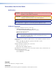
3. Click OK. A command window opens. 4. At the command prompt, enter ping IP address. The computer returns a display similar to figure 119. The line Pinging ... reports the actual numeric IP address, regardless of whether you entered the actual numeric IP address or an alias name. C:\>ping 192.168.254.254 Pinging 192.168.254.254 with 32 bytes of data: Reply Reply Reply Reply from from from from 192.168.254.254: 192.168.254.254: 192.168.254.254: 192.168.254.
Operating using Telnet This guide does not detail all of the operations and functionality of Telnet; however, some basic level of understanding is necessary for operating the DXP switcher via Telnet. Connecting to the DXP (Open command) You connect to the DXP Plus switcher using the Open command. After your computer is connected to the switcher, you can enter the SIS commands the same as you would if you were using the RS-232 link. Connect to the DXP as follows: 1.
Setting carriage return-line feed Unless commanded otherwise, Telnet transmits a line feed character only (no carriage return) to the connected switcher when you press the key. This is the correct setting for SIS communication with the switcher. The Telnet set crlf command forces Telnet to transmit carriage return and line feed characters when is pressed; however, if crlf is set, the SIS link with the switcher does not function properly.
Subnet masks and octets The subnet mask (figure 122) is used to determine whether the local and remote devices are on the same subnet or different subnets. The subnet mask consists of four numeric octets separated by dots. Each octet can be numbered from 000 through 255. Leading zeros, up to three digits total per octet, are optional. Each octet typically contains either 255 or 0.
Extron Warranty Extron Electronics warrants this product against defects in materials and workmanship for a period of three years from the date of purchase.