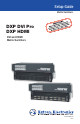
Setup Setup Guide Guide Matrix Switchers DXP DVI Pro DXP HDMI DVI and HDMI Matrix Switchers 68-1370-50 Rev.
Safety Instructions • English Warning This symbol is intended to alert the user of important operating and maintenance (servicing) instructions in the literature provided with the equipment. Power sources • This equipment should be operated only from the power source indicated on the product. This equipment is intended to be used with a main power system with a grounded (neutral) conductor. The third (grounding) pin is a safety feature, do not attempt to bypass or disable it.
安全须知 • 中文 警告 这个符号提示用户该设备用户手册中 有重要的操作和维护说明。 电源 • 该 设 备 只 能 使 用 产 品 上 标 明 的 电 源 。 设 备 必须使用有地线的供电系统供电。 第三条线 (地线)是安全设施,不能不用或跳过。 这个符号警告用户该设备机壳内有暴 拔掉电源 • 为安全地从设备拔掉电源,请拔掉所有设备后 或桌面电源的电源线,或任何接到市电系统的电源线。 露的危险电压,有触电危险。 电源线保护 • 妥善布线, 避免被踩踏,或重物挤压。 注意 阅读说明书 • 用 户 使 用 该 设 备 前 必 须 阅 读 并 理 解所有安全和使用说明。 保存说明书 • 用户应保存安全说明书以备将来使 用。 遵守警告 • 用户应遵守产品和用户指南上的所有安 全和操作说明。 维护 • 所有维修必须由认证的维修人员进行。 设备内部 没有用户可以更换的零件。为避免出现触电危险不要自 己试图打开设备盖子维修该设备。 通风孔 • 有些设备机壳上有通风槽或孔,它们是用来防止 机内敏感元件过热。 不要用任何东西挡住通风孔。 锂电池 • 不正确的更换电池会有爆炸的危险。 必须使用 与厂家推荐的相同
Conventions Used in this Guide In this user guide, the following are used: CAUTION: NOTE: TIP: A caution indicates a potential hazard to equipment or data. A note draws attention to important information. A tip provides a suggestion to make working with the application easier. WARNING: A warning warns of things or actions that might cause injury, death, or other severe consequences. Copyright © 2012 Extron Electronics. All rights reserved.
Contents Introduction........................................1 Remote Control................................21 About this Guide .................................1 About the DXP DVI Pro and DXP HDMI Series Matrix Switchers ...........1 Application Diagram Examples ..........2 Establishing a Network (Ethernet) Connection ....................21 Connection Timeouts ...................22 Number of Connections ...............22 Verbose Mode ...............................22 SIS Commands .....................
vi DXP DVI Pro and DXP HDMI Series • Contents
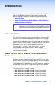
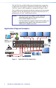
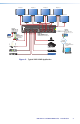
Introduction This section gives an overview of the Extron DXP 44/48/84/88 DVI Pro and DXP 44/48/84/88 HDMI Series Digital Matrix Switchers and provides application examples.
The DXP DVI Pro and DXP HDMI series all provide easy integration in applications that require reliable DVI or HDMI signal routing. (A "DVI Pro" signal is HDCP-compliant; a standard DVI signal is not.) They include several convenience features common to Extron matrix switchers such as the QuickSwitch Front Panel Controller (QS-FPC™), global presets, IP Link®, and Ethernet control. NOTES: • The DXP DVI Pro fully supports HDMI video and embedded audio signals when optional Extron DVI-to-HDMI adapters are used.
Display 5 Display 2 Display 7 Display 6 Display 4 HDMI - HDCP COMPLIANT POWER 12V 0.4A MAX HDMI INPUT 6 3 4 1 2 7 8 5 6 HDMI OUTPUTS 3 4 7 8 ACT 5 HDMI INPUTS LISTED 1T23 U SI.T.E.
4 DXP DVI Pro and DXP HDMI Series • Introduction
Setup This section describes the rear panels of the DXP switchers and provides instructions for cabling. It covers the following topics: •• Setup Procedure •• Rear Panels and Connections •• Front Panel Config Port Setup Procedure Follow these steps to set up and start operating the DXP switcher. See the "Operation" section for additional configuration procedures you may want to perform to set up the switcher. 1. Turn off power to the input and output devices and disconnect their power cords. 2.
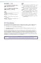
Rear Panels and Connections Most of the connectors are on the rear panels of the DXP switchers. The following figures show the rear panels of the four DVI models and the four HDMI models. NOTE: 1 The illustrations below show DXP 88 DVI Pro and DXP 88 HDMI models, with 8 input and 8 output connectors.
b Input connectors — •• DVI Pro series: Connect DVI-D source devices to these female 29-pin DVI-I input connectors. Only single-link DVI-D signals are supported. •• HDMI series: Connect HDMI source devices to these female 19-pin type A HDMI input connectors. LockIt™ cable lacing brackets, one for each HDMI input and output connector, are provided with the DXP HDMI.
c Output connectors — NOTE: The switchers do not alter the video signal in any way. The signal that is output by the switcher is in the same format as the input signal. •• DVI Pro series: Connect DVI output devices to these female 29-pin DVI-I output connectors. •• HDMI series: Connect HDMI output devices to these female 19-pin type A HDMI output connectors. d Ethernet port — If desired, connect the DXP switcher to a computer, a network WAN or LAN hub, or a control system via this RJ-45 connector.
The cable you use depends on your network speed. The switcher supports both 10 Mbps (10Base-T — Ethernet) and 100 Mbps (100Base-T — Fast Ethernet), half-duplex and full-duplex, Ethernet connections. •• 10Base-T Ethernet requires CAT 3 or higher UTP or STP cable. •• 100Base-T Fast Ethernet requires CAT 5e or higher UTP or STP cable. Terminate the Ethernet cable as required: •• Network connection — Wire as a patch (straight-through) cable.
g Remote RS232/RS422 connector — Connect an RS-232 capable 1 5 6 9 RS232/RS422 REMOTE host device such as a computer or a touch panel control to the switcher via this 9-pin D connector for serial RS-232 or RS-422 control.
An optional 9-pin D to 2.5 mm mini jack TRS RS-232 cable, part number 70-335-01, is available to connect to this port. (The port does not support RS-422.) The figure below shows the pin assignments for this cable. 6 feet (1.8 m) 1 6 6 5 9 9 Part #70-335-01 Tip Ring 9-pin D Connection TRS Plug Pin 2 Pin 3 Pin 5 Computer Rx line Computer Tx line Computer signal ground Tip Ring Sleeve Sleeve (Gnd) Figure 9. 2.
12 DXP DVI Pro and DXP HDMI Series • Introduction
Operation This section describes the DXP front panel controls and the procedures to configure and begin to operate the DXP switchers. For additional operations and more details, see the DXP DVI Pro and DXP HDMI Series User Guide, available from the provided Extron software disc or from the Extron website at www.extron.com. Topics include: •• Front Panel Features •• Operations Front Panel Features The front panels of all DXP models have the same controls and layout (shown below).
c Config port — This RS-232 port is an alternative to the rear panel Remote RS232/RS422 connector. It supports RS-232 only. For more information about the Config port, see "Front Panel Config Port" in the "Setup" section. d Enter button — The Enter button has three primary functions: •• Saves changes that you make on the front panel. •• Indicates that a potential tie has been created but not saved.
Operations Creating a Tie To tie an input to an output: 1. Press and release the Esc button to clear any input button, output button, or control button indicators that may be lit. 2. Press and release the Video and Audio I/O buttons to select or deselect video and audio as desired. I/O Green when selected Off when deselected VIDEO AUDIO Red when selected Off when deselected Figure 11.
Saving or Recalling a Preset 1. Save a preset — Press and hold the Preset button until it flashes. Recall a preset — Press and release the Preset button. Save a preset PRESET Recall a preset PRESET • • Press and hold. 2 seconds Press and release. PRESET Preset button blinks. PRESET Preset button lights. All input and output buttons with assigned presets light red. The configuration data at the assigned preset locations is overwritten. INPUTS 1 2 3 4 5 6 7 8 Figure 14.
•• Advanced features consist of: •• Setting video and audio output mutes •• Creating I/O groups •• Setting the RS-232/RS-422 port protocol and baud rate NOTE: The switcher is shipped from the factory in lock mode 2. Selecting lock mode 2 or toggling between lock modes 2 and 0 NOTES: • If the switcher is in lock mode 0 or 1, this procedure selects mode 2. • If the switcher is in lock mode 2, this procedure selects mode 0 (unlocks the switcher).
Toggle the lock on and off by pressing and holding the Video and Audio buttons until the following buttons blink twice (approximately 2 seconds). •• The Esc, Video, and Audio buttons blink if the DXP is now in lock mode 2. •• The Video and Audio buttons blink if the DXP is now in lock mode 1. Press and hold simultaneously. I/O VIDEO AUDIO 2 seconds I/O VIDEO AUDIO The buttons blink twice. Release the buttons. Figure 17.
Selecting the RS-232/RS-422 Port Protocol and Baud Rate (Rear Panel) NOTE: The serial port settings are protected when front panel lock mode 2 is selected. You can view the settings in lock mode 2 but you cannot change them from the front panel. To enable changes to the mute settings, set the lock mode to 0. To view and configure the serial communications settings for the switcher from the front panel: 1.
3. To change a value, press and release the button that relates to the desired value: Press and release the buttons to configure the RS-232/RS-422 port as follows: Baud rate: Enter — 9600 Preset — 19200 View — 38400 Esc — 115200 Serial protocol: Video — RS-232 Audio — RS-422 The selected buttons blink and the others remain lit. In this example, the port is set to RS-422 at 38400 baud. I/O C O NT R O L ENTER PRESET VIEW ESC VIDEO AUDIO Figure 19. RS-232/RS-422 and Baud Rate Selection 4.
Remote Control This section describes selected SIS commands that pertain to system setup. It also contains instructions for obtaining, installing, and starting the Matrix Switchers Control Program and for accessing the DXP HTML pages.
Connection Timeouts The Ethernet link times out and disconnects after a designated period of no communications. By default, this timeout value is set to 5 minutes but the value can be changed. NOTE: Extron recommends leaving the default timeout at 5 minutes and periodically issuing the Query (Q) command to keep the connection active or disconnecting the socket and reopening the connection when necessary.
EDID (Extended Display Identification Data) EDID is a communications protocol or instruction set for the identification of display devices to computers using the DDC (Display Data Channel) transmission standard. EDID information consists of the resolution, refresh rate, and pixel clock information of a display device. You can apply an EDID to a selected input by selecting one of the following categories of EDID files, shown in the EDID table on the next page.
EDID Table — DDC Source Selection SIS Value Resolution SIS Value Resolution Refresh (Hz) 1 Output 1 21 1280x1024 60 2 Output 2 22 1280x1024 75 3 Output 3 23 1365x768 60 4 Output 4 24 1365x768 75 5 Output 5 25 1366x768 60 6 Output 6 26 1366x768 75 7 Output 7 27 1400x1050 60 8 Output 8 28 1600x1200 60 60 X1( 24 Refresh (Hz) X1( 9 640x480 60 29 480p 2-channel audio 10 640x480 75 30 576p 2-channel audio 60 11 800x600 60 31 720p 2-channel audio 50
Command and Response Table for SIS Commands NOTE: The following table is a partial list of SIS commands. For a complete listing, see the DXP DVI Pro and DXP HDMI Series User Guide, "SIS Configuration and Control" section. Command Function ASCII Command (Host to Switcher) Response (Switcher to Host) Additional Description Output Switching NOTES: Commands can be entered back-to-back in a string, with no spaces. For example: 1*1!02*02&003*003%4*8$.
26 Command Function DXP DVI Pro and DXP HDMI Series • Remote Control ASCII Command (Host to Switcher) Response (Switcher to Host) Additional Description Quick Multiple Tie Tie multiple inputs to multiple outputs, audio and video E+QX@*X#% ... X@*X#!} Tie multiple inputs X@ to multiple outputs X#.
ASCII Command (Host to Switcher) Response (Switcher to Host) Additional Description VmtX#*1] Mute output X# (video off). VmtX#*0] Unmute output X# (video on). View individual output mute X#*1B X#*0B X#B X$] Global Video mute 1*B Vmt1] View video mute status for output X#. For X$: 0 = unmuted, 1 = muted Mute all video outputs. Global Video unmute 0*B Vmt0] Unmute all video outputs. Audio mute AmtX#*1] Mute output X# audio (audio off). AmtX#*0] Unmute output X# audio (audio on).
28 Command Function DXP DVI Pro and DXP HDMI Series • Remote Control ASCII Command (Host to Switcher) Response (Switcher to Host) Additional Description Save and Recall Presets NOTE: If you try to recall a preset that is not saved, the matrix switcher responds with the error code E11. Save current configuration as a global preset Example: Recall a global preset Example: X&, SprX&] 9, Spr09] Save global preset X&. Command character is a comma. Save current set of ties as preset 9. X&.
Command Function ASCII Command (Host to Switcher) Response (Switcher to Host) Additional Description EDID (Extended Display Identification Data) Commands (Continued) DXP DVI Pro and DXP HDMI Series • Remote Control Save output 1 EDID to user location (User-assigned file 37–40) E S X1(EDID} EdidSX1(] Store the EDID of output 1 as userassigned EDID file X1(. X1( = 37–40. Export EDID file data E E X1(EDID} X2)] Export binary data X2) contained in EDID file X1( to the computer.
30 Command Function DXP DVI Pro and DXP HDMI Series • Remote Control ASCII Command (Host to Switcher) Response (Switcher to Host) Q Q X2!] 1.23] S X1^•X1^•X1&•X1*•X$] Additional Description Information Requests (Continued) Query controller firmware version Example: Request system status The factory-installed controller firmware version is 1.23 (sample value only). Display voltages X1^, internal temperature X1&, fan speed X1*, and power supply status X$. For X$: 0 = not OK, 1 = OK Example: S 3.
Command Function ASCII Command (Host to Switcher) Response (Switcher to Host) EX3^CG} ECG} EX4^DH} EDH} E0*X5*TC} E0TC} E1*X5*TC} E1TC} EX5#CV} ECV} IpgX3^] Additional Description IP Setup (Continued) Set gateway IP address Read gateway IP address Set DHCP on and off Read DHCP on/off status Configure current port timeout Read current port timeout Configure global IP port timeout DXP DVI Pro and DXP HDMI Series • Remote Control Read global IP port timeout Set verbose mode Read verbose mode NOTE: X3^
32 Command Function DXP DVI Pro and DXP HDMI Series • Remote Control ASCII Command (Host to Switcher) Response (Switcher to Host) EZXXX} Zpx] Additional Description Reset System reset to factory defaults NOTE: This command excludes IP settings such as IP address, subnet mask, and gateway address. It does not remove the file system. Absolute system reset NOTE: Clear all ties and presets and reset unit to factory default settings.
Installing and Starting the Matrix Switchers Control Program Another way to operate the switcher is via the Matrix Switchers Control Program. This program is contained on the Extron Software Products DVD (included with the switcher). Run this program on a PC connected to either of the switcher serial ports or the Ethernet port. See "d Ethernet port", "g Remote RS232/RS422 connector," and "Front Panel Config Port" in the "Installation" section for connection information.
3. Scroll to the Matrix Switchers Control Program and click Install. Figure 21. Matrix Switchers Control Program Install Link 4. Follow the on-screen instructions. The installation program creates a C:\Program Files\Extron\Matrix_Switchers directory and an “Extron Electronics\Matrix Switchers” group folder. It installs the following four programs: •• MATRIX Switcher + Control Program •• MATRIX Switcher + Help •• Uninstall MATRIX Switcher •• Check for Matrix Updates Starting the Program 1.
4. Click OK. •• If you selected a serial port in step 2, the Matrix Switchers Control Program is ready for operation. •• If you selected IP [LAN] in step 2, the IP Connection window appears. Figure 23. Password Prompt for Control Program a. Check the Matrix IP Address field, which displays the last Matrix IP address entered. If necessary, enter the correct IP address for your switcher in the field. NOTE: 192.168.254.254 is the factory-specified default value for this field. b.
Accessing the HTML Pages Another way to operate the switcher is via its factory-installed HTML pages, which are always available and cannot be erased or overwritten. The switcher HTML pages are accessible through its LAN port, connected via a LAN or WAN, using a web browser such as Microsoft® Internet Explorer® (see d Ethernet port in the "Setup" section for connection information).
5. Enter the appropriate administrator or user password in the Password field and click OK. Figure 25. Password Prompt for Web Pages 6. If you want your password to be filled in every time you open the browser, select the Remember my password check box. The System Status HTML page opens. Figure 26.
Using the Web Pages to Configure the DXP In addition to the System Status page, the DXP has three other pages: Configuration, File Management, and Control. These pages are accessed by clicking the tabs at the top of the screen. Status page This page, shown in figure 27, allows you to monitor the system. The settings shown are not configurable from this page. The page has two sub-pages, which you can display by clicking their links on the sidebar menu: System Status and DSVP and HDCP.
Control page This page lets you control ties and presets on the DXP. Figure 28. Control Web Page Select the following sub-pages from the left sidebar menu. •• The User Control sub-page lets you view and set input to output ties, mute and unmute audio and video signal, and select EDID information for each input. •• On the Presets sub-page, you can save and recall global presets. NOTE: For full details on using the web pages, see the DXP DVI Pro and DXP HDMI User Guide, available at www.extron.com.
40 DXP DVI Pro and DXP HDMI Series • Remote Control
Extron Warranty Extron Electronics warrants this product against defects in materials and workmanship for a period of three years from the date of purchase.
Extron USA Headquarters +800.633.9876 (Inside USA/Canada Only) Extron USA - West +1.714.491.1500 +1.714.491.1517 FAX Extron Asia +800.7339.8766 Inside Asia Only Extron USA - East +1.919.863.1794 +1.919.863.1797 FAX Extron Middle East +971.4.2991800 +971.4.2991880 FAX Extron Europe +800.3987.6673 (Inside Europe Only) +31.33.453.4040 +31.33.453.4050 FAX Extron India 1800.3070.3777 (Inside India Only) +91-80 3055.3777 +91 80 3055 3737 FAX Extron Japan +81.3.3511.7655 +81.3.3511.