User Guide IP Link® IPL T CR48 IP Link Ethernet Control Interface 68-738-05 Rev.
Safety Instructions • English This symbol is intended to alert the user of important operating and maintenance (servicing) instructions in the literature provided with the equipment. This symbol is intended to alert the user of the presence of uninsulated dangerous voltage within the product’s enclosure that may present a risk of electric shock. Warning Power sources • This equipment should be operated only from the power source indicated on the product.
FCC Class A Notice This equipment has been tested and found to comply with the limits for a Class A digital device, pursuant to part 15 of the FCC Rules. Operation is subject to the following two conditions: 1. This device may not cause harmful interference. 2. This device must accept any interference received, including interference that may cause undesired operation.
Contents Introduction............................................. 1 About this Guide.............................................. 1 About the IPL T CR48....................................... 1 Features............................................................ 1 Installation and Operation...................... 3 Installation Overview......................................... 3 Mounting the IPL T CR48.................................. 3 UL Guidelines for Rack Mounting.................. 4 Rack Mounting..
IPL T CR48 • Contents vi
Introduction This section gives an overview of the user guide and describes the Extron® IPL T CR48 IP Link® Ethernet Control Interface and its features. Topics that are covered include: zz About this Guide zz About the IPL T CR48 zz Features About this Guide This guide describes the function, installation, configuration, and operation of the IPL T CR48 Ethernet Control Interface.
Built-in multi-level security — You can control the access to devices attached to the unit. Two levels of password protection provide appropriate security. Contact closure input ports — Can be used to sense when a switch or relay has been activated Supports Ethernet device drivers — Allows for control of up to six Ethernet-enabled A/V devices NOTE: Ethernet driver support requires Global Configurator 3.0 and firmware version 1.15 or higher.
Installation and Operation This section describes the installation and the operation of the IPL T CR48. Topics that are covered include: zz Installation Overview zz Mounting the IPL T CR48 zz Rear Panel Features and Cabling zz Operation Installation Overview To install and set up the IPL T CR48, follow these steps: 1. Turn all of the equipment off.
UL Guidelines for Rack Mounting The following Underwriters Laboratories (UL) guidelines pertain to the installation of an IPL T CR48 unit onto a rack. 1. Elevated operating ambient — If installed in a closed or multi-unit rack assembly, the operating ambient temperature of the rack environment may be greater than room ambient. Therefore, consider installing the equipment in an environment compatible with the maximum ambient temperature specified by the manufacturer [Tma = +32 to +122 °F (0 to +50 °C)]. 2.
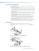
Furniture or Projector Mounting In addition to using the IPL T CR48 unit on a rack, it can be furniture or projector mounted. You can furniture mount the IPL T CR48 using an optional MBU 123 Under-Desk Mount Kit (part #70-212-01) (figure 3). You can also mount the controller to a projector mount pole using an optional PMK 100 Projector Mount (part #70-217-01) (figure 4). Figure 3. Furniture Mounting the IPL T CR48 Mounting Bolt PMK 100 Projector Figure 4.
Power a Power Connection — Plug the external 12 VDC power supply into this connector. The power supply is included with the unit. WARNING: When wiring, the two power cord wires must be kept separate while the power supply is plugged in. Remove power before continuing. CAUTION: Always use a power supply supplied by or specified by Extron. Use of an unauthorized power supply voids all regulatory compliance certification and may cause damage to the supply and the end product.
Ethernet/LAN b LAN port — Plug an RJ-45 jack into this socket to connect the unit to a computer network. Use a straight-through cable to connect to a switch, hub, or router, and a crossover cable to connect directly to a PC. Activity LED — A blinking yellow LED indicates LAN activity. Link LED — A green LED lights to indicate a good LAN connection.
Front Panel Indicators The front panel of the IPL T CR48 has several indicator LEDs that show the current status of communications to and from the unit. A Reset button (b) is also available from the front panel, in a small recess next to the Power LED. IPL T CR48 INPUT R 1 3 2 1 2 4 3 RELAY 1 2 3 5 4 6 7 8 100 5 LINK 6 ACT 7 4 Figure 8. IPL T CR48 Front Panel a b Power LED — A green LED lights to indicate that the unit is receiving power.
IPL T CR48 Reset Mode Summary Mode 1 Activation Result Purpose and Notes Hold down the recessed Reset button while applying power to the IPL T CR48. The IPL T CR48 reverts to the factory default firmware. Event scripting does not start if the unit is powered on in this mode. All user files and settings (such as drivers, adjustments, and IP settings) are maintained. Use mode 1 to revert to the factory default version if incompatibility issues arise with user-loaded firmware.
Connection and Configuration This section discusses how to connect and configure the IPL T CR48. Topics that are covered include: zz Connecting the Hardware zz Configuring the Hardware Connecting the Hardware To connect the IPL T CR48, connect the input and output devices to the unit using figure 9 as a guide. Screen Control Projector Lift Control Blinds Projector Extron IPL T CR48 Ethernet Control Interface 4 3 2 1 8 7 6 T PU 5 IN 1 2 3 4 N LA WER PO V 12 A 0.
Contact Closure Input and Relay Connections Contact closure input connections The IPL T CR48 can be connected to any relay providing a closure to ground (closed = logic 1 and open = logic 0). The contact closure inputs are connected to 5 VDC via a 1k ohm pull-up resistor and must be wired with a ground. This allows the input to be tied to devices such as motion detectors and alarms. You can define what this input triggers via control software. 1. Connect one end of the input cable to a 3.
Initial start up When you power on the IPL T CR48 for the first time, there are two ways to set up the IP address: zz Use the ARP (Address Resolution Protocol) command method. zz Use the direct PC method. The default Web pages that are preloaded on the IPL T CR48 provide a way to reconfigure the unit once it has an active network connection with IP access. These Web pages are compatible with Internet Explorer® (version 6.0 or higher).
4. On the PC, access the command prompt (from the Windows desktop, click Start, then Run, and type Telnet in the Run dialog box) then execute the arp -s command. Enter the desired new IP address for the IPL T CR48 and the MAC address (located on the rear panel of the controller). For example: arp -s 10.13.170.15 00-05-A6-00-0A-90 Figure 10. Executing the ARP Command 5. Execute a ping command by typing ping followed by a space and the new IP address at the command prompt. For example: ping 10.13.170.
Configuring the IPL T CR48 using direct PC connection This type of connection is used initially to connect to and configure the IPL T CR48. The default settings of the unit (IP address, subnet mask, and [optional] administrator name and password) must be changed in order to use the unit on an intranet (LAN) or on the Internet (WAN). 1. Plug one end of a CAT 5 crossover Ethernet cable into the rear panel Ethernet connector on the IPL T CR48. See figure 7 for RJ-45 connector wiring. 2.
Communication and Control This section describes communication with the IPL T CR48 as well as A/V device control. Topics that are covered include: zz Ports Overview zz Communication with the Interface zz Programmer’s Guide for the Telnet and Web Browser zz Device Control zz Troubleshooting Ports Overview Contact Closure Input Ports The contact closure inputs on the IPL T CR48 are able to detect a closed circuit between any of the inputs and ground.
Relay Ports The relay ports can be used for remote switching of low level signals. The relays can be activated via software in three ways: 1. The Port Settings default Web page found under the Configuration tab (figure 16) 2. Telnet 3. An event script running on the IPL T CR48 The Port Settings Web page allows you to turn any of the eight relays on or off.
Accessing and using the Web server To log on and view system status: 1. Double-click the Web browser icon on your Windows® desktop to launch your Web browser. 2. Enter the IP address of the unit (see IPL T CR48 Interface Configuration in the “Connection and Configuration” section) in the Address field at the top of the screen and press the Enter key on your keyboard.
Establishing or changing system or port settings The System Settings screen is used to initially configure or change the configuration of the IPL T CR48. You may be required to change system settings if your network changes or if port settings change as you add or change display devices or switchers. To configure system or port settings: 1. Select the Configuration tab and the System Settings screen (figure 15) is displayed. Figure 15. System Settings Screen 2.
To set or change the passwords: 1. Click the Passwords link on the menu (on the left side of the window). The Passwords screen (figure 17) is displayed. 2. Enter the passwords for the administrator, user, or both, then re-enter the same passwords to confirm. 3. Click Submit to enter the changes of click Cancel to revert to previous settings. If the fields are blank, no passwords have been assigned. Figure 17. Passwords Screen 4.
Editing and adding e-mail alerts If you have created scheduled events or monitoring tasks on the IPL T CR48, you can write an e-mail alert with a message corresponding to that event or task (for example, a timer notification indicating it is time to replace a projector light bulb). The e-mail alert can notify up to eight recipients at one time. To edit notification e-mail addresses from the Email Alerts page: 1. Click Email Alerts on the menu (on the left side of the window).
Sending an e-mail alert through Telnet To complete the process of sending an e-mail alert, you must send it through a Telnet session and receive confirmation. To do so: 1. Open a Telnet session. See Accessing and using Telnet, later in this section, for instructions on how to do this. 2. Use the “Send e-mail” SIS command to send the alert to the e-mail address of a numeric mailbox (figure 18). See Programmer’s Guide for the Telnet and Web Browser, earlier in this section, for specific command code.
Managing files File Management is a useful tool that allows you to use and upload existing and custom Web pages. Custom pages can be developed using a third-party Web page development program such as FrontPage® or Dreamweaver®. File Management also allows you to remove unnecessary or outdated files when they are no longer needed. To add or update files: 1. Select the File Management tab. The File Management screen (figure 20) is displayed. Figure 20. File Management Screen 2.
Programmer’s Guide for the Telnet and Web Browser Using the Command/Response Table The following are either Telnet (port 23) or Web browser (port 80) commands. There are some minor differences when implementing these commands via Telnet or via URL encoding using a Web browser. All commands listed below will work using either connection method, but due to some limitations of the Web browser, the encapsulation characters are modified to make sure that the Web browser will properly handle them.
Symbol definitions are shown below. An ASCII to HEX conversion table is also provided in figure 21. Space ASCII to Hex Conversion Table • Figure 21. ASCII-to-HEX Conversion Table Symbol definitions ] } • X! X# X% X1! X1@ X1# X1$ X1% X1* X1( X2@ = CR/LF (carriage return/line feed) = Carriage return (no line feed) = Space (hard) character = Specific port number (01-99) The port number will be represented as two ASCII characters (2 bytes) = Greenwich Mean Time (GMT) offset value (-12.0 to +14.
X3* = Event data size: bit; Byte (8-bit); Short (16-bit); Long (32-bit) (only first letter is required) NOTE: X3( X4# X4$ X4% X4^ X4& = Event data to write = 0 = off; 1 = on; value = 0-4095, based on 12-bit A to D = Number of bytes to read = E-mail event number: range = 1-64 max = E-mail recipient address: maximum number of characters for full e-mail address is 31 characters. = Name of e-mail file to be sent: the first line of the file is the subject, the rest is the body of the e-mail.
Error responses When the IPL T CR48 receives a valid command, it executes the command and sends a response to the host device. If the unit is unable to execute the command because the command contains invalid parameters, it returns an error response to the host.
Reserved characters Reserved characters should not be encoded when they appear in their conventional meaning in a URL. For example, do not encode the slash ( / ) when using it as part of the URL syntax. Only encode unsafe characters (defined below) in your URLs. The following table lists reserved characters.
IPL T CR48 • Communication and Control 28 X! %2A0O X! O X!*0O X! O Turn relay ON Turn relay OFF View relay status 1Q 2Q 3Q 4Q Query firmware version Query bootstrap version Query factory firmware version Query updated firmware version 4Q 3Q 2Q 1Q 0Q Q X1! (plus web ver.-desc-UL date/time)] X1! (plus web ver.
IPL T CR48 • Communication and Control 29 W %20 CN| WCN| W X1# CT| WCT| E CN} E X1# CT} E CT} Read Unit name Set time/date24 Read time/date W X3$ CZ| WCX| W1DH| W0DH| WDH| W X1$ CI| WCI| WCH| W X1( CS| WCS| W X1$ CG| WCG| W X3# CA| W %20 CA| WCA| W X3# CU| E X3$ CX} E CX} E 1DH} E 0DH} E DH} E X1$ CI} E CI} E CH} E X1( CS} E CS} E X1$ CG} E CG} E X3# CA} E • CA} E CA} E X3# CU} Set daylight saving time Read daylight saving time Set DHCP on24 24 Read IP address Read hardware address (MAC) Set
IPL T CR48 • Communication and Control 30 W %20 CU| WCU| W X2@ CV| WCV| WCK| W X6$ EB| WEB| WCC| E • CU} E CU} E X2@ CV} E CV} E CK} E X6$ EB} E EB} E CC} Set verbose mode24 Read verbose mode Read connection security level Configure broadcast mode View broadcast mode Get connection count {data from the file mypage.html} Send a page GET on port 80 followed by WSF| http://192.168.254.254/mypage.
IPL T CR48 • Communication and Control 31 24 WMH| E MH} W X4% CR| W X4% SM| W X1$ %2C X1% CM| WCM| E X4% CR} E X4% SM} E X1$, X1% CM} E CM} Send e-mail (event)24 W X3% %2C X3^ %2C X3& %2C X3( %2C X3* E| W X3% %2C X3^ %2C X3& %2C X4$ FE| W string %2A X3% %2C X3^ %2C X3& FE| W1AE| W0AE| WAE| E X3%, X3^, X3&, X3(, X3* E} E X3%, X3^, X3&, X4$ FE} E string* X3%, X3^, X3& FE} E 1AE} E 0AE} E AE} 24 27 24 27 27 WX3% %2C X3^ %2C X3& %2C X3* E| X1% X3% X3^ X3& X3* X3( X4$ X4% X4^ X4& X5$ NOTE: X1$ =
IPL T CR48 • Communication and Control 32 WZXXX| WZY| E ZXXX} E ZY} Reset all device settings to factory24 Absolute system reset, but retain IP24 E ZQQQ} WZQQQ| Zpq] This command resets all settings/memories. The ZQQQ command resets everything (all settings, adjustments, the IP address, and subnet mask) to the factory default values. Files in flash memory are also erased by this command. The firmware version does not change. The IP address is reset to 192.168.254.
Device Control Control of A/V devices can be accomplished in several ways once the IPL T CR48 has been connected and configured. These include Web pages, Telnet, and direct port access. Custom Web Pages These pages can either be modified versions of the existing Web pages or new Web pages developed in the field. Web page development can be done with a Web site development tool such as Frontpage or Dreamweaver.
6. If passwords were set up for the connected system, you will be prompted to log in as Administrator or User. Otherwise, the system responds with a . 7. Once you are connected, you can enter serial (ASCII) commands as desired. 8. When you are through entering commands to the IPL T CR48, type quit at the command prompt to quit Telnet. Troubleshooting For best results, make connections in the following order. Turn on: 1. Control devices (such as a PC or laptop) 2. IPL T CR48 3.
Specifications and Part Numbers This section discusses: zz Specifications zz Part numbers for included parts and accessories Specifications Ethernet control interface Connectors ������������������������������������ Data rate ���������������������������������������� Protocols ���������������������������������������� Default settings ������������������������������ 1 RJ-45 female connector 10/100Base-T, half/full duplex with autodetect ARP, ICMP (ping), IP, TCP, UDP, DHCP, HTTP, SMTP, Telnet Link speed an
Mounting Rack mount ����������������������������� Furniture mount ���������������������� Pole mount ������������������������������ Enclosure type �������������������������������� Enclosure dimensions ��������������������� Yes, with optional 1U rack shelf Yes, with optional under desk mounting kit Yes, with optional mini pole mount kit Metal 1.7" H x 4.3" W x 3.0" D (1U high, quarter rack wide) (4.3 cm H x 10.9 cm W x 7.6 cm D) (Depth excludes connectors.) Product weight ������������������������������� 0.
Glossary This section provides definitions of terms related to the IPL T CR48. 10/100Base-T — Ethernet that uses Unshielded Twisted Pair (such as UTP - CAT 5) cable, where the amount of data transmitted between two points in a given amount of time is equal to either 10 Mbps or 100 Mbps. Address Resolution Protocol (ARP) — ARP is a protocol which assigns an IP address to a device based on the MAC or physical machine address of the device.
GlobalViewer (GV) — A set of Web pages (HTML, XML, JS) and graphics that are loaded into the memory of an IPL T CR48. These pages provide an interface for control of devices attached to the IPL T CR48. They communicate with the event scripts running on the unit, and the event scripts issue the commands and queries. This communication between the Web pages and the event scripts occurs through predetermined memory locations in the IPL T CR48.
Extron® Warranty Extron Electronics warrants this product against defects in materials and workmanship for a period of three years from the date of purchase.
Extron USA - West Extron USA - East Extron Europe Extron Asia Extron Japan Extron China Extron Middle East +800.633.9876 Inside USA/Canada Only +800.633.9876 Inside USA/Canada Only +800.3987.6673 Inside Europe Only +800.7339.8766 Inside Asia Only +81.3.3511.7655 +81.3.3511.7656 FAX +400.883.1568 Inside China Only +971.4.2991800 +971.4.2991880 FAX +1.714.491.1500 +1.714.491.1517 FAX +1.919.863.1794 +1.919.863.1797 FAX +31.33.453.4040 +31.33.453.4050 FAX +65.6383.4400 +65.6383.