User’s Manual IRL 20 IR Repeater www.extron.com Extron Electronics, USA Extron Electronics, Europe Extron Electronics, Asia Extron Electronics, Japan 1230 South Lewis Street Anaheim, CA 92805 USA 714.491.1500 Fax 714.491.1517 Beeldschermweg 6C 3821 AH Amersfoort The Netherlands +31.33.453.4040 Fax +31.33.453.4050 135 Joo Seng Road, #04-01 PM Industrial Building Singapore 368363 +65.6383.4400 Fax +65.6383.4664 Kyodo Building 16 Ichibancho Chiyoda-ku, Tokyo 102-0082 Japan +81.3.3511.7655 Fax +81.3.
Precautions Safety Instructions • English This symbol is intended to alert the user of important operating and maintenance (servicing) instructions in the literature provided with the equipment. This symbol is intended to alert the user of the presence of uninsulated dangerous voltage within the product's enclosure that may present a risk of electric shock. Caution Read Instructions • Read and understand all safety and operating instructions before using the equipment.
Quick Start Guide — IRL 20 Step 1 Turn the equipment off and disconnect the equipment from the power source. Step 2 Cut a length (150'/45 m or less) of Extron Comm-Link cable to go between the MediaLink Controller (MLC), MediaLink Switcher, System 5 IP Switcher, or AVT 100 and the IRL 20. See appendix A for cable part numbers. The maximum total distance between an Extron device (switcher, controller) and the IRL 20 is 150’ (45.7 m).
Quick Start Guide — IRL 20, cont’d communications connector. If desired, terminate the other end of the cable and plug it into a communications connector on an optional control module. Step 7 Verify correct wiring and cabling, and test the system: connect the devices to a power source, turn them on, aim an IR remote control at the IRL 20, and check for the appropriate response at the remotely controlled Extron device.
Table of Contents, cont’d IRL 20 1 Chapter One Introduction About the IRL 20 Features ii IRL 20 • Table of Contents
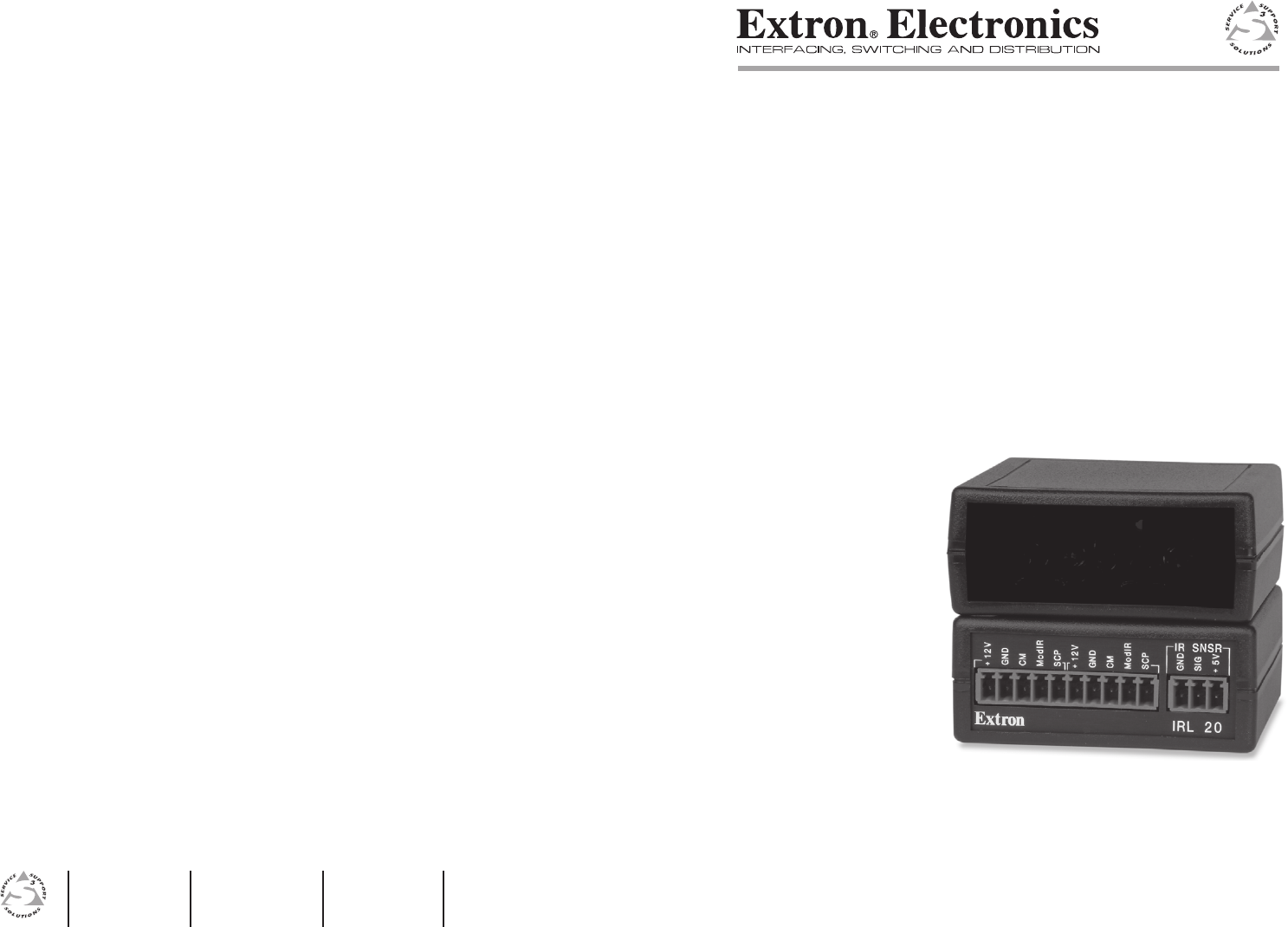
Introduction About the IRL 20 The Extron IRL 20 is a hardwired infrared (IR) signal receiver for use with Extron IR remote controls and an Extron MediaLink™ Controller (MLC), MediaLink Switcher, System 5 IP Switcher, or AVT 100. The IRL 20 receives a signal via its front panel from an Extron IR remote operating at 38 kHz. It can also receive IR input via an optional Extron IR Sensor, which is smaller and less visible than the IRL 20.
1. This unit is not to be connected to a centralized DC power source or used beyond its rated voltage range. 2. The IRL 20 must be installed with accordance with the National Electrical Code and with local electrical codes.
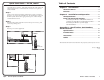
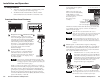
Installation and Operation, cont’d Connecting an IRL 20 to a MediaLink switcher or controller, an AVT 100, or another Extron product SCP GND SIG +5V ModIR CM CM SCP +12V +12V ModIR GND GND Extron IR Sensor IR SNSR IRL 20 Extron System 5 IP V VID VID INPUT 2 Y/C Y/C R H G V B Y VID C IR/SERIAL OUT PROJ CONT C B A RS-232 Tx Rx G Ps G +V S G S G S G L 2 1 R L R L 3 CM/IR/SCP 2 D A B C D E S G +V G CM IR SCP R L 4 R LAN RELAYS A B C C 1 2 C 3 4 C 5
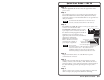
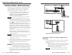
Installation and Operation, cont’d 2. Attach the black wire of an Extron IR Emitter to pin B (ground) and the white striped wire to pin D (IR signal) of a 3.5 mm captive screw connector, and plug it into the IRL 20’s remaining communications connector, as shown below. Two or three emitters can be wired to the same connector, if needed. You can use one 5-pole connector to connect both the power input and the IR Emitter (IR output). It is not necessary to use two connectors. 3.
Specifications, Part Numbers, and Accessories Specifications Included Parts These items are included in each order for a control module: Control/remote — IR repeater Included parts IR controller module ................... Extron IR remote controls only IR output carrier frequency ........ 38 kHz Use the IRL 20 with Extron products only. General External power supply ...............
Specifications, Part Numbers, Accessories, cont’d A-4 IRL 20 • Specifications, Part Numbers, and Accessories