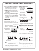
MAV 44 / 48 / 84 / 88 Series Matrix Switchers 68-777-01 Rev.
Precautions Safety Instructions • English Warning This symbol is intended to alert the user of important operating and maintenance (servicing) instructions in the literature provided with the equipment. Power sources • This equipment should be operated only from the power source indicated on the product. This equipment is intended to be used with a main power system with a grounded (neutral) conductor. The third (grounding) pin is a safety feature, do not attempt to bypass or disable it.
FCC Class A Notice N This equipment has been tested and found to comply with the limits for a Class A digital device, pursuant to part 15 of the FCC Rules. These limits are designed to provide reasonable protection against harmful interference when the equipment is operated in a commercial environment. This equipment generates, uses and can radiate radio frequency energy and, if not installed and used in accordance with the instruction manual, may cause harmful interference to radio communications.
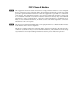
Quick Start — MAV Series AV Matrix Switchers Installation Step 6 — Connect power Step 1 — Mount Definitions If desired, mount the switcher in a rack with the supplied rack ears or mount the switcher under a desk using an Extron MBU 149 1U Enclosure Under-desk mount kit, part #70-222-01.
Quick Start — MAV Series AV Matrix Switchers, cont’d Down ( ) and Up ( ) buttons and LEDs decrease or increase the audio level for the selected input and indicate the decrease and increase. On and are secondary 8-output switchers, functions of the Output 7 and Output 8 buttons. +dB/–dB LEDs indicate the polarity of the audio level setting (+dB = gain, –dB = attenuation). +dB and –dB are secondary functions of the Video and Audio LEDs.
Table of Contents Chapter 1 • Introduction ....................................................................................................... 1-1 About the Switchers ......................................................................................................... 1-2 Features ................................................................................................................................... 1-3 Video features .......................................................................
Table of Contents, cont’d Front panel security lockout (Executive mode) .............................................................. 3-25 Clearing all ties and presets ............................................................................................ 3-25 Resetting the system to factory defaults (audio/video switchers) ................................ 3-26 Memory ............................................................................................................................
Appendix A • Specifications and Part Numbers ................................................... A-1 Specifications ....................................................................................................................... A-2 Part Numbers ....................................................................................................................... A-6 MAV Series AV switchers ..................................................................................................
Table of Contents, cont’d 68-777-01 Rev. D 10 07 All trademarks mentioned in this manual are the properties of their respective owners.
MAV 44 / 48 / 84 / 88 Matrix Switchers 1 Chapter One Introduction About the Switchers Features
Introduction, cont’d Introduction About the Switchers The Extron MAV Series AV matrix switchers (figure 1-1) are a family of broadcast quality matrix switchers that distribute any composite video or S-video input with audio to any combination of outputs. The MAV Series switchers can route multiple input/output ties simultaneously. The MAV Series switchers have a wide array of input and output configurations, video formats, and audio connections.
Inputs Model Part # Outputs Captive Captive RCA RCA Video S-video screw Video S-video screw audio audio audio audio 60-553-22 No 4 4 No No 4 4 No MAV 44 SVA RCA 60-553-32 No 4 No 4 No 4 No 4 MAV 44 SVA MAV 44 AV 60-553-21 4 No 4 No 4 No 4 No MAV 44 AV RCA 60-553-31 4 No No 4 4 No No 4 MAV 48 SVA 60-605-22 No 4 4 No No 8 8 No MAV 48 SVA RCA 60-605-32 No 4 No 4 No 8 No 8 No 4 No 8 No 8 No 8 No No 8 4 4 No MAV 48 AV 60-605-21 4 MAV 4
Introduction, cont’d Audio features Captive screw audio connector (A) models — These switchers input and output balanced or unbalanced stereo audio signals, on 3.5 mm, 5-pole captive screw terminals. RCA audio connector (A RCA) models — These switchers input and output unbalanced stereo audio signals on left and right RCA connectors. Audio input gain/attenuation — You can set the level of audio gain or attenuation (+10 dB to –18 dB) via the RS-232 port or from the front panel.
Global memory presets — 16 global memory presets are a time-saving feature that lets you set up and store input/output configurations in advance. You can then recall those configurations, when needed, with a few simple steps. On each model, there are as many presets available from the front panel as there are input and output buttons: • MAV 44s have 8 presets available on the front panel. • MAV 48s and MAV 84s have 12 presets available on the front panel.
Introduction, cont’d 1-6 MAV 44 / 48 / 84 / 88 Matrix Switchers • Introduction
MAV 44 / 48 / 84 / 88 Matrix Switchers 2 Chapter Two Installation Mounting the Switcher Cabling and Rear Panel Views
Installation, cont’d Installation Mounting the Switcher Keep the switcher out of bright light to prevent interference with the IR signals from the IR 501 remote control. Tabletop use For tabletop use, affix a self-adhesive rubber foot to each corner of the bottom of the switcher. Rack mounting the switcher UL requirements The following Underwriters Laboratories (UL) requirements pertain to the installation of the matrix switcher into a rack (figure 2-1). 1.
Mounting Screws (2 Plcs) Each Side Drill pilot holes 3/32” (2 mm) dia., 1/4” (6 mm) deep. V 8A V8 MA 7 L or 5 L 3 L 1 L R 2 7 L 5 L 3 L 1 NC L SY R R 2 R R R R RS 232 Rack-mount Bracket (Included) R R 8 L R 6 R L R 4 L UTS TP OU L R 8 L R 6 R L R 4 L UTS INP L IN T OU UTS 7 8 TP OU 5 6 3 4 1 2 7 8 UTS INP 5 6 3 4 A 0.
Installation, cont’d Cabling and Rear Panel Views All connectors are on the rear panel. The switcher can be connected to up to eight S-video, composite video, and/or stereo audio sources, depending on the model. The switcher can output to up to eight S-video, composite video, and/or audio devices. Figure 2-2 shows a MAV 44 AV composite video and audio switcher. Figure 2-3 shows a MAV 88 SVA RCA S-video and audio switcher.
Audio input and output connections (audio/video models) The audio level for each input can be individually set, via the front panel or RS-232, to ensure that the level on the output does not vary from input to input. See chapter 3, “Operation”, and chapter 4, “Remote Operation” for details. By default, the audio follows the video switch.
Installation, cont’d 7 Balanced or unbalanced audio output connectors (captive screw audio connector [A] models only) — These 3.5 mm, 5-pole captive screw connectors output the selected unamplified, line level audio. Connect audio devices, such as an audio amplifier or powered speakers to these connectors. See figure 2-6 to properly wire an output connector. R Right 3/16” (5 mm) Max. Unbalanced Stereo Output Tip Ring Ground Tip Ring Left R Left L L Tip NO GROUND HERE.
Using the hardwired IR input on pin 9, you can use a control system with IR-learning capabilities to operate the switcher just as if you were using an IR 501 remote control. The control system must first “learn” the IR command from an IR 501, after which it sends the same commands to the MAV via pin 9. External sync connection The MAV switcher switches between inputs during the vertical interval period, resulting in glitch-free video switching.
Installation, cont’d Figure 2-9 shows another configuration, in which the timing source passes through three video cameras and a video scan converter before connecting to the switcher. This type of video camera is capable of synchronizing with the external timing source for video editing applications.
MAV 44 / 48 / 84 / 88 Matrix Switchers 3 Chapter Three Operation Front Panel Controls and Indicators Operations Optimizing the Audio (Audio/Video Switchers) Troubleshooting Worksheets
Operation, cont’d Operation Front Panel Controls and Indicators The number of input and output buttons and LEDs and other controls and LEDs that are present on each MAV Series AV matrix switcher vary with the number of inputs and outputs and whether the switcher has video only or both video and audio. Not every switcher has every control or indicator described in this chapter.
Definitions The following terms, which apply to Extron matrix switchers, are used throughout this manual: Tie — An input-to-output connection Set of ties — An input tied to two or more outputs. (An output can never be tied to more than one input.) Configuration — Consists of one or more ties or one or more sets of ties Current configuration — The configuration that is currently active in the switcher (also called configuration 0) Global memory preset — A configuration that has been stored.
Operation, cont’d Input and output selection controls and indicators If the switcher has fewer than eight inputs or outputs, it has fewer input or output buttons and LEDs. 3 Input buttons and LEDs — The input buttons and LEDs select and identify inputs. Alternate preset selection function — The input buttons and LEDs also serve as preset selection buttons and indicators, allowing you to select presets to either save or recall.
I/O selection and audio/video controls and indicators (audio/video switchers) 7 I/O and Audio Setup button — • Press and release — Pressing the I/O button cycles through video and audio, video only, or audio only for input and output selection. See the Video and Audio LEDs ( 8 ) for the sequence. • Press and hold — The I/O button also serves as the Audio Setup selection button.
Operation, cont’d 10 Down ( ) button and LED — The button decreases the audio gain for a selected input. Press and release the button to decrease the gain by 1 dB or press and hold the button to decrease the gain by 3 dB per second until the button is released or the lower limit is reached. On 4-output switchers, this button and LED stand alone. On 8-output switchers, this button and LED are secondary functions of the Output 7 button and LED.
2. Plug in all system components and turn on the input devices (such as DVD players, laserdisc players, VCRs, and DSS receivers) and the output devices. 3. Set the input devices to output video using each device’s own operating instructions. 4. Create a tie (see below). The selected input image should appear at the selected output. If no image appears, see “Troubleshooting”, on page 3-27.
Operation, cont’d Example 1: Create a set of video and audio ties The following steps show an example in which input 5 is tied to outputs 3, 4, and 8. The example shows the front panel indications that result from your actions. This example assumes that there are no ties in the current configuration. 1. Audio/video switchers only — Select video and audio for the tie (figure 3-4). Press the button to cycle through the selections. I/O The video LED lights when video is selected.
The current configuration (figure 3-8) is now: • Input 5 video and audio tied to output 3, output 4, and output 8 Input 5 (video/audio) tied to outputs 3, 4, and 8. Input 5 3 4 Output 8 Video Audio Figure 3-8 — Example 1, final configuration Example 2: Add a video tie to a set of video and audio ties The following steps show an example in which a new video tie is added to the current configuration. The example shows the front panel indications that result from your actions.
Operation, cont’d 3. Press and release the Output 1 button (figure 3-11). Press and release the Output 1 button. OUTPUTS 1 2 4 3 5 7 6 8 The Output 1 LED blinks to indicate that the selected input will be tied to this output. = Blinking LED Figure 3-11 — Select the output 4. Press and release the Enter button (figure 3-12). Press the Enter button to confirm the configuration change.
Example 3: Remove a tie from a set of ties This example shows two similar operations: • • Removing an audio tie from a set of ties on an audio/video switcher Removing a tie on a video-only switcher The following steps show an example in which an existing tie is removed from the current configuration. The example shows the front panel indications that result from your actions. This example assumes that you have performed example 1 and example 2. 1.
Operation, cont’d The current configuration (figure 3-18) is now: • • Video — (Video-only switcher) — Input 5 tied to output 1, output 3, and output 8 (Audio/video switcher) — Input 5 video tied to output 1, output 3, output 4, and output 8 Audio — (Audio/video switcher) Input 5 audio tied to output 3 and output 8 Input 5 video tied to outputs 1, 3, 4, and 8. Input 5 audio tied to outputs 3 and 8.
Example 4: View ties by selecting an input The following steps show an example of viewing the video and audio, audio-only, and video-only ties in the current configuration by selecting an input. The example shows the front panel indications that result from your actions. This example assumes that you have performed example 1, example 2, and example 3. 1. Audio/video switchers only — Select both video and audio for viewing (figure 3-19). Press the button to cycle through the selections.
Operation, cont’d 3. Press and release the I/O button (figure 3-21). Press the button to deselect audio. OUTPUTS I/O The video LED lights when video is selected. The audio LED is off when audio is deselected. VID +dB AUD -dB 1 2 4 3 5 6 7 8 The Output 1, Output 3, Output 4, and Output 8 LEDs light to indicate the video ties created in example 1 and 2. Figure 3-21 — Deselect audio to view video only 4. Press and release the I/O button (figure 3-22).
2. Press and release the Output 3 button (figure 3-24). Press and release the Output 3 button. OUTPUTS 2 1 5 4 3 7 6 8 The Output 3 LED lights to indicate that output 3 is selected and it is receiving video or video and audio. The source (or sources, if audio is broken away) is indicated by the Input LED(s). The Output 1, Output 4, and Output 8 LEDs also light to indicate that they are receiving video from the indicated input.
Operation, cont’d 4. Press and release the I/O button (figure 3-26). Press the button to deselect video and select audio. OUTPUTS I/O The video LED is off when video is deselected. The audio LED lights when audio is selected. VID +dB AUD -dB 2 1 3 4 5 6 7 8 The Output 3 LED lights to indicate that output 3 is selected and it is receiving audio. The source is indicated by the Input LED. The Output 8 LED also lights to indicate that output 8 is receiving audio from the indicated input.
Example 6: Save a preset The following steps show an example in which the current configuration is saved as a preset. The example shows the front panel indications that result from your actions. Press and hold the Preset button for approximately 2 seconds until the Preset LED begins blinking (figure 3-27). 1. Press and hold the button. PRESET PRESET 2 seconds The LED blinks to indicate Save Preset mode. Release the Preset button. All input and output buttons with assigned presets light.
Operation, cont’d Example 7: Recall a preset The following steps show an example in which a preset is recalled to become the current configuration. The example shows the front panel indications that result from your actions. 1. Press and release the Preset button (figure 3-29). Press and release the button. PRESET The LED lights to indicate Recall Preset mode. All input and output buttons with assigned presets light.
Adjusting input audio gain and attenuation Audio/video switchers have input audio gain and attenuation adjustments. In Audio Setup mode the audio gain or attenuation of each input can be adjusted through a range of –18 dB to +10 dB. This adjustment range ensures that there is no noticeable volume difference among sources. It also eliminates the need for separate preamps or attenuators when used with professional (higher line level) and consumer (lower line level) audio equipment (figure 3-31).
Operation, cont’d The input audio gain or attenuation can be adjusted from the front panel or by using Extron’s Windows-based control program. 1. Apply audio signals to all inputs to be adjusted. 2. Press and hold the Audio Setup (I/O) button until the Audio Setup LED lights. Release the Audio Setup button. 3. Press and release an input button to select an input. The selected input can be adjusted and is tied to output 1 for measurement or monitoring. a.
Example 8: Adjust the input audio gain The following steps show an example in which an input audio level is viewed and adjusted. The example shows the front panel indications that result from your actions. 1. Press and hold the Audio Setup (I/O) button for approximately 2 seconds (figure 3-32) until the Audio Setup LED lights. Press and hold the button. 2 seconds AUDIO SETUP AUDIO SETUP The LED lights to indicate Audio Setup mode. Release the Audio Setup button. Figure 3-32 — Select Audio Setup mode 2.
Operation, cont’d b. Return to the original audio gain setting by pressing and releasing the or button (the opposite of the button you pressed in step a) the same number of steps you pressed the opposite arrow button in step 1. In example 8, this means pressing the button three times. c.
Resetting audio gain — single input Reset a specified input’s audio gain or attenuation to the factory default (-12 dB for captive screw audio connector [A] models, 0 dB for RCA audio connector [A RCA] models) as follows: 1. Press and hold the Audio Setup (I/O) button for approximately 2 seconds until the Audio Setup LED lights (figure 3-36). Press and hold the button. 2 seconds AUDIO SETUP AUDIO SETUP The LED lights to indicate Audio Setup mode. Release the Audio Setup button.
Operation, cont’d 5. Press and release the Audio Setup button (figure 3-39). All audio changes are saved. Press the Audio Setup button to exit Audio Setup mode. I/O VID +dB AUD -dB All input and output LEDs turn off. AUDIO SETUP The Audio Setup LED turns off.
Front panel security lockout (Executive mode) The MAV Series switchers have a front panel security lockout (Executive mode) feature that limits the operation of the switcher from the front panel and optional IR remote control. When the switcher is locked, the Enter button, I/O button (video only, audio/video, and audio only selection), and all of the front panel audio gain and attenuation functions are disabled.
Operation, cont’d Resetting the system to factory defaults (audio/video switchers) To reset an audio/video switcher to the factory default settings, press and hold the I/O button on the front panel while applying AC power (figure 3-43). Continue to hold the I/O button until all LEDs light and then release the I/O button. The power up sequence completes (all LEDs turn off then turn on and off from left to right, the Video and Audio LEDs turn on, and all other LEDs remain off).
Optimizing the Audio (Audio/Video Switchers) Each individual input audio gain can be adjusted within a range of -18 dB to +10 dB to eliminate noticeable volume differences between sources and to achieve the best headroom and signal-to-noise ratio. Adjust the audio level as follows: 1. Connect audio sources to all desired inputs and connect the audio outputs to output devices such as audio players. See “Audio input and output connections (audio/video models)”, in chapter 2, “Installation”.
Operation, cont’d Worksheets Rather than trying to remember the configuration for each preset, use worksheets to record this information. Make copies of the blank worksheet on page 3-31 and use one for each preset configuration. Cross out all unused or inactive inputs and outputs. If applicable, use different colors for video and audio. Worksheet example 1: System equipment Figure 3-44 shows a worksheet for a MAV 88 AV in a fictional organization with the system hardware annotated.
Worksheet example 2: Daily configuration Figure 3-45 continues from worksheet example 1 by showing the video and audio ties that make up the configuration of preset 1. A solid ink line shows video ties and a dashed pencil line shows the audio ties.
Operation, cont’d Worksheet example 3: Test configuration The A/V system in our fictional organization needs to be fine tuned on a regular basis. Figure 3-46 shows a typical test configuration, with an Extron video test generator (input 8) generating a test pattern to all monitors (outputs 1, 2, 3, 4, and 8). Sound checks are run from the CD player (input 5) to all audio systems (outputs 1, 2, 4, 5, and 8).
MAV 44 / 48 / 84 / 88 Matrix Switchers • Operation 3-31 Title: 2 2 3 3 5 5 Video: Audio: Output destinations 4 4 Fill in the preset number and use colors, or dashes, etc. to make connecting lines. Indicate if the configuration is for Video, Audio, or both.
Operation, cont’d 3-32 MAV 44 / 48 / 84 / 88 Matrix Switchers • Operation
MAV 44 / 48 / 84 / 88 Matrix Switchers 4 Chapter Four Remote Operation Simple Instruction Set Control Matrix Switchers Control Program
Remote Operation, cont’d Remote Operation The MAV AV Series switchers can be remotely controlled via the switcher’s rear panel RS-232 connector (figure 4-1) or using an optional infrared small matrix universal remote control (figure 4-2).
Switcher-initiated messages When a local event such as a front panel operation or an IR 501 command string occurs, the switcher responds by sending a message to the host. The switcherinitiated messages are listed below (underlined). The switcher does not expect a response from the host, but, for example, the host program might request a new status. (C) Copyright 2004, EXTRON ELECTRONICS “MAV nn series”, Vx.xx The copyright message is initiated by the switcher when it is first powered on. Vx.
Remote Operation, cont’d Switcher error responses When the switcher receives an SIS command and determines that it is valid, it performs the command and sends a response to the host device. If the switcher is unable to perform the command because the command is invalid or contains invalid parameters, the switcher returns an error response to the host.
Command/response table for SIS commands Command ASCII Command Response (host to switcher) Additional description (switcher to host) Create ties 1. Commands can be made back-to-back, with no spaces. For example: 1*1!02*02%003*003$4*4!. 2. The quick multiple tie and tie input to all output commands activate all I/O switches simultaneously. 3. The MAVs support 1-, 2-, and 3-digit numeric entries (1*1, 02*02, and 003*003).
Remote Operation, cont’d Command/response table for SIS commands (cont’d) Command ASCII Command Response (host to switcher) Additional description (switcher to host) IR Video mute commands An IR 501 user can mute video and/or audio with a string of IR commands that cannot be duplicated by a computer or control system sending SIS commands. The switcher sends the following responses: IR 501 video and audio mute {none} Mut X3 *1 Output muted.
Command/response table for SIS commands (cont’d) Command ASCII Command Response Additional description (host to switcher) (switcher to host) Enable IR receiver 0*65# IRdisable*0 Enable the IR receiver (allow control by the IR 501). Disable IR receiver 1*65# IRdisable*1 Disable the IR receiver (do not allow control by the IR 501). Read IR receiver enable 65# X10 0= enable, 1 = disable (default).
Remote Operation, cont’d Command/response table for SIS commands (cont’d) Command ASCII Command Response (host to switcher) (switcher to host) Reset global presets Reset individual global preset Reset audio input levels Esc ZG Esc ZA Zpg Zpg X11 Zpa Reset audio output levels Esc ZV Zpv Reset all mutes Reset whole switcher Esc ZZ Zpz Zpx Additional description Resets Esc X11 ZG Esc ZXXX Clear all global presets. Clear global preset X11 .
Command/response table for SIS commands (cont’d) Command ASCII Command Response (host to switcher) Additional description (switcher to host) View ties, gain, mutes, and presets (continued) View global preset configuration Response description: Example (MAV 88 AV): Esc X11 VC X2 1• X2 2• X2 3•...• X2 n•Vid• X2 1• X2 2• X2 3•...• X2 n•Aud n is the highest output number for this model switcher. Show preset X11 ’s video and audio configuration.
Remote Operation, cont’d Loading firmware using an SIS command Firmware can be uploaded two ways: Using the Matrix Switchers Control Program. Using the Esc upload SIS command entered via a communications utility such as HyperTerminal. Extron recommends that you upload firmware using the Matrix Switchers Control Program (see “Updating the firmware” on page 4-15) and reserve this SIS procedure for correcting firmware that has been corrupted and unable to respond to the Matrix Switchers Control Program. 1. 2.
3. Depress the keyboard’s Esc key and then type upload. The computer responds with the “Go” prompt. 4. Click Transfer > Send text file... . 5. Click the Files of type: drop box and select All files (*.*). 6. Navigate to the folder where you saved the firmware upgrade file. Select the file (figure 4-4). Ensure that the firmware upgrade is for the MAV Series AV switcher. Valid version 1.xx firmware files must have the file extension “.HEX”.
Remote Operation, cont’d Matrix Switchers Control Program The Windows®-based Extron Matrix Switchers Control Program, which communicates with the switcher via the rear panel Remote RS-232 port provides an easy way to set up ties and sets of ties. The program is compatible with Windows 2000 and Windows XP. Installing the software The program is contained on the Extron Software Products CD-ROM, disk B.
Follow the on-screen instructions. By default, the Windows installation of the Matrix Switchers Control Program creates a C:\Program Files\Extron\ Matrix_Switcher directory, and it places three icons into a group folder named “Extron Electronics\Matrix Switchers.” The three installed icons are: 4. • MATRIX Switcher+ Control Program • MATRIX Switcher+ Help • Uninstall MATRIX Switcher Using the software Overview 1.
Remote Operation, cont’d 3. The Extron Matrix Switchers Control Program window (figure 4-9 and figure 4-10) displays the current configuration of the attached matrix. Figure 4-9 — Extron Matrix Switchers Control Program window (blank) Figure 4-10 — Sample program window (complete) 4. 4-14 To set up audio to follow video (audio and video have the same tie configuration), select the Follow checkbox at the bottom of the window.
5. To make the control program easier to use, assign a device icon to each input and output. Click on a box that represents an input or output, and drag the desired icon onto the box from the icon palette that appears. 6. To create a tie, drag an input box to one or more output boxes. If the Take button is not grayed out, click the Take button. 7. To remove a single tie, drag the output box to its tied input box or to the trash can. To remove a set of ties, drag the input box to the trash can.
Remote Operation, cont’d 4. Start the Matrix Switchers Control Program and connect to the MAV switcher. See “Using the software”, steps 1 through 3, starting on page 4-13. 5. Click on Tools > Update firmware. If your switcher has version 2.xx firmware files, the Extron Firmware Loader appears (figure 4-12). Proceed to step 6a. If your switcher has version 1.xx firmware files, an open file window appears (figure 4-13). Proceed to step 7. Figure 4-12 — Open window, version 2.xx firmware files 6a.
Figure 4-13 — Open window, version 1.xx firmware files 9. Version 2.xx firmware upload — A status bar, which shows the progress of the upload, appears in the Firmware Loader window (figure 4-14). The firmware upload to the switcher may take several minutes.
Remote Operation, cont’d 10. When prompted, confirm that the firmware version displayed in the firmware loader is correct. Click Ok in the Firmware Update prompt window to exit the firmware loader utility. 11. Version 1.xx firmware upload — A status window appears that shows the progress of the download to the switcher. The firmware download may take a few minutes. The status window advances to 100% and then clears when the download is complete.
Windows menus File menu Save matrix settings as — Saves a complete set of up to 16 presets, plus the last active setting (preset #0), to a file. Saved settings include audio gain settings (if specified), assigned icons, and icon captions. Restore matrix settings from — Loads and activates a previously saved setting file. Save this-session’s settings — Saves a complete set of up to 16 presets, plus the last active setting (preset #0), to overwrite the current file.
Remote Operation, cont’d Audio-Output volume settings — Displays the Mute & Output-Level window (figure 4-16), which displays the output volume level (consumer [-10 dBV] or professional [+4 dBu], for a single output or for all outputs and allows you to change it. This window also allows you to mute and unmute the video and audio output.
Ties as crosspoints — Displays ties as a grid of inputs and outputs (figure 4-18). Existing ties are indicated as orange (video and audio), green (video only), or red (audio only) boxes. New ties that will take effect when you click the Take button are indicated by +. Ties that will be broken when you click the Take button are indicated by –. Figure 4-18 — Ties shown as crosspoints Icons in I/O boxes — Erases any numbers in the I/O boxes in either the the ties-as-lines window or ties-as-boxes window.
Remote Operation, cont’d Using Emulation mode Emulation mode allows you to set up the software without attaching the switcher to the computer. To use Emulation mode: 1. Double-click on the Matrix Switchers Control Program icon in the Extron Electronics group or folder. 2. Choose Emulate, and click OK. 3. Choose an emulation file to open, and click OK. The file DEMO.MTX provides a sample of a completed matrix setup. The file NEW.INI provides a blank setup to get you started. 4.
MAV 44 / 48 / 84 / 88 Matrix Switchers A Appendix A Specifications and Part Numbers Specifications Part Numbers
Specifications andand PartPart Numbers, cont’d Specifications Numbers Specifications Video — composite video and S-video models Routing MAV 44 Series .................. MAV 48 Series .................. MAV 84 Series .................. MAV 88 Series .................. Gain ............................................... Bandwidth .................................... Differential phase error .............. Differential gain error ................. Crosstalk .......................................
Connectors MAV 44/84 composite video models 4 female BNC MAV 44/84 S-video models 4 female 4-pin mini DIN MAV 48/88 composite video models 8 female BNC MAV 48/88 S-video models 8 female 4-pin mini DIN Nominal level ............................... 1 Vp-p for Y of S-video, and for composite video 0.3 Vp-p for C of S-video Minimum/maximum levels ...... 0.4 V to 2.0 Vp-p (follows input) Impedance .................................... 75 ohms Return loss ....................................
Specifications and Part Numbers, cont’d Connectors MAV 44 AV, MAV 44 SVA, MAV 48 AV, MAV 48 SVA (4) 3.5 mm captive screw connectors, 5-pole MAV 44 AV RCA, MAV 44 SVA RCA, MAV 48 AV RCA, MAV 48 SVA RCA 4 pairs of RCA female connectors MAV 84 AV, MAV 84 SVA, MAV 88 AV, MAV 88 SVA (8) 3.5 mm captive screw connectors, 5-pole MAV 84 AV RCA, MAV 84 SVA RCA, MAV 88 AV RCA, MAV 88 SVA RCA 8 pairs of RCA female connectors Impedance ....................................
Control/remote — switcher Serial control port ........................ Baud rate and protocol ............... Serial control pin configurations IR controller module ................... Program control ........................... RS-232, 9-pin female D connector 9600 baud, 8 data bits, 1 stop bit, no parity 2 = TX, 3 = RX, 5 = GND, 9 = hardwired IR IR 501 remote control (optional) Extron’s control/configuration program for Windows® Extron’s Simple Instruction Set (SIS™) General Power ......................
Specifications and Part Numbers, cont’d Part Numbers MAV Series AV switchers Extron Part MAV 44 SVA S-video and audio switcher MAV 44 SVA RCA S-video and audio switcher (RCA connectors) MAV 44 AV composite video and audio switcher MAV 44 AV RCA composite video and audio switcher (RCA connectors) Part # 60-553-22 60-553-32 60-553-21 60-553-31 MAV 48 SVA S-video and audio switcher MAV 48 SVA RCA S-video and audio switcher (RCA connectors) MAV 48 AV composite video and audio switcher MAV 48 AV RCA composite
Optional accessories Extron Part Captive screw connectors with tail (qty.
Specifications and Part Numbers, cont’d Assorted connectors BNC connectors BNC bulkhead connectors, qty. 50 (for custom wall plates) Part # 100-076-51 Pre-cut cables S-video cable is terminated with 4-pin mini DIN connectors on both ends. All Extron BNC cables have male connectors on both ends. A plenum version of the BNC-5 Mini HR cable is also available. S-video Cable Male-to-male cable MHR-2 SVM-M/6 (6 feet/1.8 meters) MHR-2 SVM-M/12 (12 feet/3.7 meters) MHR-2 SVM-M/20 (20 feet/6.
Extron’s Warranty Extron Electronics warrants this product against defects in materials and workmanship for a period of three years from the date of purchase.
www.extron.com Extron Electronics, USA 1230 South Lewis Street Anaheim, CA 92805 800.633.9876 714.491.1500 FAX 714.491.1517 Extron Electronics, Europe Beeldschermweg 6C 3821 AH Amersfoort, The Netherlands +800.3987.6673 +31.33.453.4040 FAX +31.33.453.4050 Extron Electronics, Asia 135 Joo Seng Rd. #04-01 PM Industrial Bldg., Singapore 368363 +800.7339.8766 +65.6383.4400 FAX +65.6383.4664 © 2007 Extron Electronics. All rights reserved.