
User's Manual

4
MLS 608 D Series • Setup Guide (Continued)
RGB
VID
Y/C
B-Y
Y
R-Y
ANALOG OUTPUTS
RS-232
Tx Rx
SPARE
1
MONO AUDIO
2
Component Video –
Connect to these 3 BNCs.
Composite Video –
Connect to this BNC.
RGBHV and RGBS –
Connect to this VGA
connector.
S-video – Connect to
this mini DIN connector.
Mono Audio – Connect
to this captive screw
connector.
L
MONO AUDIO
R
L
MONO AUDIO
R
Unbalanced Output
Balanced Output
Mono output 1-
Sleeve(s)
Mono output 1+
Mono output 2+
Mono output 2-
Sleeve(s)
Mono output 1
Mono output 2
NO GROUND.
NO GROUND.
Wire the audio connector as shown above.
RS-232 Control (Analog Side) –
NOT USED IN THE MLS 608 D SYSTEM.
Do not tin
the wires!
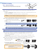
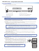
Step 4 — Connect Outputs from MTP/HDMI U R
Digital video — Connect a display to the HDMI
connector for digital video output.
Analog video — Connect the analog outputs as
shown at right.
Audio — Connect a suitable audio device, such as
powered speakers, to the 5-pole captive screw audio
output connector for a balanced or unbalanced, dual
mono audio signal. Wire connector as shown at right.
NOTE: The audio signal is detected on the MTP input and then is distributed to the audio connector for output.
RS-232 control (digital side) — Connect a serial communications port on a display device to the
3.5 mm, 3-pole captive screw connector (labeled RS-232 pass-thru) for pass-through RS-232
bidirectional communication. Wire the connector as shown at right.
NOTE: The RS-232 control port on the analog side is not used in the MLS 608 D system.
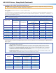
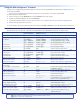
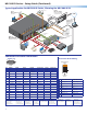
Step 5 — Connect Control Devices
RS-232 control — Connect a host computer or control system (such
as an optional MLC 226) to the 5-pin connector (see m on page 1)
for MLS switcher configuration and control via RS-232 using
Extron software or Simple Instruction Set (SIS) commands.
Wire the MLS as shown at right.
NOTE: This serial port is independent of the front panel
configuration port. Both may be used for MLS control.
RS-232 protocol (default values):
• 38400 baud •1 stop bit • no parity • 8 data bits • no ow control
NOTE: The ‘+’ and ‘-’ pins on this connector can be used to
power a controller, for example an MLC 226 IP and a
connected IRCM-DV+.
RS-232 Insert port (optional) — Connect an optional control
device (for example an MLC 226 IP via the RS-232 display control port)
to the 5-pin connector (see n on page 1) for pass through RS-232
communication to a connected projector or display device.
Wire the connection as shown at right.
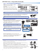
Step 6 — Connect Power
MLS 608 D — Plug in a standard IEC power cord from a 110 - 240 VAC, 50 - 60 Hz power
source into the receptacle (see
a
on page 1).
Optional — Connect the 2-pole power connector (see
e
on page 1)
for remote power to an
MTP transmitter or receiver. Wire the connection as shown at right.
Optional — Connect the “+” and ”-” pins on the RS-232 connector
(see
m
on page 1) for remote
power to an optional controller (such as the MLC 226). See second note, step 4 above.
MTP/HDMI U R — Connect the 2-pole 3.5 millimeter captive screw connector from the 12 VDC,
1.0 A external power supply (provided) to this receptacle on the rear panel, or connect to the 2-pole
power connector (see
e
on page 1) on the MLS 608 D. Wire connector as shown at right.
For both devices, when power is applied the front panel power LED lights.
RS-232
Host
Tx
Rx
MLS 608 D
rear panel
RS-232 Host
port
MLC's
MLS and
Power
ports
A B C D E
DISPLAY
RS-232/IR RS-232 12V
CM/IR/SCP
A B C D E
MLS PWR
AB
Tx/IR
Rx
GROUND
PWR SNS
GROUND
+12V OUT
Rx
Tx
GROUND
GROUND
+12V IN
+12V OUT
GROUND
CONT MOD
IR IN
SCP COM
NORMALLY OPEN
1 2
COMMON
COMMON
COMMON
GROUND
Tx/IR
Tx/IR
Tx/IR
GROUND
GROUND
A
RELAYS
IR/SERIAL OUT
3 4
B
5 6
C
A B C
NOTE: If you use cable that has
a drain wire, tie the drain wire
to ground at both ends.
NOTE: You must connect a ground
wire between the MLC and MLS.
MLS 608 D SA
Rear Panel
MLC 226 IP
Bottom Panel
RS-232 12V
MLS PWR
A B
Rx
Tx
GROUND
GROUND
+12V IN
Ground ( )
Transmit (Tx)
B
Receive (Rx)
A
Transmit (Tx)
Receive (Rx)
B
A
Ground ( )
+12 VDC input
1
BUFFERED OUTPUT
MTP
+
AUDIO
+12 V OUT
PWR OUT=
12W
2
3
6
LR
1
LR
2
LR
3
LR
5
LR
7
LR
8
12 12
MIC/LINE
+ 48V
1
2
LRLR
Tx
+12V
Rx
8
4 (MTP)
CONFIGURABLE ANALOG INPUTS
AUDIO INPUTS
AUDIO OUTPUTS
RS-232
HOST
PWR OUT = 7.2W
DIGITAL OUTPUT
VIDEO + RS-232
ANALOG OUTPUT
DIGITAL INPUTS
5
7
LR
6
Tx
N/A
N/A
Rx
RS-232 INSERT
MLS 608 D SA
100-240V 50/60 Hz
1.2A MAX
12
4/8 OHM - 20W x 2
MLC 226 Display port
DISPLAY
RS-232/IR
Tx/IR
Rx
GROUND
PWR SNS
GROUND
+12V OUT
Ground ( )
Receive (Rx)
Transmit (Tx)
RS-232 INSERT
MLS 608 D rear panel
RS-232 Insert port
Tx Rx
N/A
N/A
RS-232 Device Pins
MTP/HDMI
RS-232
Pass-thru
port
Rx
Ground
TxRx
Tx
Power Supply
Output Cord
2-pole Captive
Screw
Connector
SECTION A–A
Ridges
Smooth
A
A
Tie Wrap
3