User Guide HDMI Switchers MPS 601 Media Presentation Switcher 68-2454-01 Rev.
Safety Instructions Safety Instructions • English WARNING: This symbol, , when used on the product, is intended to alert the user of the presence of uninsulated dangerous voltage within the product’s enclosure that may present a risk of electric shock. ATTENTION: This symbol, , when used on the product, is intended to alert the user of important operating and maintenance (servicing) instructions in the literature provided with the equipment.
FCC Class A Notice This equipment has been tested and found to comply with the limits for a Class A digital device, pursuant to part 15 of the FCC rules. The Class A limits provide reasonable protection against harmful interference when the equipment is operated in a commercial environment. This equipment generates, uses, and can radiate radio frequency energy and, if not installed and used in accordance with the instruction manual, may cause harmful interference to radio communications.
Conventions Used in this Guide Notifications The following notifications are used in this guide: CAUTION: A caution indicates a situation that may result in minor injury. ATTENTION: Attention indicates a situation that may damage or destroy the product or associated equipment. NOTE: A note draws attention to important information.
Contents Introduction............................................................ 1 Configuration Software...................................... 28 About this User Guide......................................... 1 About the MPS 601............................................. 1 Features.............................................................. 2 Installing the Software........................................ 28 Starting the Software......................................... 29 Connect to Online Device.
MPS 601 Switcher • Contents vi
Introduction This section describes this guide and features of the MPS 601, including: • About this User Guide • About the MPS 601 • Features About this User Guide This guide contains information to install, configure, and operate the Extron MPS 601 Media Presentation Switcher. In this guide, the MPS 601 can be referred to as “MPS”, “MPS 601” or “switcher.” About the MPS 601 The Extron MPS 601 is a compact six input, one output media presentation switcher for digital and analog sources.
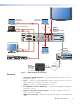
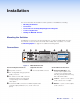
Laptop with HDMI Output Laptop with HDMI Output Flat Panel Display with Speakers HDMI Laptop with VGA Output HDMI Audio Extron MPS 601 HDMI Media Presentation Switcher RGBHV MPS 601 POWER 12V 0.
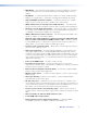
• EDID Minder — Automatically manages EDID communication between connected devices ensuring that all sources power up properly and reliably output content for display. • Key Minder — Continuously verifies HDCP compliance for quick, reliable switching. • Support for computer-video to 1920x1200, including HDTV 1080p 60 Hz and 2K. • Supported HDMI specification features — Include data rates up to 6.75 Gbps, Deep Color up to 12-bit, 3D, Lip Sync, and HD lossless audio formats.
Installation This section describes the installation and the operation of the MPS 601, including: • Mounting the Switcher • Connections • Contact Closure and Tally Output Application Diagrams • Lockit Lacing Brackets • Cabling the MPS 601 Switcher Mounting the Switcher The MPS 601 is housed in a 1U, full rack width rack- or desk-mountable metal enclosure. The switcher can also be surface‑mounted under a table, desk, or podium, or on a wall.
Power and Input A AC power — Connect to standard AC power: 100 to 240 VAC, at 50 or 60 Hz. ATTENTION: • Always use a power supply provided by or specified DC Power Cord Captive Screw Connector by Extron. Use of an unauthorized power supply voids all regulatory compliance certification and may cause damage to the supply and the end product. • Unless otherwise stated, the AC/DC adapters are 3/16" (5 mm) Max. not suitable for use in air handling spaces or in wall cavities.
Control Devices F Contact In and Tally Out — Six 3.5 mm, 3-pole captive scrw connectors for automatic input switching and tally indication using Extron Show Me cables. When a connected contact is grounded, the corresponding input is selected. At the same time, the tally output closes causing the Show Me LED on the connected cable to light (see Contact Closure and Tally Output Application Diagrams on page 7). NOTE: For Show Me cables, the ground pin connection is optional.
Contact Closure and Tally Output Application Diagrams The following diagrams show examples of various connections using the contact enclosure and tally output feature of the MPS 601. MPS 601 POWER 12V -- A MAX INPUTS 1 A OUTPUT 3 5 HDMI RGBHV C G T 1 C G T 3 C G T 5 CONTACT IN / TALLY OUT 2 4 HDMI 6 HDMI B +V REMOTE 2 4 6 RS-232 C G T C G T C G T Tx Rx G MPS 601 Contact Closure and Tally HDMI Video and Embedded Audio VGA/HDMI “Show Me” Cables Display Figure 7.
MPS 601 CCR 306 POWER 12V -- A MAX INPUTS 1 A OUTPUT 3 5 HDMI C G T 1 RGBHV 4 6 HDMI Video Audio Cable Cubby 800 RS-232 C G T C G T C G T Tx Rx G HDMI Video and Embedded Audio Contact Closure Application Diagram with CCR 306 LED (-) NOTE: Determine and select the appropriate PC current-limiting resistor, if needed. Many button switches have the resistor built in.
Lockit Lacing Brackets The included Lockit lacing brackets secure the HDMI cables to the rear panel connectors as shown. The configuration of the HDMI connectors on the MPS 601 rear panel require using a top mount (HDMI output) and a stacked side mount (HDMI inputs 3 and 4 or inputs 5 and 6) installation to secure the four inputs and single output. 1. Loosen the HDMI connection mounting screw from the rear panel enough to allow the LockIt lacing bracket to be placed over it. NOTE: Do not remove the screw.
Cabling the MPS 601 Switcher The switcher can be connected to as many as six input devices (RGBHV and HDMI). It can output to one HDMI device or display. Follow the steps below and the installation example (see Figure 1 on page 2). 1. Turn off power to the switcher and all devices that will be connected to it. 2. Mount the switcher (see Mounting Options on page 44). 3. Attach up to two analog RGBHV, and four HDMI (or DVI-D with appropriate adapters) sources (see Connections on page 4). 4.
Operation This section discusses how to configure and operate the MPS 601. Topics that are covered include: • Front Panel Features • HDCP • Audio Features • Auto-input Switching • Front Panel Lockout (Executive Mode) • Reset Mode • EDID Minder Front Panel Features AB C D INPUTS AUTO SWITCH 1 2 3 4 CONFIG EF G INPUTS 5 6 OUTPUT SIGNAL 1 2 3 4 5 6 HDCP MPS 601 MEDIA PRESENTATION SWITCHER Figure 13.
HDCP The HDMI group is HDCP compliant. When EDID Minder is enabled (default), HDCP is not supported if adapters are used to provide DVI inputs. HDCP communication occurs between the selected input source and the output device directly (pass-though). Audio Features There are three audio modes to customize switching the digital and analog audio inputs to the output. They are selectable using SIS commands (see Audio input mode on page 24) or the PCS configuation software (see Audio Config Page on page 39).
Mode 2 Audio Input A Group Audio follows Input 1 or 2 1 3 MPS 601 A POWER 12V -- A MAX A Analog audio input A is grouped with RGBHV inputs 1 and 2. 5 INPUTS OUTPUT 3 5 HDMI C G T 1 C G T 3 C G T 5 CONTACT IN / TALLY OUT 4 6 HDMI B 2 4 4 6 RS-232 C G T C G T C G T Tx Rx G 6 HDMI HDMI 4 +V REMOTE 2 HDMI 5 • Input 1 selected: RGBHV 1 video and audio input A switch to the HDMI output. • Input 2 selected: RGBHV 2 video and audio input A switch to the HDMI output.
Autodetect for Audio Autodetect for audio is enabled when audio mode 3 is active. Audio InfoFrame data embedded in the digital signal is sampled to determine if audio is present on the selected HDMI stream. • If audio is present on the incoming stream, it is selected for output.
EDID Minder The HDMI and RGBHV input groups feature EDID Minder, ensuring that each input source reads the EDID of the output display even when the input is not selected. The result is the video source powers up properly and reliably outputs content when selected. Depending on the EDID mode selected, the EDID of the connected display is stored in slot 65 (see User assigned EDID Mode on page 16).
User assigned EDID Mode Using SIS commands, an EDID file can be selected from a table of 64 EDID files. Four additional EDID file locations are reserved for user-loaded EDID files. Once a user assigned EDID is selected, it is stored at that input and EDID polling ceases for a connected display. The following table lists the native resolution of each factory EDID file.
EDID Native Resolution Refresh Rate Type Video Format Audio 33 800 x 600 60 Hz PC HDMI 2-Ch 34 1024 x 768 60 Hz PC HDMI 2-Ch 35 1280 x 768 60 Hz PC HDMI 2-Ch 36 1280 x 800 60 Hz PC HDMI 2-Ch 37 1280 x 1024 60 Hz PC HDMI 2-Ch 38 1360 x 768 60 Hz PC HDMI 2-Ch 39 1366 x 768 60 Hz PC HDMI 2-Ch 40 1400 x 1050 60 Hz PC HDMI 2-Ch 41 1440 x 900 60 Hz PC HDMI 2-Ch 42 1600 x 900 60 Hz PC HDMI 2-Ch 43 1600 x 1200 60 Hz PC HDMI 2-Ch 44 1680 x 1050
Remote Communication and Control This section discusses SIS programming and control of the MPS 601 including: • Connection Options • Host-to-MPS Communications • Command and Response Table Connection Options The MPS 601 can be remotely connected to a host computer or other device (such as a control system) attached to the rear panel RS‑232 port or the front panel USB Config port. The switcher can be set up and controlled using Simple Instruction Set (SIS) commands.
Front Panel Configuration Port The USB mini B port is located on the front panel (see figure 15, below). It is used to connect to a host computer for configuration using SIS commands with DataViewer or for updating firmware with the Firmware Loader utility. Both are available at www.extron.com. It may be necessary to install the USB driver to the connected computer.
3. Click Next. The following dialog opens: Found New Hardware Wizard Welcome to the Found New Hardware Wizard This Wizard helps you install software for: Extron USB Device If your hardware came with an installation CD or floppy disk, insert it now. What do you want the wizard to do? 4 Install the software automatically [Recommended] Install from a list or specific location [Advanced] Click Next to continue 5 Next > Cancel Figure 17. Install the Software Automatically 4.
Host-to-MPS Communications The MPS switcher accepts Simple Instruction Set (SIS) commands through the RS‑232 or USB configuration port. SIS commands consist of one or more characters per command field. They do not require special characters to begin or end the command character sequence. Each response to an SIS command ends with a carriage return and a line feed (CR/LF = ]), which signals the end of the response character string. A string is one or more characters.
Command and Response Table Using the Command and Response Table The command and response table is shown on the following pages. Lower case characters are acceptable in the command field only where indicated. Symbols are used throughout the table to represent variables in the command and response fields. Symbol definitions and an ASCII-to-hexadecimal (HEX) conversion table are shown below. Command and response examples are shown throughout the command and response table.
X1* = Mute LED mode 0 = Always on (default). 1 = Off, when muted. 2 = Blink, when muted. X1( = Name is a text string of up to 24 alpha-numeric characters and a minus sign or hyphen (-). No blank or space characters are permitted. No distinction between upper and lower case. The first letter must be a letter, and the last character must not be a minus sign or hyphen. Default: MPS-601. X3) = Pixel phase 0 to 63 (default=32) X3! = Total Pixels +255 of the default value depending on input rate.
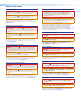
Command and response table for SIS commands Command ASCII Command Response Description Select input X!! In X!•All] Select input X! audio and video. View current input ! E0LS} X! ] View active input X!.
Command ASCII Command (host to switcher) Response (switcher to host) Description Picture Adjustments (RGB Inputs only) NOTE: The specific input must be selected on the front panel in order to make picture adjustments.
Command ASCII Command Response Description Set HDCP authorization per input E E X!*X^HDCP} HdcpE X!*X^] X! = HDMI inputs 3-6 only Set HDCP authorization all inputs E E X^HDCP} HdcpE X^] X^ = 0=blocked View HDCP status E E HDCP} HdcpE X^•X^•X^•X^] See Notes below. View input HDCP status E I X! HDCP} HdcpI X3$ ] See Notes below. View output HDCP status E O HDCP} HdcpO X3$ ] See Notes below.
Command ASCII Command Response I In X! Aflw0•Ausw X1% •Vmt X#•Amt X#] (host to switcher) Information request General information (switcher to host) Description Video input (1-6), Audio input (16), Autoswitch status, Video mute status, Audio mute status. Query model name 1I MPS•601 ] Query part number N 60-xxxx-xx ] Query firmware version Q/q x.xx ] Displays firmware version number to the second decimal. Query firmware version with build *Q/q x.xx.
Configuration Software The Extron Product Configuration Software (PCS) provides a graphical user interface that includes the same functions as those on the front panel and provides an additional way to configure the MPS 601 using a USB or RS-232 connection. This section describes the software installation and operation.
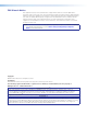
Starting the Software Open the Product Configuration Software program from the Start menu or desktop shortcut. The software window opens with the Connect to Online Device tab open. NOTE: The Start New Device File, which starts the PCS program in emulate mode, is not functional for the MPS 601. Always use the Connect to Online Device tab to connect. Figure 19. Device Selection Window Connect to Online Device The Connect to the Online Device tab connects the software to a specified device. 1.
Using the Software The main PCS window opens on the Configuration page and the Input/Output Config panel selected. Under the device tab, PCS has two drop-down menus on the toolbar: Connections and Tools (see figure 21). Figure 20. New Device Page Connections Menu The Connections menu contains options for connecting, disconnecting, and exiting the program. In the toolbar, click Connections below the device tab. Figure 21.
Disconnect This option disconnects the PCS program from the device. From the Connections menu, click Disconnect. The MPS 601 is disconnected but the PCS program remains open. NOTE: If a device is already disconnected, the Disconnect option is disabled until the device is connected. Exit This option disconnects the MPS 601 (if connected) and closes the application. From the toolbar select Connections > Exit. The application closes. Tools Menu The Tools menu contains the update firmware option.
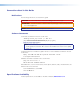
3. Click Browse (see figure 24 on the previous page). 4. Navigate to the desired firmware file and select the device-specific firmware file. Valid firmware files have an .eff or .esf file extension. 5. Click Open. This returns you to the Update Firmware dialog box. 6. In the Update Firmware dialog box, click Update. A progress bar shows the progress of the firmware upload to the device.
Navigating the PCS Application The configuration software opens to two main tabs: Configuration and Hardware. Figure 25. Product Configuration Software - Main Screen Click a tab to change the global navigation bar with icons that open various pages for configuration settings and information (see figures 26 and 27 below for available pages on the configuration and the hardware tabs). Figure 26. Configuration Global Navigation Bar Figure 27.
Configuration Pages The Configuration tab global navigation bar has the following pages: • Input/Output Configuration – Provides an overview of the current inputs and output configuration (see Input/Output Configuration on page 34). • EDID Minder – Provides a list of EDIDs and their current assignments and allows changing them (see EDID Minder Page on page 36).
Output Configuration panel The Output Configuration panel shows the current status of the output and allows color bit depth adjustment. • Output – The number is always 1. • Signal Presence – Indicates an active signal on the output. Corresponds to the front panel output LED (see Front Panel Features on page 11). • HDCP Status – Indicates the HDCP authorization of the output. Corresponds to the front panel HDCP LED (see Front Panel Features on page 11).
EDID Minder Page EDID Minder manages the EDID information between the switcher and one or more input sources. Click the EDID Minder icon on the Global Navigation Bar to open the page. Figure 29. EDID Minder Page The EDID Minder page is divided into five panels: • Filter – Select from the drop-down lists in each category to limit the EDIDs shown in the three EDID screens. • Favorites – Drag and drop frequently used EDIDs from the Available EDID panel below.
Available EDID panel EDID can be stored or imported as custom EDID files. Up to four custom EDID files can be stored in the switcher. Audio settings from custom EDID files take priority over current settings on the input.
Adding EDID to the EDID Library 1. Click Add EDID to Library. The Browse Add EDID to Library dialog box opens. 2. Navigate to the desired EDID file location and select it. NOTE: Valid EDID files have a .bin file extension. 3. Click Open. The EDID is added to the Available EDID list. Image Settings Page From this page, signal sampling and picture control settings for the two analog inputs (inputs 1 and 2) are adjusted.
Audio Config Page The MPS 601 audio inputs have three modes that switch the active digital and analog audio inputs to the output. Figure 31. Audio Configuration Audio Configuration Mode 1 (default) – The associated audio input follows the selected input. • Audio input A follows input 1. When input 1 is selected, RGBHV 1 video and audio input A are routed to the HDMI output. • Audio input B follows input 2. When input 2 is selected, RGBHV 2 video and audio input B are routed to the HDMI output.
Device Settings Page The Device Settings page allows configuration of the input auto‑switching and the tally out LED indication. Click the Device Settings button on the Global Navigation Bar to open the page. Figure 32. Device Settings Page Auto Switch panel In the absense of active video on the selected input, input auto-switch mode automatically switches inputs based on detected input signals. 1. Select the Enable Auto Switch check box to enable auto-input switch mode. 2.
Hardware Pages The Hardware pages contain unit information and options for device information, device naming, executive mode, and reset mode. Click the Hardware tab to open these pages. Figure 33. Hardware Global Navigation Bar Unit Information Page This page gives a non-configurable view of information about the connected device. Click Unit Information to open the page. The following information displays: • Part number – The Extron part number of the connected MPS 601.
Executive Mode Page The Executive Mode page contains options for enabling or disabling the front panel lockout mode. When enabled, executive mode provides security from an accidental or unauthorized front panel button press by locking out the input switching buttons. Click the Executive Mode icon on the Global Navigation Bar to open the page. Figure 36.
Reset Device Page This page allows the user to reset the device. Click Reset Device on the Global Navigation Bar to open the page. Figure 37. Reset Device Page There is one reset option: Reset Device — Resets all settings on the device to factory defaults. To reset the device: 1. Click Reset. The Reset Device dialog opens. 2. Click Reset to continue or Cancel to abort the reset. 3. When the reset is complete, a confirmation dialog opens. 4. Close the dialog box.
Reference Information This section discusses the specifications, part numbers, and accessories for the MPS 601. Topics that are covered, include: • Mounting Options • DataViewer • Updating Firmware Mounting Options The MPS 601 is housed in 1U tall, half rack width, six inches deep metal enclosure, rack- or desk-mountable. The switcher can be mounted through-desk or rack mounted with optional rack mount brackets.
Rack Mounting #10-32 Screw w/ Nylon Captive Cap Washer Figure 38. Mounting the Switcher Table or Wall Mounting The table or wall mounting brackets extend approximately 1/4 inch (6.4 mm) above the top surface of the switcher enclosure allowing for an air space between the enclosure and the surface. Table or wall mount the switcher as follows: 1. Attach the table or wall mounting brackets to the switcher with the eight #8 machine screws (figure 37 on page 44). 2.
Through-desk Mounting Mount the switcher through a desk or podium as follows: 1. Attach the mounting brackets to the switcher with the machine screws provided. 2. Cut the proper sized hole in the mounting surface. 3. Hold the switcher with the attached brackets against the underside of the table or other furniture. Mark the location of the screw holes of the bracket on the mounting surface. 4. Drill 3/32 inch (2 mm) diameter pilot holes, 1/4 inch (6.
DataViewer DataViewer is an enhanced terminal emulation program that facilitates analysis of RS-232, USB, and TCP/IP communication with Extron devices. The software allows users to send commands to a device and view the responses in ASCII or hexadecimal format. Command and response logs can be saved in text or HTML format. DataViewer is available on the included DVD or at www.extron.com. Download the installation file and load the program on the PC connected to the MPS 601.
Updating Firmware The MPS 601 firmware can be updated using the PCS firmware update option (see Update Firmware on page 31) or using the Extron Firmware Loader program. To update the firmware using either method, the latest firmware must first be obtained from the website. Download the latest firmware file: 1. Visit the Extron website, www.extron.com. From the Product page, locate and select the MPS 601 (in the left column select Switchers > Media Presentation Switchers > MPS 601). 2.
Extron Warranty Extron Electronics warrants this product against defects in materials and workmanship for a period of three years from the date of purchase.