User’s Manual RGB 324, RGB 326, RGB 340 Buffers for Use with the RGB 320 Switching Interface System Extron Electronics, USA 1230 South Lewis Street, Anaheim, CA 92805 800.633.9876 714.491.1500 FAX 714.491.1517 USA Extron Electronics, Europe Beeldschermweg 6C, 3821 AH Amersfoort +31.33.453.4040 FAX +31.33.453.4050 The Netherlands Extron Electronics, Asia 135 Joo Seng Rd. #04-01, PM Industrial Bldg. +65.383.4400 FAX +65.383.4664 Singapore 368363 © 2000 Extron Electronics. All rights reserved.
Precautions Safety Instructions • English This symbol is intended to alert the user of important operating and maintenance (servicing) instructions in the literature provided with the equipment. This symbol is intended to alert the user of the presence of uninsulated dangerous voltage within the product's enclosure that may present a risk of electric shock. Caution Read Instructions • Read and understand all safety and operating instructions before using the equipment.
Table of Contents Chapter 1 • Introduction .......................................................... 1-1 About the RGB 324, RGB 326, and RGB 340 Interface Buffers .................................................................... 1-2 Features ...................................................................................... 1-2 Additional RGB 324 and RGB 340 features .......................... 1-3 Chapter 2 • Installation and Operation ......................... 2-1 Installation Overview ............
Table of Contents, cont’d RGB 324/326/340 1 Chapter One Introduction About the RGB 324, RGB 326, and RGB 340 Interface Buffers Features 68-338-01 E Printed in the USA 09 00 ii RGB 324/326/340 • Table of Contents
Introduction, cont’d Introduction About the RGB 324, RGB 326, and RGB 340 Interface Buffers The Extron RGB 324, RGB 326, and RGB 340 interface buffers distribute analog computer video and audio signals to the RGB 320 switching interface system. These buffers each offer a 300 MHz (-3dB) video bandwidth. They provide remote input connections to the RGB 320 interface for permanent installations in environments such as conference and training rooms or command and control centers.
Introduction, cont’d RGB 324/326/340 2 Chapter Two Installation and Operation Installation Overview Installation and Operation Instructions 1-4 RGB 324/326/340 • Introduction
Installation and Operation, cont’d Installation Installation and Operation Overview To install and set up an RGB 324, RGB 326, or RGB 340 buffer, follow these steps: 1 Determine the installation location. 2 Prepare the site for installation. Use the template supplied in the appendix to mark the site, then cut out the wallboard or wood. 3 Set the jumpers. The jumpers will be inaccessible after installation. 4 Connect cables to the buffer for power and for audio and video output.
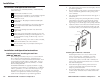
Installation and Operation, cont’d 8. Front and rear panel features Set the rear panel peaking jumpers, and cable and test the buffer before fastening the buffer into the wall box. The jumpers and cables will be inaccessible after installation. See “Rear panel/circuit board features and jumpers” and “Cabling” in this chapter for details. Mounting the RGB 340 Front panel features and operation 1 1 H. SHIFT V.
Installation and Operation, cont’d 5 buffer to the display/projector. If the request is granted, the buffer’s Show Me/Select button (RGB 324) or the LED next to the Show Me/Select button (RGB 340) lights. The LED corresponding to the input from this buffer will light on the RGB 320. Adjust knob (RGB 324, RGB 340) — Turning this knob adjusts the horizontal centering, vertical centering, video level, or audio level of the active buffer.
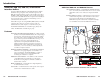
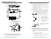
Installation and Operation, cont’d Rear panel/circuit board features and jumpers 2 OUTPUT L AUDIO R R G B H COM/PWR Audio output and communications/power connector — Wire this 3.5 mm 10-pole captive screw connector as shown in “Connecting the buffer to the RGB 320 with installation cable” in this chapter (pages 2-11 to 2-14). V A B C D E The left half of this connector is for audio output to the RGB 320. The right half of this connector serves as a port for power and buffer-RGB 320 communications.
Installation and Operation, cont’d 4. 5. Remove the Adjust knob. You may need a very small diameter Allen wrench to loosen the nut that holds it in place. Metal Wall Box Slide the top part of the enclosure slightly forward, then upward to remove the cover. The circuit board remains in the bottom portion of the enclosure.
Installation and Operation, cont’d 2. Determine what colors of each conductor type will be used for which signal, or use the examples provided in this manual. 3. Strip 7” to 8” (18 cm to 20 cm) of the outer jacket from the end of the cable. 4. Use a pointed tool to separate the braided wire shield surrounding the cable. Pull the ends of the braid away from the cable, twist the braid wires together, and clamp them to the electrical box (if used). See “Connecting shields”, page 2-10.
Installation and Operation, cont’d Black Mini-Coax (H/HV) Black Mini-Coax (H/HV) R H/HV R H/HV G V G V R H/HV R H/HV G V G V Anaheim, CA Anaheim, CA R COM / PWR A B C D E A B C D E R COM / PWR A B C D E L 2 R COM / PWR A B C D E RGB 320 Rear Panel White Black Shields Red Black Black Orange Brown Violet Grey White Black Shields Red Black Black Orange Brown Violet Grey RGB 320 Rear Panel 1 L Red Mini-Coax (R) 2 Red Mini-Coax (R) L COM / PWR Yellow Mini-Coax (V) R Gr
Installation and Operation, cont’d Pre-installation testing/troubleshooting Before installing a buffer into the wall or furniture, test the system to make sure that the connections and settings are correct. 1. With the power disconnected from the RGB 320, connect the cables between the buffer and the RGB 320 as described in “Preparing and terminating the cable” in this chapter. 2. Apply power to the RGB 320. The power LED on the buffer will light steadily to indicate that the buffer is receiving power.
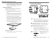
Installation and Operation, cont’d RGB 324/326/340 Wall Stud Screws or Nails A Cable Clamp AC Installation Cable TIV E UT INP 75 HIG H Ex Z 26 B3 RG Ohm AU DIO n tro RGB 326 Mounting the buffer to the wall box 5. Reconnect the input cables to the buffer’s front panel connectors. 6. Reconnect the power cables and restore power to the equipment.
Specifications, Accessories & Part Numbers, cont’d Specifications Video Gain ............................................... Unity (0.7V p-p), (0.8V p-p) 15% with 3dB peaking, (0.9V p-p) 30% with 6dB peaking Bandwidth .................................... 300 MHz (-3dB) Video input Number/signal type ................... 1 analog RGBHV, RGBS, RGsB, RsGsBs Connectors .................................... 1 9-pin D male analog for MBC/LBC cable Nominal level(s) .......................... Analog ....... 0.
Specifications, Accessories & Part Numbers, cont’d Vibration ....................................... NSTA 1A in carton (National Safe Transit Association) Approvals ..................................... UL, CE, FCC Class A MTBF ............................................. 30,000 hours Warranty ....................................... 2 years parts and labor Specifications are subject to change without notice.
B-2 RGB 324/326/340 • Dimensions and Template HAND SAND TO 0.06" RADIUS AROUND TOP EDGES. DETAIL C 6 REQ'D ø.160 THRU, WITH C'SINK ø.290 x 82˚ ON NEAR SIDE. (4 PLCS CODED A) 4 REQ'D DETAIL D 0 DATUM ø.166 THRU, TYP. (4 PLACES CODED C) 0 DATUM ø.166 THRU, TYP. (6 PLACES CODED C) NOTE: DRAWING IS NOT TO SCALE ø.160 THRU, WITH C'SINK ø.290 x 82˚ ON NEAR SIDE. (4 PLCS CODED A) NOTE: DRAWING NOT TO SCALE PEM STANDOFF BSOS-440-22 DETAIL C DETAIL A ø.120 THRU, WITH ø.250 C' X .
Dimensions and Template, cont’d RGB 324/RGB 326 wall box dimensions Below is a diagram of the dimensions of the electrical wall box that is shipped with an RGB 324 or RGB 326. If you use a different wall box, use its measurements when planning the installation. DETAIL D DETAIL C DETAIL B DETAIL A ROTATED 180˚ (2 PLCS) R .132 (4 CORNERS) RGB 340 dimensions Outside width of box = 3.75" (9.5 cm) H. SHIFT Height of inside opening = 3.0" (7.6 cm) Height of box = 3.75" (9.5 cm) ø.
Dimensions and Template, cont’d RGB 324/RGB 326 Cut-out Template Use the full-size template below as a guide to mark and cut the hole in the wall or furniture through which the buffer will be installed. The template includes the recommended 0.1” (0.25 cm) clearance on all sides of the electrical wall box to allow room for the raised areas surrounding the knockouts. See chapter 2 for details on installing the buffers. The light gray area represents the layout of the electrical box (3.75"H x 3.
Dimensions and Template, cont’d B-8 RGB 324/326/340 • Dimensions and Template