User’s Manual Audio/Video Switchers SW6 AV MX SW6 AV MX AS SW6 CV MX SW6 CV MX AS SW6 SA MX SW6 SV MX SW6 SV MX AS SW6 SV A MX SW6 SV A MX Auto www.extron.com Extron Electronics, USA Extron Electronics, Europe Extron Electronics, Asia Extron Electronics, Japan 1230 South Lewis Street Anaheim, CA 92805 USA 714.491.1500 Fax 714.491.1517 Beeldschermweg 6C 3821 AH Amersfoort The Netherlands +31.33.453.4040 Fax +31.33.453.4050 135 Joo Seng Road, #04-01 PM Industrial Building Singapore 368363 +65.6383.
Precautions Safety Instructions • English This symbol is intended to alert the user of important operating and maintenance (servicing) instructions in the literature provided with the equipment. This symbol is intended to alert the user of the presence of uninsulated dangerous voltage within the product's enclosure that may present a risk of electric shock. Caution Read Instructions • Read and understand all safety and operating instructions before using the equipment.
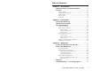
Table of Contents Chapter 1 • Introduction .......................................................... 1-1 About the Audio and Video Switchers ...................... 1-2 Features ...................................................................................... 1-2 S-video models ....................................................................... 1-3 Composite video models ....................................................... 1-3 Audio models ........................................................
Table of Contents, cont’d Chapter 4 • Remote Control .................................................. 4-1 Simple Instruction Set Control ....................................... 4-2 Host-to-interface communications ....................................... 4-2 Switcher-initiated messages .................................................. 4-3 Error responses ...................................................................... 4-3 Timeout ......................................................................
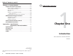
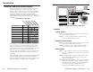
Introduction, cont’d Introduction About the Audio and Video Switchers The Extron SW family of audio/video switchers are 6-input, 2-output composite video, S-video, and/or stereo audio switchers. The AS and Auto versions are functionally identical, but also include an auto-sync detect mode. Auto-sync detect mode, when enabled, automatically selects the highest numbered input with a video signal available. The following table identifies the models and their video, audio, and auto-sync capabilities.
Introduction, cont’d Auto models Auto-sync detect — Auto or AS models continuously monitor all inputs and automatically switch to the highestnumbered input with video sync pulses present. If video is absent from all inputs, no input is selected. The auto version can operate in either normal (manual switch) or auto-switch mode. All models Front panel control — The operator can select the input and set the audio gain and attenuation for each input using the front panel buttons.
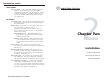
Installation, cont’d Installation Installation Overview Rear Panel Cabling To install and set up an Extron A/V switcher for operation, follow these steps: 1 Turn off all of the equipment that will be connected to the switcher. 2 Mount the switcher. See Mounting the switcher in this chapter. 3 Attach the cables. See Rear Panel Cabling in this chapter. 4 Connect power cords and turn on the display devices and the input devices. 5 Set the audio gain and attenuation.
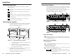
Installation, cont’d Audio models 3 Signal output connections Connections for balanced and unbalanced audio inputs — Each input has a 3.5 mm, 5-pole captive screw connector for balanced or unbalanced stereo audio input. Connectors are included with each A/V switcher, but you must supply the audio cable. See figure 2-4 to wire a connector for the appropriate input type and impedance level. High impedance is generally over 800 ohms.
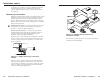
Installation, cont’d See chapter 4, RS-232/Remote Control for definitions of the SIS commands, details on how to install and use the control software, and information on how to make a remote contact closure device. VCR Monitor External sync connection SW6 SV A MX OCK IN GENL B/B-Y 32 RS-2 G/Y R/R-Y S V O VIDE OU T 0.3A 0V IN MAC I N P U T S PAL OUT 75 OHM When the switching between inputs, the resulting image change should be seamless, or clean.
Installation, cont’d Audio/Video Switchers 3 Chapter Three Operation Front Panel Controls and Indicators Front Panel Operations Memory Troubleshooting — If no image appears 2-8 Audio/Video Switchers • Installation
Operation, cont’d Operation As a secondary function on auto-sync detect models, the button is used with the input 1 button to select normal mode. See Normal and auto sync mode in this chapter. Front Panel Controls and Indicators Figure 3-1 shows the controls and indicators on the front panel of the SW6 CV MX switcher, which is video only and has no auto-sync detect capabilities. Figure 3-2 shows the front panel of the SW6 SV A MX Auto switcher, which has audio and autosync capabilities.
Operation, cont’d output video using each device’s own operating instructions. Select an input. The image should appear on the screen. When changing mode, if the input 1/Mode button is released too soon (before the input 2 or 3 LED begins to blink), input 1 may be selected. Selecting an input To select an input using the front panel buttons, press and release the button for the desired input (auto-sync detect models must be in normal mode). The LED for the selected input lights.
Operation, cont’d 1. There is one audio level setting per input. The setting is shared by the left and right audio inputs. E D 2. The audio level settings are stored in non-volatile memory. When power is removed and restored, the audio level settings are retained. E D B1 Viewing and adjusting an audio level -1dB See figure 3-3 and figure 3-4 and the following steps for an example of viewing and adjusting the audio level on a switcher with audio.
Operation, cont’d Audio/Video Switchers 4 Chapter Four RS-232/Remote Control Simple Instruction Set Control Windows-Based Program Control Contact Closure Remote Control Infrared Remote Control 3-8 Audio/Video Switchers • Operation
RS-232/Remote Control, cont’d The A/V switchers’ rear panel Remote connectors (Figure 4-1) can be connected to the serial port output of a host device, such as a computer or control system, to an Extron IR 20 Universal SYS 4/8/10/AV remote control, or to a remote contact closure device. Other than the IR 20, remote communications with the switcher are via Extron’s Simple Instruction Set, Extron’s Windows-based control program, or pin-programmed in the case of a contact closure device.
4-4 X1 = Input number 0 through 6 (0 = muted output X2 = Gain/attenuation value 16 steps ±1dB per step X3 = Gain/attenuation value Numeric dB value, –15 to +9 X4 = Switch mode 1 = normal (manual) mode 2 = auto-switch mode X5 = Software version x.
RS-232/Remote Control, cont’d Windows-Based Program Control The Universal Switcher Control Program, part #29-031-01, is compatible with Windows 3.1/3.
RS-232/Remote Control, cont’d Shorting the contact closure pin to override the front panel selection will work for all inputs on non autoswitching models. On auto-switching models, only the contact closure pins for inputs 2 through 6 can be shorted in this fashion. If pin 1 is connected to ground for an extended period on an auto-switch model, input 1 is not selected. Rather, the LEDs alternately display the previously selected input and blink the current front panel mode.
Specifications, cont’d Specifications Video Gain ............................................... Bandwidth .................................... Differential phase error .............. Differential gain error ................. Crosstalk ....................................... Switching speed ........................... Unity 30 MHz (-3dB) 0.01º, 4.43 to 30 MHz 0.03%, 4.43 to 30 MHz -70dB @ 3.58 MHz 160 nS (max.) Video input Number/signal type ................... 6 S-video ..................................
Accessories and Part Numbers, cont’d 0dBu = 0.775 volts (RMS). Included Parts Included parts Control/remote — switcher Switcher Serial control port ........................ Baud rate and protocol ............... Serial control pin configurations Contact closure ............................
Accessories and Part Numbers, cont’d S-video Cable SVHS 100’ (100 feet/30.4 meters) Super High Resolution Cable A-6 Part number 26-316-07 Part number SHR 1-3’ (3 feet/0.9 meter) 26-383-01 SHR 1-6’ (6 feet/1.8 meters) 26-383-12 SHR 1-12’ (12 feet/3.7 meters) 26-383-07 SHR 1-25’ (25 feet/7.6 meters) 26-383-04 SHR 1-50’HR (50 feet/15.2 meters) 26-383-05 SHR 1-75’HR (75 feet/22.9 meters) 26-383-06 SHR 1-100’HR (100 feet/30.5 meters) 26-383-03 SHR 1-150’HR (150 feet/45.