User Guide XTP Extender XTP T UWP 202 Two Input XTP Transmitter – Decora® Wallplate 68-2033-01 Rev.
Safety Instructions Safety Instructions • English WARNING: This symbol, , when used on the product, is intended to alert the user of the presence of uninsulated dangerous voltage within the product’s enclosure that may present a risk of electric shock. ATTENTION: This symbol, , when used on the product, is intended to alert the user of important operating and maintenance (servicing) instructions in the literature provided with the equipment.
FCC Class A Notice This equipment has been tested and found to comply with the limits for a Class A digital device, pursuant to part 15 of the FCC rules. The Class A limits provide reasonable protection against harmful interference when the equipment is operated in a commercial environment. This equipment generates, uses, and can radiate radio frequency energy and, if not installed and used in accordance with the instruction manual, may cause harmful interference to radio communications.
Conventions Used in this Guide Notifications The following notifications are used in this guide: WARNING: A warning indicates a situation that has the potential to result in death or severe injury. CAUTION: A caution indicates a situation that may result in minor injury. ATTENTION: Attention indicates a situation that may damage or destroy the product or associated equipment. NOTE: A note draws attention to important information. TIP: A tip provides a suggestion to make working with the application easier.
Contents Introduction..................................................... 1 SIS Configuration and Control...................... 18 About this Guide.................................................. 1 About the XTP T UWP 202.................................. 1 Key Features....................................................... 2 Host Device Connection.................................... 18 SIS Programming Guide.................................... 18 Host-to-Device and Device-to-Host Communication.......
XTP T UWP 202 Wallplate Transmitter • Contents vi
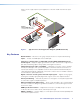
Introduction This section contains general information about this guide and the Extron XTP T UWP 202 Wallplate Transmitter, and selected device features. Topics in this section include: • About this Guide • About the XTP T UWP 202 • Key Features About this Guide This guide contains installation, operation, and control procedures, and reference information for the XTP T UWP 202 Wallplate Transmitter.
Figure 1 shows a typical point-to-point application of the XTP T UWP 202 with two input sources.
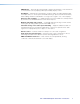
EDID Minder — Automatically manages EDID communication between connected devices to ensure that all sources properly power up and reliably display content. Key Minder — Authenticates and maintains continuous HDCP encryption between input and output devices to ensure quick and reliable switching in professional AV environments, while enabling simultaneous distribution of a single source signal to one or more displays.
Installation and Operation This section contains information for mounting, connecting, and wiring the XTP T UWP 202. Topics in this section include: • Installation Overview • Installing the Metal Junction Box or Mud Ring • Rear and Side Panel Connectors • Mounting the XTP T UWP 202 • Front Panel Connectors • Making Connections • Operation Installation Overview The XTP T UWP 202 can be installed into the provided mud ring or an UL Listed metal electrical junction box.
4. Route and connect cables to the rear and side panel connectors (see Rear and Side Panel Connectors on page 7). 5. Mount the XTP T UWP 202 to the mud ring or metal junction box (see Mounting the XTP T UPW 202 on page 9). 6. Connect inputs to the front panel connectors (see Front Panel Connections on page 10). 7. Supply power to all connected devices. Installing the Metal Junction Box or Mud Ring Cutting an Opening in the Mounting Surface 1.
Installing the Mud Ring Backing Clip Mounting Screw Rotate the backing clip out of the way to insert the mud ring into the wall. Figure 2. Installing the Mud Ring with Backing Clips 1. Place 1.25 inches (3.18 cm) long or 0.75 inch (1.90 cm) #6-32 thread machine screws through the large holes in the two corners of the mounting bracket. Use the shortest possible screw needed. 2. Loosely fasten the mounting backing clip on the end of each screw. 3.
Installing a UL Listed Metal Junction Box Metal junction boxes may differ slightly from model to model. Check with the manufacturer for specific installation instructions. Use metal junction boxes only. ATTENTION: Wall Stud Screws or Nails Wall opening is flush with edge of box. Cable Clamp Signal Output Cable Figure 4. Installing a Metal Junction Box 1. Insert the metal junction box into the hole in the wall. 2. Secure it to the stud using two screws or nails, as appropriate.
A XTP output connector — Connect a twisted pair cable to the RJ-45 connector labeled XTP Out on the XTP T UWP 202 and the XTP input port on another XTP device to pass all signals (see TP Cable Termination and Recommendations on page 12).
Mounting the XTP T UWP 202 NOTE: If desired, connect a host device to the front panel Config port (see figure 8, E) before mounting to configure the transmitter (see SIS Configuration and Control on page 18 or XTP System Configuration Software on page 23). Disconnect the host device after configuration is complete. 1 AU IN DIO T CP R HD PW MI HD MI HD IN VGA SE RE DIO AU IP CL 2 A IN VG TO AU CH IT SW IG NF CO LAN 3 XTP T UWP 202 Decora Faceplate Figure 6.
Front Panel Connectors PWR HDCP HDMI VGA RESET HDMI IN AUDIO IN B AUDIO CLIP A AUTO SWITCH VGA IN C E LAN Audio Plugs.eps CONFIG D Tip (+) A B C HDMI input connector A HDMI input connector — Connect a digital video source device to the HDMI Tip (+) connector. It can accept HDMI, DVI (with an appropriate adaptor), or dual mode Ring (-) DisplayPort video sources.
Selected Video Input HDMI Embedded Audio Present Analog Audio Present Audio Sent Over XTP VGA N/A Yes Analog audio VGA N/A No No audio HDMI Yes No HDMI embedded audio HDMI Yes Yes HDMI embedded audio HDMI No Yes Analog audio HDMI No No No audio C Analog video input connector — Connect a video source to the female 15-pin HD connector. It accepts RGBHV video signals.
TP Cable Termination and Recommendations Use the following pin configurations for twisted pair cables.
RS-232 and IR Over XTP Communication The RS-232 and IR Over XTP connector is for pass-through transmission of serial signals, such as projector control signals, and infrared data. To pass bidirectional serial command signals between XTP-compatible devices, connect a control device to the three leftmost poles (Tx, Rx, and G) of the 5-pole captive screw connector. To transmit and receive IR signals, connect a control device to the three rightmost poles (G, Tx, and Rx). The ground (G) pole is shared.
Power Connection Apply power to the transmitter locally with the provided power supply or remotely with a power injector or an XTP matrix switcher. ATTENTION: XTP remote power is intended for indoor use only. No part of the network that uses XTP remote power should be routed outdoors. Local power 3/16” (5 mm) Max. SECTION A–A Smooth Ridges A A Power Supply Output Cord Figure 13. Power Wiring The XTP T UWP 202 can be connected to a local power supply. WARNING: Electric shock hazard.
Remote power The XTP T UWP 202 can be powered remotely through an XTP Power Injector or through an XTP matrix switcher. ATTENTION: XTP remote power is intended for indoor use only. No part of the network that uses XTP remote power should be routed outdoors.
Operation After all transmitters, all receivers, and their connected devices are powered up, the system is fully operational. If any problems are encountered, verify that the cables are routed and connected properly. If problems persist, call the Extron S3 Sales & Technical Support Hotline. See the contact numbers on the last page of this guide for the nearest Extron office. Indicators A PWR HDCP HDMI VGA HDMI IN RESET AUDIO IN AUDIO CLIP AUTO SWITCH VGA IN B C LAN CONFIG Figure 15.
Reset Modes PWR HDCP HDMI VGA RESET HDMI IN AUDIO IN AUDIO CLIP AUTO SWITCH A VGA IN LAN CONFIG Figure 16. Reset Button (LAN Model Shown without the Decora Faceplate) Use the recessed Reset button on the front panel of the transmitter to return the device to default settings or to restore factory-shipped firmware. To access the Reset button, the faceplate may need to be removed (see figure 16, A).
SIS Configuration and Control The XTP T UWP 202 can be configured and controlled using Extron Simple Instruction Set (SIS) commands or the XTP System Configuration Software (see XTP System Configuration Software on page 23). This section contains basic SIS communication details and SIS commands and responses when connected directly to the XTP T UWP 202.
Error Responses When the XTP T UWP 202 receives an SIS command and determines that it is valid, it performs the command and sends the corresponding response to the host device. If the command is determined invalid or contains invalid parameters, the switcher returns an error response to the host.
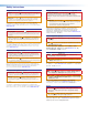
Command and Response Tables for SIS Commands Command ASCII Command Response Additional Description Select input X! ! In X!] Select input X!. View the selected input ! In X!] View the selected input. E 0AUSW} E 1AUSW} Ausw0 ] Switch inputs manually. Ausw1 ] When available, automatically switch to the HDMI input (default). E 2AUSW} Ausw2 ] When available, automatically switch to the VGA input. Ausw X#] View the auto switch mode.
Command ASCII Command (Host to Device) Response (Device to Host) Additional Description Black signal for audio only NOTE: The switcher uses a black signal to simulate a 720p or 1080p, 50 Hz or 60 Hz signal so audio can be passed without video. Enable black signal E B1AFMT} AfmtB X(] Disable black signal E B0AFMT} AfmtB X(] View black signal setting E BAFMT} AfmtB X(] Picture Adjustment Commands (Analog Only) Enable a black signal for audio only. Disable the black signal.
Command ASCII Command (Host to Device) Response (Device to Host) Additional Description EDID Commands NOTE: For EDID management, use the XTP System Configuration Software (see EDID Minder on page 34). Advanced Configuration Commands HDCP authorized device (HDMI input only) HDCP authorized device On E E1HDCP} HdcpE1 ] Designate the transmitter as an HDCP authorized device (default). HDCP authorized device Off E E0HDCP} HdcpE0 ] Do not designate the transmitter as an HDCP authorized device.
XTP System Configuration Software This section contains installation and configuration procedures for the XTP System Configuration Software for configuring and controlling the XTP T UWP 202. It can also be controlled with SIS commands (see SIS Configuration and Control on page 18).
Using the XTP System Configuration Software The XTP T UWP 202 can be controlled directly from the front panel Config port or remotely from an XTP matrix switcher. Connections When opening the XTP System Configuration Software, the Connections screen opens first. This screen is used to establish communication with an XTP device through USB connection (see Configuration port on page 11). Ensure the transmitter is connected and powered on before attempting to connect to it. Figure 19. Connections Screen 1.
Top Menu The top menu bar contains three menus for configuring software settings. File menu The File menu contains options for disconnecting from the transmitter and exiting the program. To access the menu, click the File menu. Figure 20. File Menu Disconnect This option disconnects the connected device from the XTP System Configuration Software. From the File menu, select Disconnect. The Connections screen opens.
Update Firmware This option uploads firmware from the host device to the connected device. NOTE: If necessary, download new firmware from the Extron website (see Downloading Firmware on page 38). 1. From the Tools menu, select Update Firmware. A dialog box opens to ask permission to disconnect from the device. Figure 22. Confirm Disconnect Dialog Box 2. Click the Yes button to disconnect from the device and continue with the firmware update process. The Update Firmware dialog box opens. Figure 23.
Help menu The Help menu contains a way to access XTP System Configuration Software information, a link to the help file, and a link to the Extron website. Figure 24. Help Menu NOTE: The Tutorial (System Configuration) option is not available when directly connected to the XTP T UWP 202. About the Software This option provides basic information about the XTP System Configuration Software, including version number and copyright information. Figure 25. About - XTP Dialog Box (Example) 1.
Device Settings The Device Settings screen allows a user to view and edit various device settings for the device directly connected to the PC running the XTP software. Click the Device Settings icon (see figure 26, 1) on the Global Navigation bar to open the Device Settings screen. Figure 26. Transmitter Device Settings Screen AV Controls panel The AV Controls panel, located on the left, is used to selection an input. 2 Input selection — Click an Input button to select an input.
Input/Output tab Click the Input/Output tab (see figure 27, 1) to open the Input/Output screen. It contains input information and options to apply automatic settings to individual inputs. Figure 27. Input/Output Tab 2 3 Input — Displays the input name. 4 Auto-Image — Attempts to size and center the input signal based on the aspect ratio setting. Auto-Image is applied whenever there is a change in the input sync.
Analog Video tab Click the Analog Video tab (see figure 28, 1) to open the Analog Video screen. It contains signal sampling, image shifting, and saving and recalling input preset options. Figure 28. Analog Video Tab Image Settings panel Signal sampling optimizes the input signal to the transmitter for the currently selected input.
Audio tab Click the Audio tab (see figure 29, 1) to open the Audio screen. It contains settings for audio input format and analog audio gain. Figure 29. Audio Tab Input format panel 2 Input format — From the Audio Format drop-down list, select the format for input 2. It can be Auto, HDMI, or Analog. 3 Analog audio gain — Click and drag the handle of the Gain slider, enter a value in the field, or click the Up or Down arrow to adjust the analog input gain.
General tab Click the General tab (see figure 30, 1) to open the General screen. It contains settings for auto switch mode and factory reset. Figure 30. General Tab Auto-input Switching panel 2 Auto-input Switching — Click the Enable Auto-Input Switching check box to enable auto switch mode. Two settings are available for this mode: Õ Click the Priority to highest active input number radio button to automatically switch to the highest numbered active input (HDMI).
Device Information panel The Device Information panel on the right side of the software screen displays device information and settings. General Information section 1 2 Model — Displays the device model. Firmware version — Displays the full firmware version. Signal Information section 3 Selected input — Displays the input number of the currently selected input (1 = VGA input and 2 = HDMI input). 4 Auto-input switching — Displays the On or Off status of auto switch mode.
EDID Minder Use the EDID Minder screen to assign unique EDID to the input or match current output resolutions to the input. Click the EDID Minder icon (see figure 31, 1) on the global navigation bar. The EDID Minder screen opens. The EDID Minder screen displays a table of EDID options and connected output devices, which are each represented by output display icons. • Factory default EDID options are displayed in blue. • Connected output resolutions and devices are displayed in green.
Import EDID 1. On the EDID Minder screen, click the Add EDID to Library button (see figure 31, 8). The Browse window opens. 2. Select the desired EDID file and click Open. The EDID appears in the Available EDID panel (see figure 31, 4). 3. Assign the EDID from the Available EDID panel to import the EDID setting to the device. Save output EDID 1. On the EDID Minder screen, right-click on the desired EDID setting in the Connected Outputs panel (see figure 31, 3). 2. Select the Save EDID to PC option.
Reference Information This section contains mounting information and instructions for updating firmware. Topics in this section include: • Updating Firmware with Firmware Loader • Mounting Template Updating Firmware with Firmware Loader To upload and update firmware for the XTP T UWP 202, download the new firmware to a connected computer and upload the firmware with the Firmware Loader utility. Downloading Extron Firmware Loader Figure 33. Locating Software on the Extron Website 1.
Figure 34. Navigating to Firmware Loader 3. Click the F link and navigate to Firmware Loader (see figure 34, 3). 4. Click the Download link on the right that corresponds with the program (see figure 34, 4). 5. Submit any required information to start the download. Note where the file is saved. Installing Firmware Loader 1. Once Firmware Loader has been downloaded, run the .exe file from the location where the file was saved. The installation wizard window opens. 2.
Downloading Firmware Figure 35. Downloading Firmware from the Extron Website 1. On the Extron website, click the Download tab (see figure 35, 1). 2. On the left sidebar, click the Firmware link (see figure 35, 2). 3. Navigate to the XTP T UWP 202. 4. Ensure the available firmware version is a later version than the current one on the device. NOTE: The firmware release notes are a PDF file that provides details about the changes between different firmware versions.
Installing Firmware with Firmware Loader Use the Firmware Loader utility to upload firmware to the transmitter when connected directly to the device. 1. Connect the host device to the front panel USB port. 2. Open Firmware Loader and establish a connection between the computer and the device. The Add Device... dialog box opens. Figure 36. Add Device... Dialog Box 3. From the Device Name drop-down list, select XTP T UWP 202. 4. From the Connection Method drop-down list, select the method of connection. 5.
Mounting Template Template for the 2-gang Figure 37 is a example of a mounting template for preparing mounting surfaces. It is not to mounting bracket full size. 4.26" (10.83 cm) 3.75" (9.53 cm) 4.28" (10.87 cm) 3.06" (7.78 cm) SURFACE CUT-OUT AREA FOR WALL MOUNT Recommended cut-out area for the installation surface. Top Panel Figure 37. Mounting Template for 2-gang Mud Rings NOTE: Measure template before cutting. Please measure thetheprinted template before cutting.
Extron Warranty Extron Electronics warrants this product against defects in materials and workmanship for a period of three years from the date of purchase.