User Guide Fiber Optic Extender FOX T UWP 302 Two Input Fiber Optic Transmitter 68-2092-01 Rev.
Safety Instructions • English WARNING: This symbol, , when used on the product, is intended to alert the user of the presence of uninsulated dangerous voltage within the product’s enclosure that may present a risk of electric shock. ATTENTION: This symbol, , when used on the product, is intended to alert the user of important operating and maintenance (servicing) instructions in the literature provided with the equipment.
FCC Class A Notice This equipment has been tested and found to comply with the limits for a Class A digital device, pursuant to part 15 of the FCC rules. The Class A limits provide reasonable protection against harmful interference when the equipment is operated in a commercial environment. This equipment generates, uses, and can radiate radio frequency energy and, if not installed and used in accordance with the instruction manual, may cause harmful interference to radio communications.
Conventions Used in this Guide Notifications The following notifications are used in this guide: WARNING: A warning indicates a situation that has the potential to result in death or severe injury. CAUTION: A caution indicates a situation that may result in minor injury. ATTENTION: Attention indicates a situation that may damage or destroy the product or associated equipment. NOTE: A note draws attention to important information.
Contents Introduction.................................................... 1 SIS Configuration and Control................... 13 About This Guide................................................. 1 About the FOX T UWP 302.................................. 1 System Compatibility....................................... 1 Cable Transmission Modes.............................. 1 Key Features....................................................... 2 Application Diagram............................................
FOX T UWP 302 Wallplate Transmitter • Contents v
Introduction This section describes general information about this guide and the FOX T UWP 302 Universal Wallplate Transmitter and selected device features. Topics in this section include: • About This Guide • About the FOX T UWP 302 • Key Features • Application Diagram About This Guide This guide describes installation, operation, and control procedures, and reference information for the FOX T UWP 302 Universal Wallplate Transmitter.
Key Features High reliability and maximum performance transmission over long distance fiber optic cabling — Transmits HDMI or analog video and stereo audio signals over very long distances using fiber optic cabling. Inputs — Include a female HDMI type A connector; 15-pin HD connector for RGBHV, RGBS, or HD component video; and a 3.5 mm stereo mini-jack for unbalanced stereo audio.
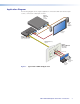
Application Diagram The following diagram shows a typical application of the FOX T UWP 302 with two input sources, connected to a fiber optic receiver. Extron XPA 1002 Power Amplifier Extron SI 28 02 A 10 XP G IN UT IR OUTP 2 SS 2W CLA 1 Surfacemount Speakers TE MO RE TS PU mA 50 UTE L/M 10V VO IN 2 1 BY ND STA L VE LE 2 1 1 z 60H A, 1.
Installation and Operation This section describes procedures to cable, connect, and manually operate the FOX T UWP 302. Topics in this section include: • Installation Overview • Rear Panel Features • Front Panel Features • Mounting and Making Connections • Operation Installation Overview Install the FOX T UWP 302 into an electrical UL Listed junction box. CAUTION: Risk of personal injury. Failure to check the items listed below may result in personal injury.
Rear Panel Features a Tx Rx Tx Rx G 1 2 b c Right Side a ALARM POWER 12V 0.6A MAX Rear FOX T UWP 302 Rear Connectors from the Side and Rear Panels Fiber connector — For one-way video, audio, and serial communication from the transmitter to a receiver, connect a fiber optic cable between the Tx port on the transmitter and the Rx port on a receiver.
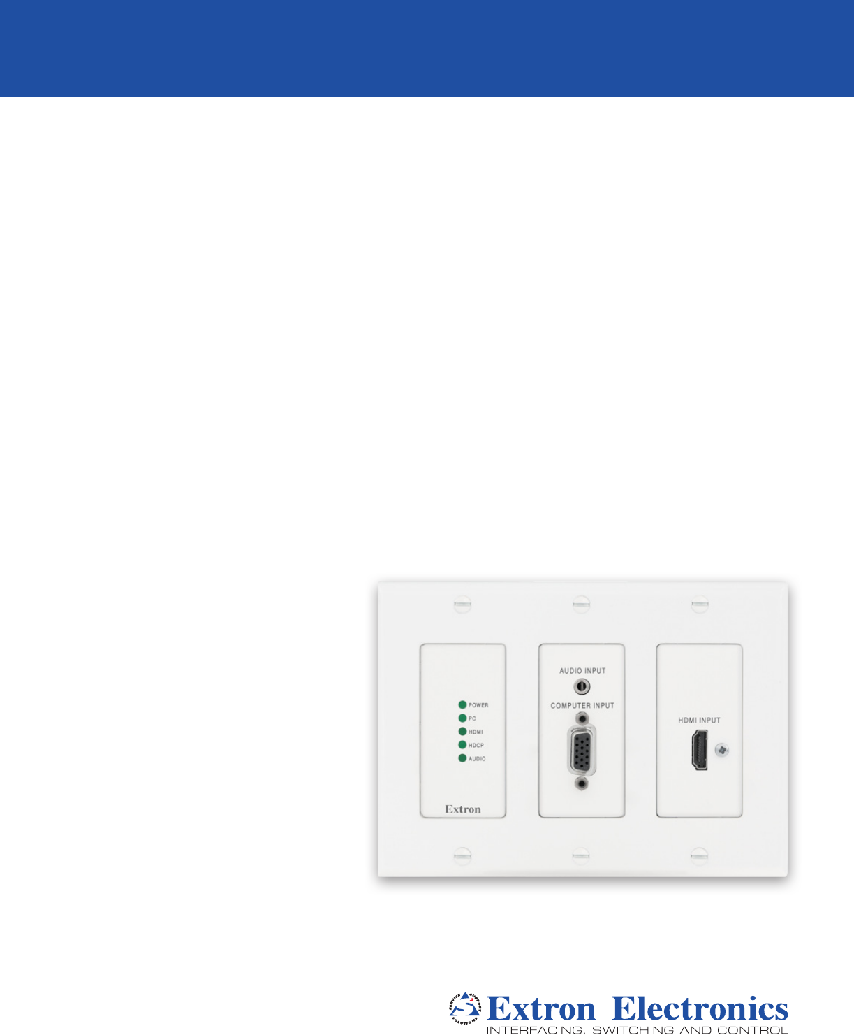
Front Panel Features Outside-the-Faceplate Features b AUDIO INPUT POWER a COMPUTER INPUT PC HDMI INPUT Audio Plugs.eps HDMI d HDCP AUDIO Tip (+) Figure 3. a Sleeve ( ) c FOX T UWP 302 Outside-the-Faceplate Features RCA Connector LED indicators Power LED — Lights when the device receives 12 V from an external power supply. PC LEDTip—(+)Lights when PC input is detected. Ring (-) HDMI LED — Lights when HDMI input is detected. HDCP LED — Lights if the HDMI input signal is HDCP encrypted.
Under-the-Faceplate Features LINK 2 LINK 1 e AUDIO INPUT COMPUTER INPUT POWER HDMI INPUT PC HDMI HDCP f RESET AUDIO g CONFIG Figure 5. FOX T UWP 302 Under-the-Faceplate Features e Link 1 and Link 2 LED indicators — Light when there is light present on the corresponding fiber optic port. f Reset button — Press the Reset button to return device settings or firmware to the factory default settings (see System Reset on page 12).
Mounting and Making Connections Mounting Before mounting an electrical UL Listed junction box, consider the mounting location and prepare the surface as necessary. Wall Stud Junction Box Screws or Nails Flush with Wall Surface b f e Mounting Screws (6 Plcs) Extron FOX T UWP 302 Universal Wallplate Transmitter Figure 6. Mounting the FOX T UWP 302 Into a Junction Box 1. Mount the junction box in the wall or floor, following the directions provided with the box. 2.
Connecting the HDMI Connector Use an Extron LockIt Lacing Bracket to secure an HDMI cable to each device as follows: d c a Figure 7. 3 b e Installing the LockIt Lacing Bracket 1. Plug the HDMI cable into the panel connection. 2. Loosen the HDMI connection mounting screw from the panel enough to allow the LockIt lacing bracket to be placed over it. The screw does not have to be removed. 3.
Wiring for Remote RS-232 and Alarm Communication The Remote RS-232 and Alarm connector is for RS-232 control (such as updating firmware, status queries, and various control functions) and the alarm feature. Wire the connector as shown in figure 8 below. REMOTE RS-232 Tx Rx G Tx Rx G RS-232 Device Figure 8. ALARM 1 2 1 2 Alarm Device Wiring the Remote RS-232 and Alarm Connector ATTENTION: The length of exposed wires is critical. The ideal length is 3/16 inch (5 mm).
Wiring the Power Supply Connect 12 VDC power supply to the 3.5 mm, 2-pole captive screw connector. 2-Pole Captive Screw Connector Tie Wrap 3/16” (5 mm) Max. SECTION A–A Smooth Ridges A A Power Supply Output Cord Figure 9. Power Connector Wiring CAUTION: Electric shock hazard. The two power cord wires must be kept separate while the power supply is plugged in. Remove power before wiring.
Operation After all devices are connected and powered, the system is fully operational. The FOX T UWP 302 can be configured through SIS commands (see Simple Instruction Set Control on page 13) or the FOX Extenders control program (see FOX Extenders Control Program on page 21). Initial Power Up Upon initial power up, all the front panel LEDs blink simultaneously. They blink once to indicate the device is a multimode device or twice to indicate the device is a singlemode device.
SIS Configuration and Control This section describes remote control of the FOX T UWP 302 through SIS commands and basic installation instructions for the FOX Extenders Control Program (see to the FOX Extenders Control Program Help File for configuration and control details). To enable serial control of the transmitter, use a computer running the HyperTerminal or Extron DataViewer utility, or a control system to enable serial control of the transmitter.
Error responses When the FOX T UWP 302 receives an SIS command and determines it is valid, it performs the command and sends the corresponding response to the host device. If the command is determined invalid or contains invalid parameters, the transmitter returns an error response to the host.
X2^ = EDID output resolution and refresh See the tables below.
Command and Response Tables for SIS Commands Command ASCII Command Response Additional Description Video input select X1! ! In X1! • ALL] Select input X1!. View video input ! X1!] View currently selected source. (Host to Device) (Device to Host) Input Switching Input selection NOTE: The FOX T UWP 302 saves the last input selection when cycling power. Auto switch mode E 0AUSW } E 1AUSW } Ausw0 ] Manual input switching only.
Command ASCII Command (Host to Device) Response Additional Description (Device to Host) Picture Adjustment (Analog Only) Pixel phase Set a pixel phase value E 1* X2@ PHAS} Phas X2@] Adjust the pixel phase to X2@ for input 1. Increment value E 1+PHAS} E 1-PHAS} E 1PHAS} Phas X2@] Increase the pixel phase. Phas X2@] Decrease the pixel phase. X2@] Show the pixel phase value for input 1. Set the total pixel value E 1* X2# TPIX} Tpix X2#] Set the total pixels to X2# for input 1.
Command ASCII Command Response Additional Description E 1LS} xxx.x,xxx.x ] Shows horizontal frequency in kHz and vertical frequency in Hz. 000.0,000.0 if no signal. Set input video format 1* X1% \ Typ1* X1%] Sets input 1 to format X1%. View input video format 1\ X1%] View video format of input 1. Disable Plus mode transmission 81*0# Plus0 ] Disable Plus mode transmission. Enable Plus mode transmission 81*1# Plus1] Enable Plus mode transmission (default).
Command ASCII Command (Host to Device) Response (Device to Host) Additional Description Device name NOTE: No blank or space characters are permitted. The first character must be a letter. The last character cannot be a minus or hyphen. Set unit name EX1^ CN} Set unit name to factory default E • CN} View unit name E CN} Ipn • X1^] Set device name. Ipn • X1&] Set device to default. X1^] View device name.
Command ASCII Command Response Additional Description 20S X!] Internal temperature in degrees Fahrenheit and Celsius. System reset (factory default) E ZXXX} Zpx] Resets unit to factory default (see System Reset on page 12). Reset audio gain and attenuation E ZA} Zpa] Reset audio gain and attenuation to default levels.
FOX Extenders Control Program The Extron FOX Extenders Control Program provides an alternate method to control and configure the FOX T UWP 302. The application provides controls to adjust device parameters that are specific to the basic and advanced setup of the transmitter. Users can also manage firmware and check for updates to the application.
Starting the Software Start the Extron FOX Extenders Control Program as follows: 1. Open the FOX Extenders Control Program. The Communication Setup window appears. Figure 11. Communication Setup Window Connection Methods 2. Select the desired connection method. • To connect the software to the device through the rear panel Remote RS-232 connector, click the RS232 tab and select the desired port from the Port drop-down list.
Figure 12. Main Screen The main screen consists of a top menu, Status panel, Input Selection panel, and Configuration panel. Top Menu The top menu consists of three menus for connection options, device information and configuration, and additional resources. File menu The File menu contains options for connecting and disconnecting the device and exiting the FOX Extenders Control Program. Figure 13. File Menu Options that appear gray are not available.
Connect The Connect option establishes communication with a device. This function re-establishes communication with the device if it times out or enables a connection to a new device. If a device is already connected, the Connect function is disabled until the device is disconnected or the connection times out. To re-establish the connection if communication is lost: 1. From the File menu, select Connect. Alternatively, click the icon.
Unit Info The Unit Info option opens a dialog box with information about the connected device. Figure 15. Unit Info Dialog Box 1. From the Tools menu, select Unit Info. This opens a dialog box displaying information about the connected unit. The displayed information includes: • Model number of the device • Name of the device model • Description of the model • Firmware version currently found on the device • Firmware build • FPGA version 2.
Master System Reset — Resets all unit settings and user settings to factory defaults. From the Tools menu, locate the Reset submenu and select Master System Reset. Figure 17. Unit System Dialog Box Audio Gain/Atten. Reset — Resets the level of audio gain and attenuation to factory defaults. From the Tools menu, locate the Reset submenu and select Audio Gain/Atten. Reset. Figure 18. Audio Gain and Attenuation Reset Dialog Box Presets Reset — Is not available for the FOX T UWP 302.
5. Click the Begin button. This uploads the new firmware onto the connected device. The Progress field for the selected device shows the progress of the upload. After the upload is complete, this field is blue and shows 100%. 6. Exit Firmware Loader. 7. From the File menu of the FOX Extenders Control Program, select Connect to re-establish communication with the device. 8. Re-enter the connection information in the Connect dialog box to re-establish communication with the device.
Help Menu The Help menu contains options for additional information and reference material, checking for updates to the FOX Extenders Control Program, and software information. Figure 20. Help Menu Contents The Contents option launches the FOX Extenders Control Program help file. Open the help file in one of the following ways: • From the Help menu, select Contents. • Press on your keyboard. • Click the icon to launch the help file.
About... This option opens a dialog box displaying information about the FOX Extenders Control Program. 1. From the Help menu, select About. This opens a dialog box displaying information about the FOX Extenders Control Program. The displayed information includes: • Name of the application • Currently installed software version • Software part number • Copyright • Application description Figure 21. About FOX Extenders Control Program Dialog Box 2.
Main Screen The Main Screen contains status information, input selection, and configuration options. Figure 22. Main Screen NOTE: The main screen may appear different from the image above depending on what is connected. Functions which are not applicable are disabled. Status panel Figure 23. Status Panel The Status panel of the screen provides visual indications of the connection status and the names of the connected units.
Video Indicator — Displays green when the transmitter detects an active signal on the VGA input. Audio Indicator — Displays green when the device detects audio with the selected input. If the selected input has an analog audio signal above -44 dBV, the indicator turns green immediately, but turns gray after the audio signal level drops below the threshold continuously for 10 seconds.
VGA Video Adjustment panel The VGA Video Adjustment panel of the Control tab adjusts the following video parameters on the analog input: horizontal start, pixel phase, and total pixels. Figure 26. VGA Video Adjustment Panel Horizontal Start — Defines the number of pixels in the blanking area to the left of the active area. In the Horizontal Start panel of the VGA Video Adjustment panel, click the Left or Right arrows, or click and drag the slider to adjust the setting to the desired value.
Audio Adjustment panel The Audio Adjustment panel of the Control tab adjusts the gain and attenuation of analog input audio. Audio Gain and Attenuation — Adjusts the analog input audio gain or attenuation value. This ranges from -18.0 dB to +10.0 dB in 1.0 dB increments. In the Audio Gain/Atten. panel, click and drag the slider to the desired level. The current value is displayed in a field below the slider control. Audio Output Level — Is not available for the FOX T UWP 302.
Plus Mode Transmission panel Plus mode can support rates up to 1920x1200 @ 60Hz, with embedded audio, and is HDCP compliant. Non-Plus mode supports rates up to 1600x1200 and 1080p, is HDCP compliant, and does not contain embedded audio (analog audio is still supported). In the Plus Mode Transmission panel, click the Enabled radio button to enable Plus mode. To disable Plus mode, click the Disabled radio button. NOTE: Default setting: Plus Mode is Enabled.
Advanced Configuration panel NOTE: This setting is not available for the FOX T UWP 302. EDID Configuration Tab EDID is a data structure used to communicate video display information, including native resolution and vertical refresh rate requirements, to a source device. The source device then outputs the optimal video format for the display based on the provided EDID data, ensuring proper video image quality. To access EDID options, click the EDID Configuration tab. Figure 30.
Import EDID panel EDID files can be imported to the FOX T UWP 302 and saved in a table on the device. NOTE: When an EDID file is imported to a user assigned input location, the EDID is automatically assigned to the selected user input. Figure 32. Import EDID Panel 1. In the Import EDID panel, from the drop-down list, select the desired input. Figure 33. Import EDID Options 2. Click on the Browse button to locate and select the desired EDID file on the connected PC. The Open dialog box opens. Figure 34.
Export EDID panel EDID files on the FOX T UWP 302 can be exported to the connected PC. To open and view them, use the Extron EDID Manager software, available at www.extron.com. The EDID Manager software aids in troubleshooting any EDID related issues that may occur during configuration or operation of an AV system. Figure 35. Export EDID Panel 1. In the Export EDID panel, select the desired EDID to export from the drop-down list. 2. Click the Export button. The Save As dialog box opens. 3.
Reference Information This section describes basic installation information of the Extron Firmware Loader program to upload firmware. Topics in this section include: • Firmware Loader • Firmware Updates Firmware Loader To upload and update firmware for the FOX T UWP 302, download the new firmware to a connected computer and upload the firmware with the Firmware Loader utility or the FOX Extenders Control Program (see to the FOX Extenders Control Program Help File).
Installing Firmware Loader 1. Once Firmware Loader has been downloaded, run the .exe file from the save location. The installation wizard window opens. 2. Click the Next button to continue through the installation process, filling out necessary information and specifying custom settings on each prompt. Firmware Updates Downloading Firmware Figure 37. Downloading Firmware from the Extron Website 1. On the Extron website, www.extron.com, click the Download tab. 2.
Installing Firmware with Firmware Loader 1. Open Firmware Loader and establish a connection between the computer and the device. The Add Device... window opens. Figure 38. Add Device... Window 2. Select FOX T UWP 302 from the Device Name drop-down list. 3. Select the method of connection from the Connection Method drop-down list. 4. Depending on the connection method, additional options appear. Make the appropriate selections for the current connection method. 5. Click the Connect button. 6.
Extron Warranty Extron Electronics warrants this product against defects in materials and workmanship for a period of three years from the date of purchase.