
User Guide


Table Of Contents
- Front Cover
- Safety Information
- FCC Class
- FDA/IEC 60825-1 Requirements
- Conventions Used in this Guide
- Specifications Availability
- Contents
- Introduction
- Installation and Operation
- SIS Configuration and Control
- FOX Extenders Control Program
- Reference Information
- Extron Warranty
Rear Panel Features
Tx
Rx
Rx
Tx
1
2
G
+
REMOTE
RS-232
ALARM
POWER
12V
0.6A MAX
-
RearRight Side
a
b
c
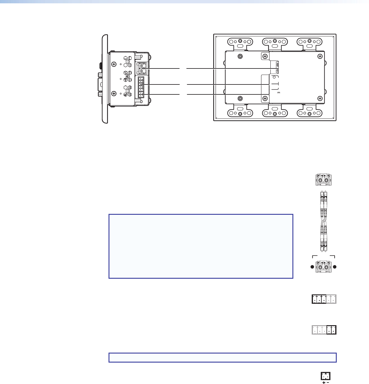
Figure 2. FOX T UWP 302 Rear Connectors from the Side and Rear Panels
a
Fiber connector — For one-way video, audio, and serial
communication from the transmitter to a receiver, connect a fiber optic
cable between the Tx port on the transmitter and the Rx port on a
receiver.
To return serial data from a receiver to the transmitter (such as
responses from a controlled device) or for HDCP-compliance, connect a
fiber optic cable between the Rx port on the transmitter and the Tx port
on the receiver (see Wiring for Fiber Communication on page 9).
NOTES:
• Ensure the proper fiber optic cable is used. Typically,
singlemode fiber optic cable has a yellow jacket and multimode
fiber optic cable has an orange or aqua jacket.
• Only one fiber optic cable, transmitter-Tx-to-receiver-Rx,
is required for video, audio, and serial command transmission,
but the HDMI signal output on the receiver will not be
HDCP-compliant.
b
Remote RS-232 port — For serial RS-232 control, connect a host device
to the transmitter via the leftmost poles (Tx, Rx, and G) of this 5-pole
captive screw connector (see Wiring for Remote RS-232 and Alarm
Communication on page 10 for wiring configuration).
Alarm output port — For remote monitoring of the status of fiber optic
link 2, connect a custom or furnished monitoring device to the transmitter
via the rightmost poles (1 and 2) of this 5-pole captive screw connector (see
Wiring for Remote RS-232 and Alarm Communication on page 10).
NOTE: Pins 1 and 2 short when link 2 does not detect any connection.
c
Power connector — Connect the provided external 12 VDC power supply
to this 3.5 mm, 2-pole captive screw connector (see Wiring the Power
Supply on page 11).
Transmitter
to
Receiver
OPTICAL
Rx
Tx
LINK
LINK
OPTICAL
Rx
Tx
Tx Rx 1 2G
Tx Rx G 1 2
FOX T UWP 302 Wallplate Transmitter • Installation and Operation 5