
User Guide


Table Of Contents
- Front Cover
- Safety Information
- FCC Class
- FDA/IEC 60825-1 Requirements
- Conventions Used in this Guide
- Specifications Availability
- Contents
- Introduction
- Installation and Operation
- SIS Configuration and Control
- FOX Extenders Control Program
- Reference Information
- Extron Warranty
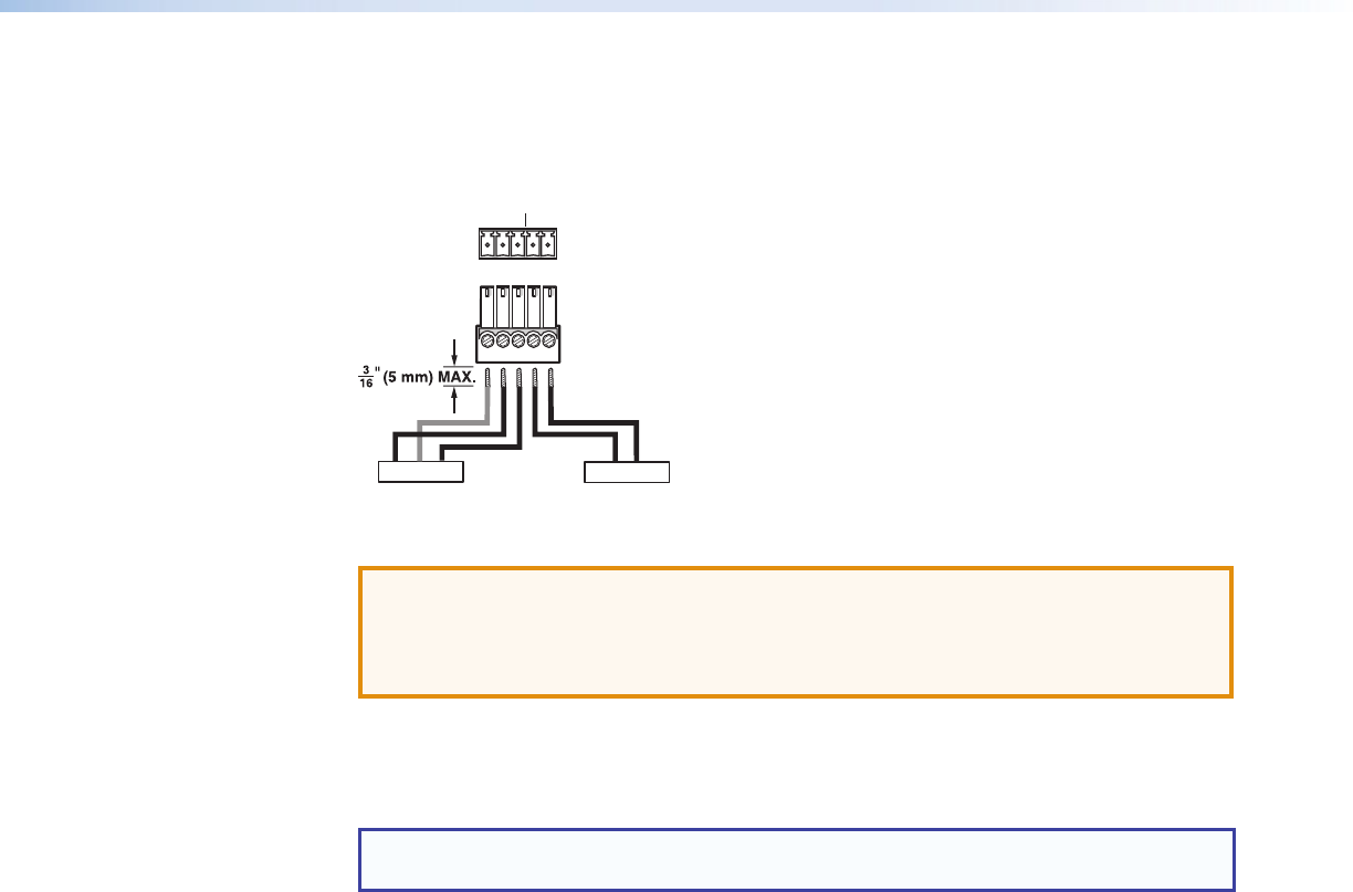
Wiring for Remote RS-232 and Alarm Communication
The Remote RS-232 and Alarm connector is for RS-232 control (such as updating firmware,
status queries, and various control functions) and the alarm feature. Wire the connector as
shown in figure 8 below.
RxTx
Alarm Device
RS-232 Device
G
REMOTE
RS-232 ALARM
Tx Rx G1 2
12
Figure 8. Wiring the Remote RS-232 and Alarm Connector
ATTENTION: The length of exposed wires is critical. The ideal length is
3/16 inch (5 mm).
• Longer bare wires can short together.
• Shorter wires are not as secure in the connectors and could be pulled out.
Cross the Tx and Rx lines once between the source and the target.
The alarm pins do not produce any discrete on or off or voltage signals. It is an internal relay
to connect or disconnect a custom alarm circuit.
NOTE: If power is lost or if link 2 optical light is disconnected, lost, or broken, alarm
pins 1 and 2 internally short.
FOX T UWP 302 Wallplate Transmitter • Installation and Operation 10