User’s Manual CAUTION Do not connect this device to a computer data or telecommunications network TP Transmitters and Receivers www.extron.com Extron Electronics, USA Extron Electronics, Europe Extron Electronics, Asia Extron Electronics, Japan 1230 South Lewis Street Anaheim, CA 92805 USA 714.491.1500 Fax 714.491.1517 Beeldschermweg 6C 3821 AH Amersfoort The Netherlands +31.33.453.4040 Fax +31.33.453.4050 135 Joo Seng Road, #04-01 PM Industrial Building Singapore 368363 +65.6383.4400 Fax +65.6383.
Precautions Safety Instructions • English This symbol is intended to alert the user of important operating and maintenance (servicing) instructions in the literature provided with the equipment. This symbol is intended to alert the user of the presence of uninsulated dangerous voltage within the product's enclosure that may present a risk of electric shock. Caution Read Instructions • Read and understand all safety and operating instructions before using the equipment.
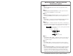
Quick Start Guide — IN1124/1128/1130 Transmission System Step 1 Turn the equipment off and disconnect the equipment from the power source. Step 2 If desired, rack mount the transmitter. Use the optional 1U rackmount shelf, part #IN9080, for rack mounting. Step 3 If desired, furniture mount the receiver. Use the optional mounting brackets, part #IN9089, to mount the receiver to any flat surface.
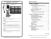
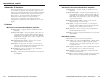
Quick Start Guide — IN1124/1128/1130 Transmission System, cont’d Table of Contents Chapter 1 • Introduction ....................................................... 1-1 Side Clip Down 12345678 Pin 12345678 About this Manual ............................................................ 1-2 About the Transmitter/Receiver System .................. 1-2 RJ-45 connector TIA/EIA T 568 A Wire color TIA/EIA T 568 B Wire color Signal 1 White-green White-orange Red/V. sync+ 2 Green Orange Red/V.
Table of Contents, cont’d IN1124/IN1128/IN1130 Transmission System 1 Chapter One Introduction Introduction Features ii IN1124/28/30 Transmission System • Table of Contents
Introduction, cont’d Introduction About this Manual This manual documents the installation, features, and operation of the Extron IN1124 and IN1128 TP twisted pair (TP) transmitters/distribution amplifiers (referred to in this manual as “transmitters” or “transmitter/DAs”) and the IN1130 TP receiver (referred to in this manual as a “receiver”).
Introduction, cont’d About the TP Receiver The Extron IN1130 TP receiver receives the transmission of one of transmitter’s proprietary video and audio signal over a TP cable. The receiver then decodes the received signal and buffers and distributes two identical video outputs on female 15-pin HD connectors. The receiver buffers and distributes two identical mono audio outputs on 3.5 mm mini jacks.
Introduction, cont’d IN1124/IN1128/IN1130 Transmission System 2 Chapter Two Installation and Operation Installation Overview Rack Mounting the Transmitter Furniture Mounting the Receiver Transmitter Cabling Transmitted Signal Cabling Receiver Cabling Operation Troubleshooting 1-6 IN1124/28/30 Transmission System • Introduction
Installation and Operation, Operation cont’d CAUTION Installation and service must be performed by authorized personnel only. Installation Overview To install and set up a TP transmitter/DA and the associated TP receiver(s) for operation, perform the following steps: 1 Disconnect power from all of the equipment, including the video source(s) (such as computers or HDTV set-top boxes), the transmitter, the receivers, and the output display(s). 2 If desired, mount the transmitter in a rack.
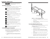
Installation and Operation, cont’d 10 4 5 Figure 2-2 — Under-desk or through-desk mounting 1 5 5 5 2 3 4 2 1 4 3 9 Figure 2-3 — Installation features, IN1124 Transmitter Cabling The IN1124 (figure 2-3) and the IN1128 (figure 2-4) accept and transmit computer video and PC audio. These transmitters can also accommodate component video, S-video, or composite video if input on the R, G, and B pins of the 15-pin HD connector using an Extron IN9045-L6 15HD male-to-5 BNC male, 6’cable.
Installation and Operation, cont’d Local Output connector — If desired, connect a local monitor video cable to this 15-pin HD female connector. 3 4 5 1 15 11 The sense lines on the Local Output connector are tied directly to the Input connector. standards. You can use either standard, but ensure you use the same standard on both ends of the cable. Side Clip Down 12345678 Local audio output connector — If desired, connect the PC audio output on this 3.5 mm, stereo jack to local powered speakers.
Installation and Operation, cont’d Extron skew compensation coax cables are available in lengths of 2 through 20 feet, see Appendix A for part numbers. The Microtest OMNI SCANNER 2 performs comprehensive certification testing to the proposed CAT 6 standards. Other manufacturers also make testing equipment. The tests include advanced diagnostics for troubleshooting the cause and location of many cable and termination problems.
Installation and Operation, cont’d Operation 9 IN1124/IN1128/IN1130 Transmission System Power — Plug the external 9V power supply into this power connector. The power supply is included with the unit. Plug the power supply into a 100 to 240VAC, 50 Hz or 60 Hz power source. Alternatively, an Extron P/S 100 Universal 12VDC Power Supply can power up to six transmitters or receivers using only one AC power connector. 10 Power LED — Lights to indicate that power is applied.
Reference Information Reference Information cont’d Video Number/signal type ................... 1, 4 or 8 sets of proprietary analog signals Connectors .................................... 1, 4 or 8 RJ-45 female Input impedance .......................... Output impedance ...................... Max. propagation delay .............. Max. rise/fall time ....................... 510 ohms 75 ohms 48 ns 3.5 ns Video input Number/signal type IN1124, IN1128 ..................
Reference Information cont’d General Included Parts Power ............................................. 100VAC to 240VAC, 50/60 Hz, 15 watts, external, autoswitchable IN1124, IN1128 ................. External 9VDC, 2.0A power supply. Product requires 1.6 A. IN1130 ............................... External 9VDC, 0.5A power supply. Product requires 0.45 A. Temperature/humidity ..............
Reference Information cont’d Skew-free A/V cable Suggested Accessories Accessory Part number P/S 100 Multiple output 12V power supply 60-357-01 1U rack-mount shelf (for IN1124, IN1128) IN9080 Rack-mount shelf blank panel (for IN1124, IN1128) IN9088B Mounting brackets (for IN1130) IN9089 Cables/Adapters Skew-Free A/V UTP cables are not recommended for Ethernet/LAN applications.
Reference Information cont’d RJ-45 connector CAT 6 jack (black) 10-463-10 CAT 6 jack (red) 10-463-11 CAT 6 jack (blue) 10-463-12 CAT 6 jack (orange) 10-463-13 CAT 6 jack (grey) 10-463-14 CAT 6 jack (white) 10-463-15 CAT 6 jack (ivory) 10-463-16 Skew compensation cable Part number 2’ skew cable (red, green, blue) 26-524, 525, 526-01 4’ skew cable (red, green, blue) 26-524, 525, 526-02 6’ skew cable (red, green, blue) 26-524, 525, 526-03 8’ skew cable (red, green, blue) 26-524, 525, 526