IN1404XT Video Scaler and Switcher 68-755-01 Rev.
Precautions Safety Instructions • English This symbol is intended to alert the user of important operating and maintenance (servicing) instructions in the literature provided with the equipment. This symbol is intended to alert the user of the presence of uninsulated dangerous voltage within the product's enclosure that may present a risk of electric shock. Warning Power sources • This equipment should be operated only from the power source indicated on the product.
Table of Contents Chapter 1 • Introduction ....................................................................................................... 1-1 About this Manual ............................................................................................................. 1-2 About the Scaler .................................................................................................................. 1-2 TP transmission .............................................................................
Table of Contents, cont’d Audio menu ......................................................................................................................... 3-9 Bass screen ................................................................................................................. 3-9 Treble screen ........................................................................................................... 3-10 Balance screen .............................................................................
Troubleshooting ................................................................................................................ 3-30 General checks ................................................................................................................. 3-30 Specific problems ............................................................................................................. 3-31 Chapter 4 • Programmer’s Guide ...............................................................................
Table of Contents, cont’d All trademarks mentioned in this manual are the properties of their respective owners. iv IN1404XT Video Scaler and Switcher • Table of Contents 68-755-01 Rev.
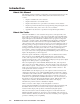
IN1404XT Video Scaler and Switcher 1 Chapter One Introduction About this Manual About the Scaler Features
Introduction, cont’d Introduction About this Manual This manual contains installation, configuration, and operating information for the Extron IN1404XT video scaler and switcher (referred to in this manual as the “scaler”). • Chapter 1 identifies the scaler’s features. • Chapter 2 details how to install the scaler. • Chapter 3 describes how to operate the scaler and use all of its features.
Extron CPM101 Connector Plate Extron VTR001 ER WER POW PO Twisted Pair Receiver r iver T ceive r CM Rece PUUT ive 01CMir Re INTP ce OOU T001 Pa CMir 01Pa ir Re VIDE O VTR0ed VT ist T0ed Pa VIDE VTist ed Tw Tw ist Tw Extron Skew-Free UTP Cable (up to 500') Projector Laptop Extron IN1404XT Laptop Video/RGB Scaler Video Camera VCR/DVD Figure 1-1— Typical IN1404XT Video Scaler and Switcher application TP transmission The TP output on the RJ-45 connector and an optional Extron VTR001CM receiver provid
Introduction, cont’d Features Inputs — Video inputs — The scaler switches among two fully-configurable RGB, HDTV component video, interlaced component video, progressive scan video, S-video, or composite video inputs on 5 BNC connectors (inputs 3 and 4); two S-video inputs on 4-pin mini-DIN connectors (S-video inputs 1 and 2 only); or composite video inputs on single BNC connectors (composite video inputs 1 and 2). Either S-video or composite video, but not both, can be connected to input 1 and to input 2.
and still content with different algorithms to yield high fidelity images that are free of visible scan lines. Inverse 3:2 pulldown detection for NTSC for film-originated video material — This advanced film mode processing feature helps maximize image detail and sharpness for video sources that originated from film. When film is converted to NTSC video, the film frame rate has to be matched to the video frame rate in a process called 3:2 pulldown.
Introduction, cont’d gamma, sharpness, image size, image position, and edge blanking. Individual image settings can be optimized and stored for each input. Each time an input is selected, all image settings stored for that input are automatically recalled. The on-screen menus also make it easy to verify and adjust advanced settings such as output signal resolution, refresh rate, sync format; the RS-232 control options; and the reset to factory defaults function.
IN1404XT Video Scaler and Switcher 2 Chapter Two Installation Installation Overview Mounting the Scaler Cabling and Rear Panel Views Configuration
Installation, cont’d Installation Installation Overview To install and set up an IN1404XT video scaler and switcher for operation, perform the following steps: n 1 Disconnect power from all of the equipment, including the video and audio source(s), and the devices that will receive the output video and audio signals. Ensure the power switch on the scaler is off. 2 Rack mount the scaler if desired. See Mounting the Scaler in this chapter. 3 Connect the video and audio input cables.
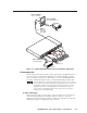
2. Attach one rack mount bracket to that side of the scaler with three screws removed in step 1. 3. Repeat steps 1 and 2 on the other side of the scaler. 4. Insert the scaler into the rack, align the holes in the mounting bracket with those of the rack. 5. Secure the scaler to the rack with machine screws. Cabling and Rear Panel Views All connectors are on the rear panel (figure 2-2).
Installation, cont’d Cr Y Cb R G/Gs B Cr Y Cb RGBHV RGBS RGsB, Component S-video Composite video R G/Gs B Cr (R-y) (Pr) Y Y Y Cb (B-Y) (Pb) R G/Gs B Cr (C) Y Cb R G/Gs B Cr Y (Vid) Cb R G/Gs B H/S V H/S V H/S V H/S V H/S V Figure 2-3 — Connections for various input video formats The audio bass, treble, and balance levels for each input can be individually set via the front panel or the RS-232 link.
8 RGB video transmission connector — Connect one end of a TP cable to this RJ-45 female connector. Connect the other end of the TP cable to an optional Extron VTR001CM or other compatible Extron TP receiver. See Optional Accessories, in Appendix A, Reference Information, for compatible TP receivers. The VTR001CM can receive RGBHV and RGSB signals from the scaler with no loss of image quality. The VTR001 CM can also receive RGsB signals from the scaler.
Installation, cont’d The Microtest OMNI SCANNER 2 performs comprehensive certification testing to the proposed CAT 6 standards. Other manufacturers also make testing equipment. The tests include advanced diagnostics for troubleshooting the cause and location of many cable and termination problems. For simple installation testing, the Microtest MICRO SCANNER PRO tests wire map and cable length, including individual cable pair length.
Extron CPM101 Connector Panel Extron VTR001 Twisted Pair Receiver r ive T ce CM 01 ir Re INPU O T0 Pa VT ed VIDE ist Tw CAT 5 UTP Cable IF cable measurement indicates that the pair with wires 1 and 2 is four feet shorter than the other signals... ... THEN insert a 15HD-to-BNC extension cable and a four-foot skew compensation cable to equalize UTP skew for red video.
Installation, cont’d 2-8 IN1404XT Video Scaler and Switcher • Installation
IN1404XT Video Scaler and Switcher 3 Chapter Three Operation Front Panel Controls and Indicators Front Panel Operations Optimizing the Video Optimizing the Audio Troubleshooting
Operation, cont’d Operation Front Panel Controls and Indicators All of the scaler’s controls are on the front panel (figure 3-1). Front panel LEDs provide graphic indication of some of the basic system functions. For more complex tasks, such as system configuration, the scaler has a menu system that is operated using the front panel buttons and displayed on the output monitors (figure 3-2).
If a different input is selected, see 1 , the switching action deselects the freeze function, the frozen image is lost, and the Freeze LED returns to its unlit state. Freeze has no affect on input 4 when it is passive (unscaled). Audio controls 4 Volume and buttons — The Volume buttons regulate the volume level of the selected audio input. Use the Volume buttons to increase and decrease the audio level for the current input.
Operation, cont’d 8 Enter button — The Enter button either activates a submenu or function in the IN1404XT menu system or saves a changed value. See Front Panel Operations in this chapter for details. The effects of all adjustments are visible on the screen or audible on the audio output, but they are temporary unless saved. The adjustments return to their previous settings when the adjustment screen exits by either a timeout or the operator pressing the Menu button.
15 sec. Menu No menu display Menu Menu or 15 sec. Ma i n Me n u V i deo Au d i o I n pu t Ou t p u t Ad v a n c e d 15 sec. V i de o B r i gh t nes s Co n t r a s t RGB Ga i n✫ Co l o r S a t u r a t i o n ✝ Hu e✝ Sh a r p n e s s✝ Gamma✝ No i s e F i l t e r✝ Comb / T r a p✝ Re s e t V i d e o Enter Menu Au d i o Menu Ou t pu t Re s o l u t i o n Re f r e s h Ra t e ❖ Se am l e s s Mo d e S i ze Po s i t i o n Sy n c Fo r m a t B l u e Sc r een R e s e t Ou t p u t 15 sec. Menu 15 sec.
Operation, cont’d 2. Press the Menu button. The on-screen Main Menu display appears on the connected monitors, overlaid on top of the output image. 3. Use the Menu and buttons to highlight the desired menu option on the Main menu (such as Video) and press the Enter button. The selected submenu appears on the connected monitors. 4. Use the Menu and buttons to highlight the desired option on the selected submenu (such as Brightness) and press the Enter button.
15 sec. 15 sec. 15 sec. 15 sec. Menu Enter (save) No menu display Menu Enter (save) B r i gh t nes s 128 Menu Enter (save) S h a r p n e s s✝ 3 Menu Enter (save) Co n t r a s t 128 Gamma✝ 10 15 sec.
Operation, cont’d RGB Gain screen The RGB gain adjustment is available for RGBHV, RGBS, RGsB, and progressive component video inputs only. The red, green, and blue gain screens display a status indicator that shows the input signal gain (contrast) setting for each individual color. Use the Menu and buttons to adjust each color’s gain control through a range of 0 to 255. The default setting is 128. An extra step is required to adjust the display, as follows: 1.
Gamma screen The gamma filters are available for interlaced component video, S-video, and composite video inputs only. The Gamma screen displays a status indicator that shows the selected gamma filter. The scaler has 30 programmed gamma filters that compensate for the non-linear response of many display devices. Use the Menu and buttons to step to loweror higher-numbered gamma curves through a range of 1 to 30. The default setting is 10, which selects a gamma correction curve of 1.0.
Operation, cont’d 15 sec. 15 sec. Menu Enter (save) No menu display Ba s s 16 Menu Enter (save) T r eb l e 16 15 sec. Enter Au d i o Ba s s T r eb l e Ba l a n c e Re s e t Au d i o Menu Enter (save) Ba l a n c e 16 Menu Enter (save) Re s e t A u d i o Ye s No Figure 3-8 — Audio menu flowchart Treble screen The Treble screen displays a status indicator that shows the treble setting for the selected input. Treble enhances or attenuates the higher frequencies of the audio signal.
Input menu Figure 3-9 is a flowchart that shows an overview of the Input menu, its submenus, and their available settings. 15 sec. 15 sec. 15 sec. 15 sec. 15 sec. Menu Menu No menu display I npu t 4 S i g n a l Fo rma t Comp o s i t e 1 . Comp o s i t e S - V i de o Enter 2 . S - V i de o Comp o n e n t - I n t e r l a c e d ❖ ❖ ➔Comp o ne n t - P r o g r e s s i v 3 . Comp o n e n t - I n t e r l a c ❖ RGBHV ❖ 4 .
Operation, cont’d Signal Format screen The Signal Format screen shows the video format (such as RGBHV, component video, or S-video) assigned to each input and provides the ability to change the video format assigned to each input. It is critical that the signal format selected is correct. If the wrong input circuitry is selected for the input signal, the scaler will not function properly and will display either a distorted image or no image at all.
• Standard — For standard 1.33 inputs (also known as full screen). • Anamorphic — Provides vertical image squeezing to accommodate anamorphically enhanced DVDs (1.85). • Wide screen — For wide 1.78 inputs (letterbox). • Wider screen — For wider screen 2.35 inputs (narrow letterbox). • Tomarama — Expands a 16:9 signal to fill a 4:3 screen (1.78). As it expands the signal, it cuts off the left and right sides, simulating the movie aspect ratio “Cinemascope”.
Operation, cont’d input with an active video signal. If no inputs are active, input 1 is selected. Manual input selection is not available on the front panel or via RS-232 control. Use the Menu or button to highlight “On” or “Off” and press the Enter (and save) button to turn autoswitching on or off.
knowledgeable user to optimize the quality when the input is non-standard or proprietary video. They are described in more detail in Optimizing the Video, in this chapter. The Advanced Input settings are a complex set of adjustments to optimize the scaler for non-standard video inputs. Most users will not encounter such signals. Only qualified A/V technicians should adjust these settings.
Operation, cont’d Menu 15 sec. Menu Re s o l u t i o n 640 x 480 8 00 x 60 0 Enter 852 x 480 (save) ➔1 0 2 4 x 7 6 8 1152 x 86 4 1280 x 720 1280 x 768 1280 x 10 24 1365 x 768 1365 x 10 24 Menu Enter (save) Enter (save) 15 sec. H—Po s i t i o n V—Po s i t i o n Re f r e s h R a t e● 56 Hz 6 0 Hz ➔ 65 Hz 72 Hz 75 Hz 85 Hz 96 Hz 100 Hz 120 Hz 15 sec. 40 33 Menu Enter (save) S y n c Fo rma t ➔RGBHV - RGBHV++ RGBS A RGBS B RGsB A RG sB B 15 sec. No menu display Menu 15 sec. 15 sec.
RGB video on input 4. Input 4 must be configured as a passive (unscaled) to serve as a time reference for seamless switching. If input 4 is not already configured as passive, the scaler automatically reconfigures the input when you turn seamless switching on. Use the Menu or button to highlight “On” or “Off” and press the Enter (and save) button to turn seamless mode on or off. Size screen The Size screen displays two status indicators that show the horizontal and vertical size settings.
Operation, cont’d The VTR001 CM that receives the TP output can receive RGsB signals from the scaler. However, the red, green, and blue video signals’ black levels are not clamped to a 0V reference, as for RGBHV or RGBS. For most displays, this is not a problem. On some displays (such as some LCD displays) however, the black levels of the red, green, and blue signals may change as the average picture level changes, resulting in an unacceptable image.
Menu 15 sec. 15 sec. 15 sec. Menu Menu Enter (save) Enter F a c t o r y Re s e t Ye s No D e l i me t e r s ➔P a r e n t h e s i s B r acke t s Enter Br aces (save) S l ashes Le s s & G r e a t e r S i gns ! # Sa v e 5 Sa v e s C u r r e n t C ha n n e l Se t t i n g s i n t o S e l e c t e d Memo r y B l o c k . 15 sec. Menu No menu display Enter (save) Menu Menu or 15 sec.
Operation, cont’d Use the Menu button to highlight “Yes” and press the Enter (and save) button to reset the RS-232 settings. Use the button to highlight “No” and press the Enter button to exit the screen without resetting the RS-232 settings (or back out of the screen by pressing the Menu button).
in common”. Seamless switching only occurs between the passive channel 4 input and the channel in common input. Switching between input 4 and a non-channel in common input occurs during the vertical interval of input 4. There is a slight delay without blanking while the new input syncs to input 4 and becomes the new channel in common input. When you switch between two scaled inputs without going through input 4, the switch is not seamless. A brief blanking interval is seen on the output.
Operation, cont’d To change the output aspect ratio of most DVD players: 1. Enter the DVD player’s setup or action menu while the disc is stopped. 2. Select the 16:9 aspect ratio. Resolution and refresh rates Resolution and refresh rate are probably the most crucial variables for optimum image quality. Every display has an optimal or native resolution and an optimal refresh rate.
Suggested sweet spot/ Suggested native resolution refresh rate Display type Comments CRT Displays 15" data monitor 800 x 600, 1024 x 768 72 Hz / 75 Hz 17" data monitor 1024 x 768 72 Hz / 75 Hz 19"-21" data monitor 1024 x 768, 1280 x 1024 72 Hz - 85 Hz 27"-42" presentation monitor 800 x 600, 1024 x 768 72 hz / 75 Hz Data projector or retro display with 7" CRTs 800 x 600, 1024 x 768 72 Hz - 85 Hz Data projector or retro displays with 9" CRTs 1024 x 768, 1280 x 1024 72 Hz - 85 Hz Projector
Operation, cont’d Advanced Input submenu options Figure 3-13 shows the submenus that are available from the Advanced screen. The scaler automatically adjusts for different input and output modes. However, if the input signal has slightly different timing or is non-standard, some settings may need to be manually adjusted.
Vertical Blanking Total Lines Blanking Area Active Area Active Lines Horizontal Blanking Active Pixels Total Pixels Figure 3-14 — Advanced input settings • Horizontal blanking — Set from the Blanking submenu. The number of pixels per line that are inside the blanking area to the left of the active area (including the horizontal sync width and the horizontal back porch. • Vertical blanking — Set from the Blanking submenu.
Operation, cont’d Vertical Blanking Active Blanking Area Active Area Horizontal Blanking Figure 3-15 — Incorrectly blanked image Similarly, if the vertical blanking adjustment is set to less than the amount of actual blanking, the IN1404XT starts scaling before the first line of the active image. This early scaling results in a blank border on the top and cropping on the bottom, and looks as if the image is shifted down. Press the and buttons to shift the blanking period vertically on the screen.
Blanking Area Incorrect Active Area Active Lines Active Area Active Pixels Figure 3-16 — Incorrect active area setting Similarly, if the number of active image lines that the scaler is set to scale is set to less than the amount of actual active lines that are input, the IN1404XT only scales the set active area and will skip some of the input lines. This early end to the scaling process results in an output with fewer lines than it should, and looks as if the image is stretched vertically.
Operation, cont’d Press the and buttons to increase and decrease the number of active pixels. Press the and buttons to increase and decrease the number of lines. Press the Enter button to save the changes and return to normal system operations. Total pixels adjustment There are several methods to determine the correct value to use in the total pixels variable. Usually, the best method is to use the input signal specifications.
• Interlaced — Some video sources output interlaced video at rates that the scaler interprets as progressive scan mode. This option lets you force the scaler to recognize it as interlaced video. • Swap Fields — Swaps the interlaced fields (if necessary). Although this option can be turned on when the input is progressive, it has no affect on progressive video. • Invert Sync — To invert the sync polarity (if necessary).
Operation, cont’d Troubleshooting This paragraph gives recommendations on what to do if you have problems operating the scaler, and it provides examples and descriptions for some image problems you may encounter. The following tips may help you in troubleshooting. 1. Some symptoms may resemble others, so you may want to look through all of the examples before attempting to solve the problem. 2. Be prepared to backtrack in case the action taken does not solve the problem. 3.
Specific problems The table below shows some common operating problems and their solutions. Problem No image appears. No audio output. The input source cannot be changed. Possible cause Solution Power. Ensure that the video source, the scaler, and the display are plugged into a live AC power source and the scaler is turned on. No video input. Check that the input device is outputting a video signal. No video output.
Operation, cont’d Problem The on-screen menu does not appear The image is scrambled. The image is scrambled (cont’d). The image is stretched horizontally. The image is compressed horizontally. The image is stretched vertically The image is compressed vertically. The image is cropped on the left. 3-32 Possible cause Input 4 is set for passive (unscaled). Solution Select a different input. If necessary to configure input 4, select Input>Signal Format to reconfigure input 4 to a scaled format.
Problem Possible cause The image is cropped Input horizontal on the right. blanking may be set too low. Horizontal position may be set too far to the right. Display may be set incorrectly. Solution Select Input>Advanced> H. Blanking and increase the setting to match the input signal. Reduce the horizontal position setting. Use the blue screen and the display’s position or size controls to fit the image on the display. The image is cropped Input vertical blanking Select Input>Advanced> on the top.
Operation, cont’d Problem Solution Input aspect ratio cannot be selected. The IN1404XT can only scale up. Connect a signal with a lower active area. Active pixels and/or Select Input>Advanced>Active active lines may be too Area and reduce the active lines high. and/or active pixels to match the input signal. Output resolution too The IN1404XT can only scale up. low. Select Output>Resolution and increase the resolution until the desired aspect ratio becomes available.
Problem Image has jagged edges. Possible cause Solution Select Input>Advanced>Scan Type and select Swap Fields to toggle the setting on. Select Input>Advanced>Input Mode and select User Defined to enable the full range of settings. Select Input>Advanced>H. Blanking and reduce the setting to match the input signal. Active pixels setting Select Input>Advanced>Active may be too high. Area and reduce the setting to match the input signal. Active pixels setting Select Input>Advanced>Active may be too low.
Operation, cont’d 3-36 IN1404XT Video Scaler and Switcher • Operation
IN1404XT Video Scaler and Switcher 4 Chapter Four Programmer’s Guide Communications Protocols Serial Control Cable Wiring Host-to-Scaler Instructions Scaler Responses Using the Command/Response Table Command/Response Table for RS-232 Commands
Programmer’s Guide The scaler’s rear panel RS-232 3.5 mm, 3-pole captive screw connector (figure 4-1) can be connected to the RS-232 serial port output of a host device such as a computer running the HyperTerminal utility, an RS-232 capable PDA, or a control system. This connection makes software control of the scaler possible.
The scaler’s default leading delimiter code is a left bracket ( [ ). The default ending delimiter code is a right bracket ( ] ). Example: [CH3] — where “[“ is the leading code, “CH3” is the command (select input 3), and “]” is the ending code. The scaler can be set to recognize one of six different delimiters: parentheses ( ), brackets [ ], braces { }, slashes \ / less-than and greater-than symbols < >, and the ! and # signs.
Programmer’s Guide, cont’d Symbols, defined below, are used throughout the table to represent variables in the command/response fields. Command and response examples are shown throughout the table. The symbols are defined below.
Command/Response Table for RS-232 Commands Command ASCII Command Response (host to scaler) (scaler to host) [CH X1 ] [CH3] [CH?] [OK] [OK] [ X1 ] Additional description Input selection Select a video and audio input Example: View input video selection Select video and audio input X1 . Select video and audio input 3. Video input X1 selected. The CH? command code views the selected video input only. There is no corresponding view audio input command.
Programmer’s Guide, cont’d Command/Response Table for RS-232 Commands (Cont’d) Command ASCII Command Response (host to scaler) (scaler to host) Additional description Blue screen and video blank (continued) Toggle video blank [BLANK] [OK] Change the state of video blank (off to on or on to off). The blue screen has priority over the blank screen feature. If you turn the blue screen on while the blank screen feature is turned on, the blue screen appears.
Command/Response Table for RS-232 Commands (Cont’d) Command ASCII Command Response (host to scaler) (scaler to host) Additional description Brightness No video adjustments are available for the input 4 video signal when it is configured as passive (unscaled).
Programmer’s Guide, cont’d Command/Response Table for RS-232 Commands (Cont’d) Command ASCII Command Response (host to scaler) (scaler to host) Set blue gain value to default [BLU@] [OK] View the blue gain value [BLU?] [ X8 ] Additional description Reset the blue gain setting to its factory default (128). Show the blue gain setting. Color saturation 1. Color saturation adjustments are available only for NTSC interlaced component video, S-video, and composite video inputs only. 2.
Command/Response Table for RS-232 Commands (Cont’d) Command ASCII Command Response (host to scaler) (scaler to host) Additional description Gamma 1. Gamma adjustments are available only for interlaced component video, S-video, and composite video inputs only. 2. The gamma adjustment is not available for the input 4 video signal when it is configured as passive (unscaled).
Programmer’s Guide, cont’d Command/Response Table for RS-232 Commands (Cont’d) Command ASCII Command Response (host to scaler) (scaler to host) View current label [LBL:] [ X15 ] Example: Reset custom label [LBL] [LBL3] [DVD #1] [OK] View the label status [LBL?] [ X14 ] Additional description Input labels (continued) Shows the current custom or default label for the selected input. Erase custom label and return to default (Input n). Label status ( X14 ) is not affected.
Command/Response Table for RS-232 Commands (Cont’d) Command ASCII Command Response (host to scaler) (scaler to host) Additional description [PHS?] [ X19 ] Show the pixel sampling phase. Video freeze on Video freeze off Toggle video freeze [FRZ1] [FRZ0] [FRZ] [OK] [OK] [OK] View freeze [FRZ?] [ X2 ] Freeze the video output. Unfreeze. Change the state of video freeze (off to on or on to off). View the status of the freeze setting.
Programmer’s Guide, cont’d Command/Response Table for RS-232 Commands (Cont’d) Command ASCII Command Response (host to scaler) (scaler to host) Additional description [BAL?] [ X24 ] View the balance level for the selected input. Audio mute on Audio mute off Toggle audio mute [MUTE1] [MUTE0] [MUTE] [OK] [OK] [OK] View mute [MUTE?] [ X2 ] Mute the audio output. Unmute. Change the state of audio mute (off to on or on to off). View the status of the mute setting.
Command/Response Table for RS-232 Commands (Cont’d) Command ASCII Command Response (host to scaler) (scaler to host) Menu button [MENU] [OK] Left button [LEFT] [OK] Up button [UP] [OK] Down button [DOWN] [OK] Right button [RIGHT] [OK] Enter button [ENTER] [OK] Additional description Front panel buttons The same as pushing the front panel Menu button. The onscreen display shows the menu system. The same as pushing the front panel button.
Programmer’s Guide, cont’d Command/Response Table for RS-232 Commands (Cont’d) Command ASCII Command Response (host to scaler) (scaler to host) Set H blanking value to default [BH@] [OK] View the H blanking value [BH?] [ X31 ] Set a specific V blanking value [BV Increment V blanking value [BV+] [OK] Decrement V blanking value [BV-] [OK] Set V blanking value to default [BV@] [OK] View the V blanking value [BV?] [ X32 ] Additional description Blanking (continued) X32 ] [OK] Reset
Command/Response Table for RS-232 Commands (Cont’d) Command ASCII Command Response (host to scaler) (scaler to host) [ST 2] [OK] Additional description Input mode (continued) Set input mode to user defined All input sampling rates have the same user-definable settings. However, the inputs are restricted to values that are close to the sampling rate detected. If a full range of values is necessary, the user-defined mode can be manually selected.
Programmer’s Guide, cont’d 4-16 IN1404XT Video Scaler and Switcher • Programmer’s Guide
IN1404XT Video Scaler and Switcher A Appendix A Reference Information Specifications Part Numbers
Reference Information Specifications Video input Number/signal type ................... 2 RGBHV, RGBS, RGsB, RGBcvS, component video 4 S-video, composite video Connectors ................................... 2 x 5 female BNC (inputs 3 and 4, all video formats) (2) 4-pin mini DIN (inputs 1 and 2, S-video) 2 female BNC (inputs 1 and 2, composite) Nominal level ............................... 1V p-p for Y of component video and S-video, and for composite video 0.7V p-p for RGB 0.
Audio Gain ................................................ ???Frequency response ............... ???THD + Noise ........................... ???S/N ............................................ ???Crosstalk .................................. ???Stereo channel separation .... ???CMRR ...................................... Unbalanced output: 0dB 20 Hz to 20 kHz, ±0.05dB 0.
Reference Information, cont’d Part Numbers Included parts These items are included in each order for an IN1404XT: Included parts Part number IN1404XT Video Scaler and Switcher 60-732-01 Rack mount ears for IN1403/1404//IN3600 Switchers (black) 70-391-01 Rubber feet (4) IEC power cord Tweeker (small screwdriver) IN1404XT User’s Manual Optional accessoriess Part Part number RCA-to-BNC adapter 10-264-01 SVHS - BNC adapter 26-353-01 Wall mount twisted pair RGBHV receiver - black VTR001CM-1 Wall m
Male-to-male VGA Cable VGA M3’ MHR (molded) (0.9 m) 26-238-14 VGA M6’ MHR (molded) (1.8 m) 26-122-01 VGA M10’ MHR (molded) (4.6 m) 26-238-07 VGA M15’ MHR (molded) (4.6 m) 26-238-02 VGA M25’ MHR (molded) (7.6 m) 26-238-03 VGA M35’ MHR (10.7 m) 26-238-16 VGA M50’ MHR (15.25 m) 26-238-04 VGA M75’ MHR (22.9 m) 26-238-05 VGA M100’ MHR (30.5 m) 26-238-06 VGA M150’ MHR (45.7 m) 26-238-09 VGA M200’ MHR (61.0 m) 26-238-08 VGA M250’ MHR (76.
Reference Information, cont’d Skew-free A/V cable Part number Skew-Free A/V UTP cables are not recommended for Ethernet/LAN applications.
Plenum BNC-5 Mini HR Cable Part number Plenum BNC-5 Mini HR bulk, 500’ 22-103-02 Plenum BNC-5 Mini HR bulk, 1000’ 22-103-03 Bulk cable in lengths up to 5000' (1524 meter) rolls is available with or without connectors. Skew-free A/V cable Part number Skew-free A/V UTP 1000’ (Bulk) (non-plenum) 22-141-03 Skew-free A/V UTP 1000’ (Bulk) (plenum) 22-142-03 Assorted connectors, cables, and adapters Connectors BNC Mini HR crimp connectors, qty.
Reference Information, cont’d A-8 IN1404XT Video Scaler and Switcher • Reference Information
Extron’s Warranty Extron Electronics warrants this product against defects in materials and workmanship for a period of two years from the date of purchase.
www.extron.com Extron Electronics, USA Extron Electronics, Europe Extron Electronics, Asia Extron Electronics, Japan 1230 South Lewis Street Anaheim, CA 92805 USA 714.491.1500 Fax 714.491.1517 Beeldschermweg 6C 3821 AH Amersfoort The Netherlands +31.33.453.4040 Fax +31.33.453.4050 135 Joo Seng Road, #04-01 PM Industrial Building Singapore 368363 +65.6383.4400 Fax +65.6383.4664 Kyodo Building 16 Ichibancho Chiyoda-ku, Tokyo 102-0082 Japan +81.3.3511.7655 Fax +81.3.3511.