IN1508 Scaling Presentation Switcher 68-791-01 Rev.
Precautions Safety Instructions • English Warning This symbol is intended to alert the user of important operating and maintenance (servicing) instructions in the literature provided with the equipment. Power sources • This equipment should be operated only from the power source indicated on the product. This equipment is intended to be used with a main power system with a grounded (neutral) conductor. The third (grounding) pin is a safety feature, do not attempt to bypass or disable it.
FCC Class A Notice This equipment has been tested and found to comply with the limits for a Class A digital device, pursuant to part 15 of the FCC Rules. Operation is subject to the following two conditions: (1) this device may not cause harmful interference, and (2) this device must accept any interference received, including interference that may cause undesired operation.
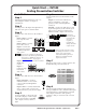
Quick Start — IN1508 Scaling Presentation Switcher Installation Step 6 Step 1 Connect audio devices to the switcher’s audio outputs. If desired, mount the switcher in a rack. See “Mounting the switcher” in chapter 2, “Installation”. Output A — Connect an audio device, such as an amplifier or powered speakers, to these left and right RCA connectors. Step 2 Step 3 Connect source video devices to the switcher’s inputs. Inputs 3 and 4 — Connect two S-video sources.
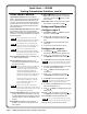
Quick Start — IN1508 Scaling Presentation Switcher, cont’d Front Panel Controls Input buttons and LEDs select and identify inputs. The green input LED indicates the input that is scaled and displayed in the main image window. If the Picture-in-picture (PIP) feature is turned on (the PIP On LED is lit), the red input LED indicates the input that is displayed in the PIP image window. Output Rate button and LEDs select and identify the switcher’s output rate.
Table of Contents Chapter 1 • Introduction ....................................................................................................... 1-1 About this Manual ............................................................................................................. 1-2 About the Switcher ............................................................................................................ 1-2 DVI video .......................................................................................
Table of Contents, cont’d Zoom selection .................................................................................................. 3-17 Pan selection ..................................................................................................... 3-17 Aspect ratio selection ........................................................................................ 3-17 Advanced screen ...............................................................................................
Chapter 4 • Serial Communications ............................................................................... 4-1 Host-to-Switcher Instructions ....................................................................................... 4-2 Switcher-Initiated Messages ......................................................................................... 4-2 Switcher Error Responses ...............................................................................................
Table of Contents, cont’d 68-791-01 Rev. G 03 08 All trademarks mentioned in this manual are the properties of their respective owners.
IN1508 Scaling Presentation Switcher 1 Chapter One Introduction About this Manual About the Switcher Features
Introduction, cont’d Introduction About this Manual This manual contains installation, configuration, and operating information for the Extron IN1508 Scaling Presentation Switcher (referred to in this manual as the “IN1508” or the “switcher”). • Chapter 1 identifies the switcher’s features. • Chapter 2 details how to install the switcher. • Chapter 3 describes how to operate the switcher from its front panel and use all of its features.
RS-232 Control UT TP OU A B L R L 6 T PU 4 IO D AU IN 5 8 R 7 3 2 1 UT TP L OU TED LIS 3 1T2 . U S I.T.
Introduction, cont’d Standard DVI cable DVI/DFP signals run at a very high frequency and are especially prone to bad video connections, too many adapters, or excessive cable length. To avoid the loss of an image or jitter, follow these guidelines: • Do not exceed 16.4 feet (5 meters) on the switcher’s input when using standard DVI cables. Extron’s IN9700 extension cable can be used to extend the length of the input cable. See “IN9700 cable”, below.
Audio outputs — The switcher provides an unbalanced line level signal that is identical to the input signal. This output can drive any line level compatible audio unit, or a local device such as powered speakers.
Introduction, cont’d Inverse 3:2 pulldown detection for NTSC video sources and 2:2 film detection for PAL video sources — This advanced film mode processing feature helps maximize image detail and sharpness for video sources that originated from film. When film is converted to NTSC video, the film frame rate has to be matched to the video frame rate in a process called 3:2 pulldown. Jaggies and other image artifacts can result if conventional deinterlacing techniques are used on film-source video.
Freeze mode — Provides a high quality still image for applications that require close examination of a specific video frame. Blank mode — Suppresses the output video image. Blank silences the R, G, and B video outputs but the switcher still outputs sync. This ensures that the output device does not lose sync lock. Blank mode operates for video and RGB signals that are processed by the scaling circuitry. On-screen displays are not blanked.
Introduction, cont’d 1-8 IN1508 Scaling Presentation Switcher • Introduction
IN1508 Scaling Presentation Switcher 2 Chapter Two Installation Mounting the Switcher Cabling and Rear Panel Views Remote Control Battery Installation Configuration
Installation, cont’d Installation Mounting the Switcher The IN1508 comes with rubber feet and a set of rack mounting brackets. Tabletop use Attach a self-adhesive rubber foot to each corner of the bottom of the switcher. Rack mounting UL requirements The following Underwriters Laboratories (UL) requirements pertain to the installation of the switcher into a rack (figure 2-1). 1.
Secure the switcher to the rack using the supplied machine screws. 3. Cabling and Rear Panel Views All connectors are on the rear panel (figure 2-2). 100-240V 50-60Hz I 1 VID 3 6 YC LISTED C VID OUTPUT 1 T 2 3 4 5 A 6 L L YC 7 U 50/60Hz OUTPUT AUDIO INPUT 1 RGB Y, B-Y, R-Y RGB P U S 1T23 I.T.E.
Installation, cont’d Audio connections 8 9 Input 1 through Input 5 connectors — Connect unbalanced stereo or mono audio sources (such as DVD players or VCRs) to these pairs (left and right) of RCA connectors for audio input. L R Input 6 through Input 8 connectors — Connect unbalanced stereo audio sources (such as computers) to these 3.5 mm mini stereo jacks for unbalanced audio input. Figure 2-3 shows how to wire the audio jack.
RS-232 connection 12 Remote port — Connect a host device, such as a computer or touch panel control, to the IN1508 switcher via this 9-pin D connector for serial RS-232 control (figure 2-5). 5 1 9 6 Female Pin 1 2 3 4 5 6 7 8 9 RS-232 — TX RX — Gnd — — — — Function Not used Transmit data Receive data Not used Signal ground Not used Not used Not used Not used Figure 2-5 — Remote port pin assignments See chapter 4, “Serial Communications”, for definitions of the SIS commands.
Installation, cont’d 2-6 IN1508 Scaling Presentation Switcher • Installation
IN1508 Scaling Presentation Switcher 3 Chapter Three Operation Front Panel Controls and Indicators Remote Control Buttons Operations Optimizing the Video Optimizing the Audio Troubleshooting
Operation, cont’d Operation Front Panel Controls and Indicators All of the switcher’s controls are on the front panel (figure 3-1). Many controls are duplicated on the IR remote control (figure 3-8 on page 3-7). Front panel LEDs provide graphic indication of some of the basic system functions. For more complex tasks, such as system configuration, the switcher has a menu system that is operated by using the front panel or IR remote control buttons.
Input controls 2 Input buttons — The Input 1 through Input 8 buttons (figure 3-3) select the associated video input to scale and output. The switch can be a cut or a fade, depending on the switch mode; see “Fade Switch selection box”, on page 3-24. Audio always follows (switches with) the front panel video selection.
Operation, cont’d Output Rate selection 3 Output Rate button — The Output Rate button (figure 3-4) cycles through the available output screen resolutions. Use this button to select the “sweet spot” resolution of the connected video display device. The switcher defaults to a refresh rate of 60 Hz with each resolution selection using the Output Rate button. Eight IN1508 output resolutions are not available from the front panel.
Picture-in-Picture controls 4 PIP buttons — PIP ON SWAP Figure 3-5 — Picture-in-Picture buttons On button — The PIP On button toggles the PIP function on and off. If you press and hold the PIP On button while you apply power to the switcher, the switcher toggles the output signal type between RGB and progressive component video. If an RGB signal type (RGBHV, RGBS, or RGsB) was selected the last time the switcher was powered, the signal type switches to component.
Operation, cont’d Picture Controls buttons PICTURE CONTROLS CONT/ COL/ SIZE BRT TNT CENTER Figure 3-6 — Picture Control buttons 5 Picture Controls buttons — The Picture Controls buttons provide a shortcut to select individual or groups of image adjustments that are adjusted using the , , , and buttons ( 7 ). These adjustments are also available via the menu system. Center control button — The Center button selects and deselects the display centering adjustment.
8 Enter button — The Enter button: • Activates a highlighted submenu or function in the IN1508 main menu system. • Exits a slider-type status indicator bar control. • Saves a changed value in a selection box control. See “Main menu system”, on page 3-16, and “Picture adjustments”, on page 3-25, for details.
Operation, cont’d A/V Mute — The A/V Mute button switches the output to a blank screen and silences the audio output. The blank screen and muted audio are deselected when a new input is selected. Freeze — The Freeze button toggles the freeze feature on and off. Freeze stops the image at the moment you activate the feature and outputs a still image. Freeze is deselected when a new input is selected. 12 Menu buttons — The Menu buttons function identically to the front panel Menu buttons.
Color/Tint control button — The Color/Tint button selects and deselects the display color and tint adjustment status indicator bars. The adjustment range for both color and tint is from 0 to 127. The Color/Tint control affects only certain interalaced component video, composite video, and S-video, as shown in the following table.
Operation, cont’d Input selection operation Each of the eight inputs is assigned to one of two groups (see figure 3-9 on the next page): • Low resolution — Inputs 1 through 4 (and input 5 if it is configured as interlaced component video; see “Input 5 selection”, on page 3-18) • High resolution — Inputs 6 through 8 (and input 5 if it configured as progressive component video/HDTV; see “Input 5 selection”, on page 3-18) Input selection acts differently, depending on whether PIP mode is on or off: • • PI
DVD DSS PC PC RGB 192 RGB 192 5:4 4:3 PC Graphics TV Uneven Frequency Response Rolloff 10 Rolloff 8 6 4 2 20 Input 1 Input 3 50 Input 6 100 10k 100k 1000 75k Frequency (Hz) Output Voltage Input 8 IN1508 INPUT IR 1 2 3 4 OUTPUT RATE 5 Low Resolution Input Group 6 PIP 8 7 ON VGA 1024x852 UXGA SVGA 1024x1024 720p XGA 1366x768 1080i SXGA 1365x1024 1080p High Resolution Input Group PICTURE CONTROLS CONT/ COL/ SIZE BRT TNT SWAP CENTER SCALING PRESENTATION SWITCHER
Operation, cont’d Menu system operation Figure 3-10 shows a flowchart of the submenus in the main menu system. Each submenu leads to a series of submenus or to “slider” type status indicator bar controls that accomplish individual tasks or groups of tasks. In figure 3-10, and all other flowcharts in this chapter, solid lines indicate screen changes initiated by the operator. Dashed lines indicate screen changes that are the result of a timeout function.
Menu button — Press the front panel or IR remote control Menu button to activate the menu system or to back up one level from the currently selected submenu or selection. (For example, pressing the Menu button in the Picture submenu turns off the Picture submenu selections and the switcher displays the main menu only.
Operation, cont’d Selection box control The selection boxes (figure 3-11) show a list of possible selections. When you first activate the selection box control, the selected option is marked with a . Use the front panel or IR remote control and buttons to move the to highlight other options. Highlighting a different option by moving the does not automatically select that option. You must push the front panel or IR remote control Enter button to change the selection.
Many status indicator bar controls can be activated in three ways (figure 3-12): • By navigating to the status indicator bar via the menu system • By pushing one of the front panel Picture Control buttons (such as Color/Tint) • By pushing one of the IR remote control picture control buttons (such as Color/Tint) Use the status indicator bars as follows: 1. If necessary, select the input that you want to adjust by pressing the appropriate input button. 2. For menu system operation: a.
Operation, cont’d Main menu system The main menu includes the following submenus: • Input submenu — Size, centering, and aspect ratio • Picture submenu — Image quality adjustments • Output submenu — Resolution, refresh rate, sync, and signal format • Audio submenu — Input audio volume and audio delay • Advanced submenu — Advanced options Input submenu Figure 3-13 is a flowchart that shows an overview of the Input submenu, its available selections, and their available settings.
Center selection The Center selection displays two status indicator bars that show, and allow you to adjust, the horizontal and vertical position of the main or picture-in-picture output on the monitor. If the PIP feature is turned off (the front panel PIP On LED is unlit), Center adjusts the position of the main window. If the picture-in-picture feature is turned on (the front panel PIP On LED is lit), Center adjusts the position of the PIP window.
Operation, cont’d Advanced screen The Input submenu’s Advanced settings are a comprehensive set of adjustments to optimize the switcher for non-standard video inputs. Most users do not encounter such signals. For those users who do, the switcher automatically adjusts these settings. The switcher’s automatic adjustments are adequate for most inputs. The Advanced screen provides a submenu of advanced selection options: active pixels, active lines, phase, horizontal and vertical start, and total pixels.
Brightness status indicator bar The Brightness status indicator bar shows, and allows you to adjust, the brightness setting for the selected input. Brightness adjusts the light intensity of the image on the screen. Use the front panel or IR remote control and buttons to adjust the brightness control through a range of 0 to 128. The default setting is 64. Contrast status indicator bar The Contrast status indicator bar shows, and allows you to adjust, the contrast setting for the selected input.
Operation, cont’d Output submenu Figure 3-15 is a flowchart that shows an overview of the Output submenu, its available selections, and their available settings. Use the front panel or IR remote control and buttons to highlight the desired selection and press the Enter button. Timeout No menu display Menu Menu INPUT Timeout Menu PICTURE Timeout Menu Menu OUTPUT Enter Resolution Enter Menu Timeout Press Enter to select a change.
Resolution selection box The front panel Output Rate button can also be used to select most resolutions, with the following exceptions: • 852 x 480 • 1440 x 900 • 1400 x 1050 • 1680 x 1050 The Resolution selection box identifies the currently selected output resolution and allows you to select a different output resolution. The table at right defines the combinations of resolutions and refresh rates that the switcher can output. The default resolution is XGA.
Operation, cont’d Signal Type selection box The Signal Type selection box identifies the currently selected output signal format (RGBHV, RGBS, RGsB, or progressive component video [Y, B-Y, R-Y]) and provides the ability to select a different type. To select a different sync type, use the front panel or IR remote control or button to highlight the desired sync type and press the enter button. The default setting is RGBHV.
Audio Delay selection box The Audio Delay selection box provides the ability to turn audio delay on and off. Audio delay compensates for the latency period that is inherent in deinterlacing NTSC, PAL, and SECAM video by delaying the audio output to match the video output. Use the front panel or IR remote control and buttons to select On or Off. The default is On.
Operation, cont’d Swap selection The Swap selection toggles the primary and secondary inputs between the main image and the PIP window. Select swap by highlighting the Swap selection and pressing the Enter or button. Repeatedly press the Enter or button to toggle between the main and PIP windows. Press the , , or button to deselect Swap, or allow the menu timeout (from the final button push) to clear the on-screen displays.
Performing a system reset from the front panel The front panel reset is identical to the Esc zXXX SIS command (see chapter 4, “Serial Communications”) and the system reset that is available through the reset system (see “Reset selection box” earlier in this chapter). But the front panel reset does not require a connected computer or a connected monitor to view the onscreen displays.
Operation, cont’d No menu display CENTER PIP ON Window Center H –OR– CENTER V Timeout CENTER PIP CENTER ON Image Center –OR– CENTER H Start 0 V Start +31 Timeout Press once Window Center H –OR– CENTER Press again V Timeout SIZE PIP ON PIP Size < 1/4 > –OR– SIZE Press to select a different PIP size.
No menu display ZOOM Zoom Timeout PAN H Pan V Timeout ASPECT RATIO Aspect Ratio 4:3 Press to change the aspect ratio. Timeout (0 to 63) SHARP Sharpness +32 Timeout (0 to 128) PHASE Phase +64 Timeout NOTE The The and and = IR remote control buttons toggle between the top and bottom selection where applicable. buttons move the slider on the selected status bar indicator.
Operation, cont’d Window Centering display — This display consists of two status indicator bars that show, and allow you to adjust, either the position (centering) of the main image or the position of the PIP window, depending on whether the PIP feature is off or on. PIP is off — Center adjusts the horizontal and vertical position of the main image on the monitor. The adjustment range depends on the input rate applied and the output resolution selected.
• Color/Tint: Color increases and decreases the color intensity of the picture. Tint is a relative measure of the amount of white in a given color and adjusts the picture’s color toward red or green. The color adjustment is also available by using the front panel or IR remote control to select Menu > Picture > Color in the main menu system (see “Color status indicator bar”, on page 3-19).
Operation, cont’d Front panel security lockout The front panel security lockout limits the operation of the IN1508 from the front panel. When the switcher’s front panel is locked out, all of the front panel image adjustment functions are disabled. You can still select inputs. To toggle executive mode on or off, simultaneously press and hold the Color/Tint and Center buttons (figure 3-21) for approximately 2 seconds. Release the buttons.
The ideal resolution must lie within the compatible range of the display. For example, some 27” to 36” presentation monitors are limited to input signals in the 30 kHz to 50 kHz range. Check the Direct View Display Cross Reference and the Projector Cross Reference on the Extron Web site (www.extron.com) for the most up-to-date compatible ranges of most displays.
Operation, cont’d Suggested sweet spot/ Suggested native resolution refresh rate Display type Comments CRT Displays 15" data monitor 800 x 600, 1024 x 768 72 Hz / 75 Hz 17" data monitor 1024 x 768 72 Hz / 75 Hz 1024 x 768, 1280 x 1024 72 Hz - 85 Hz 27"-42" presentation monitor 800 x 600, 1024 x 768 72 hz / 75 Hz Data projector or retro display with 7" CRTs 800 x 600, 1024 x 768 72 Hz - 85 Hz Data projector or retro displays with 9" CRTs 1024 x 768, 1280 x 1024 72 Hz - 85 Hz 19"-21" data
Input submenu’s Advanced selections Figure 3-22 shows the selections that are available from the Input > Advanced screen. The switcher automatically adjusts for different input and output modes. However, if the input signal has slightly different timing or is non-standard, some settings may need to be manually adjusted.
Operation, cont’d Vertical Start Total Lines Blanking Area Active Area Active Lines Horizontal Start Active Pixels Total Pixels Figure 3-23 — Advanced input settings • Total pixels (RGBHV/RGBS/RGsB and progressive/HDTV component only) — The total number of pixels per line, including the blanking on both sides of the input active area (active, horizontal sync width, back porch, and front porch).
Horizontal Start and Vertical Start status indicator bars The input start controls adjust where the electronic scaling process takes effect. The input start and active area should be manually adjusted, if necessary, to match the input video signal, framing the active area of the input signal. If the start is set incorrectly, the switcher may add blank borders on the leading edges (top or left side) or it may crop the active area on the trailing edges (bottom or right side).
Operation, cont’d Similarly, if the vertical start adjustment is set to less than the amount of actual blanking, the IN1508 starts scaling before the first line of the active image. This early scaling results in a blank border on the top and cropping on the bottom, and looks as if the image is shifted down. Adjust the H Start status indicator bar to shift the switcher’s starting point horizontally on the screen. Adjust the V Start status indicator bar to shift the starting period vertically on the screen.
default capture rate to the specified input frequency. It then maintains the aspect ratio based on the difference between the input active area and the output resolution (active area) by inserting blank borders around the images. If, however, you want to fill the entire monitor, you can adjust the input aspect ratio by slightly changing the number of active pixels and active lines to stretch the image. You may also need to adjust the number of total pixels.
Operation, cont’d Total Pixels status indicator bar There are several methods to determine the correct value to use in the total pixels variable. Usually, the best method is to use the input signal specifications. For some input sampling rates, the switcher’s setting can result in fine vertical lines (figure 3-26). Blanking Area Active Area Total Pixels Figure 3-26 — Incorrect total pixels variable These lines appear as fuzzy vertical bars when an alternating pixels pattern is applied.
Optimizing the Audio Each individual input audio level can be adjusted within a range of -53 dB to +9 dB, so there are no noticeable volume differences between sources and for the best headroom and signal-to-noise ratio. Adjust the audio gain and attenuation as follows: 1. Connect audio sources to all desired inputs and connect the audio output to an output device such as an audio player. See “Audio connections”, in chapter 2, “Installation”. 2.
Operation, cont’d Specific problems The table below shows some common operating problems and their solutions. Problem No image appears. Possible cause Power. No video input. No video output. The output signal is incompatible. The output format is incompatible for the display. The display may not accept the output sync format. Freeze mode was entered when the image was black. Video may be muted. No audio output. The image is scrambled.
Problem Possible cause Solution The image is stretched Total pixels may be set Select Picture>Advanced>Total horizontally. too high. Pixels and reduce the setting to match the input signal. Active pixels may be Select Picture>Advanced>Active set too low. Pixels and increase the setting to match the input signal. The image is Total pixels may be set Select Picture>Advanced>Total compressed too low. Pixels and increase the setting to horizontally. match the input signal.
Operation, cont’d Problem Possible cause The image is cropped Input vertical start on the bottom. may be set too low. Vertical position may be set too near to the bottom. Display may be set incorrectly. Frozen image. Output resolution cannot be increased. Select Picture>Advanced> V Start and increase the setting to match the input signal. Press the front panel Center button and shift the image up. Use the display’s position or size controls to fit the image on the display. Freeze is activated.
Problem Possible cause Total pixels setting cannot be increased. Active lines setting cannot be increased. Horizontal start setting cannot be increased. Vertical start. Solution Active pixels setting may be too low. Select Picture>Advanced>Active Pixels and increase the setting to match the input signal. Horizontal start Select Picture>Advanced>H may be too high. Start and reduce the setting to match the input signal. Output resolution may Press the front panel Output Rate be too low.
Operation, cont’d 3-44 IN1508 Scaling Presentation Switcher • Operation
IN1508 Video Scaler and Switcher 4 Chapter Four Serial Communications Host-to-Switcher Instructions Switcher-Initiated Messages Switcher Error Responses Using the Command/Response Table
Serial Communications The switcher’s rear panel Remote 9-pin D female connector (figure 4-1) can be connected to the RS-232 serial port output of a host device such as a computer running the HyperTerminal utility or a control system. This connection makes software control of the switcher possible.
Using the Command/Response Table The command/response table begins on the next page. Except for the gain and attenuation settings, upper or lower case letters are acceptable in the command field. Command and response examples are shown throughout the table. The table below shows the hexadecimal equivalent of each ASCII command. ASCII to HEX Conversion Table Space Symbol definitions Symbols ( Xn values), defined below, are used throughout the command/response table that begins on page 4-4.
Serial Communications, cont’d Command/response table for SIS commands Command ASCII Command Response (host to switcher) (switcher to host) Additional description Input selection and PIP swap Select video and audio input Example: View video and audio input Swap PIP and main windows X1 ! 2! ! % Chn X1 Chn02 Chn X1 Pch X1 Select video and audio input X1 . Select video and audio input 2. Input X1 is selected. X1 is the input in the PIP window.
Command/response table for SIS commands (cont’d) Command ASCII Command Response (host to switcher) (switcher to host) Additional description X5 ^ +^ –^ ^ Con X5 Con X5 Con X5 Con X5 Specify the contrast adjustment. Increase the contrast by one. Decrease the contrast by one. Show the contrast setting. +: –: : Hsz X25 Hsz X25 Hsz X25 Widen the picture. Make the picture narrower. Window width is X25 . +; –; : Vsz+ Vsz– Vsz X25 Make the picture taller. Make the picture shorter.
Serial Communications, cont’d Command/response table for SIS commands (cont’d) Command ASCII Command Response (host to switcher) (switcher to host) Additional description Pixel phase Set a pixel phase value Example: Increment pixel phase value Decrement pixel phase value View the pixel phase value X11 U Phs X11 6U +U –U U Phs6 Phs X11 Phs X11 Phs X11 Use a pixel phase setting of 6. Increase the pixel phase setting. Decrease the pixel phase setting. Pixel phase value is X11 .
Command/response table for SIS commands (cont’d) Command ASCII Command Response (host to switcher) (switcher to host) Additional description Set audio mute on 1Z Amt X4 Mute the audio output. Set audio mute off View audio mute status 0Z Z Amt X4 Amt X4 Unmute the audio output. Audio mute is X4 (on or off).
Serial Communications, cont’d Command/response table for special function SIS commands The syntax for setting a special function is Xn * X? # where Xn is the value or variable (such as X17 in the second example below), X? is the function number (such as “2” = “Set input 5 video format” in the second example below), and # is the execute command. To view a function’s setting, use X? #, where X? is the function number.
Command/response table for special function SIS commands (cont’d) Command ASCII Command Response (host to switcher) (switcher to host) 1*9# 0*9# 9# 9# Asp1 Asp0 Asp X21 Asp0 X22 *10# 3*10# Mnu X22 Mnu3 X23 *11# Tpx X23 Additional description Input aspect ratio Set the input aspect ratio to 16:9 Set the input aspect ratio to 4:3 View the selected aspect ratio Example: The aspect ratio is set to 4:3. Menu buttons Presses of the menu buttons Example: Emulate pushing a menu button.
Serial Communications, cont’d Command/response table for special function SIS commands (cont’d) Command ASCII Command Response (host to switcher) (switcher to host) Additional description EDID emulation (DVI input 8 only) Set EDID emulation Example: Read EDID emulation X2 * X3 *41# DDC X2 * X3 15*2*41# DDC15*2 41# DDC X2 * X3 Set the EDID to emulate a specific resolution (default: 1024 x 768 at 60 Hz). Set EDID emulation to 1080p at 60 Hz.
IN1508 Scaling Presentation Switcher A Appendix A Specifications and Part Numbers Specifications Part Numbers
Specifications and Part Numbers Specifications Video input Number/signal type ................... 2 composite video 2 S-video 1 component video (interlaced, progressive, or HDTV) 2 RGBHV, RGBS, RGsB 1 DVI-D digital video (single link) Connectors ................................... 2 female BNC (composite video) 2 female 4-pin mini DIN (S-video) 3 female BNC (component video) 2 female 15-pin HD (RGB) 1 DVI female (DVI-I) Nominal level ...............................
Max input voltage ........................ 5V p-p Polarity .......................................... Positive or negative (switch-selectable) Audio Gain ................................................ Frequency response .................... THD + Noise ................................. S/N ............................................... Crosstalk ....................................... Stereo channel separation .......... Unbalanced output: 0 dB; balanced output: +6 dB 20 Hz to 20 kHz, ±1.1 dB 0.
Specifications and Part Numbers, cont’d Shipping weight ........................... Vibration ....................................... Listings .......................................... Compliances ................................. MTBF ............................................. Warranty .......................................
High performance DVI cables Cable IN9700/6 DVI male to male 6' (1.8 meters) IN9700/25 DVI male to male 25' (7.6 meters) IN9700/35 DVI male to male 35' (10.6 meters) IN9700/50 DVI male to male 50' (15.2 meters) IN9700/75 DVI male to male 75' (22.
Specifications and Part Numbers, cont’d A-6 IN1508 Scaling Presentation Switcher • Specifications and Part Numbers
Extron’s Warranty Extron Electronics warrants this product against defects in materials and workmanship for a period of three years from the date of purchase.
www.extron.com Extron Electronics, USA 1230 South Lewis Street Anaheim, CA 92805 800.633.9876 714.491.1500 FAX 714.491.1517 Extron Electronics, Europe Beeldschermweg 6C 3821 AH Amersfoort, The Netherlands +800.3987.6673 +31.33.453.4040 FAX +31.33.453.4050 Extron Electronics, Asia 135 Joo Seng Rd. #04-01 PM Industrial Bldg., Singapore 368363 +800.7339.8766 +65.6383.4400 FAX +65.6383.4664 © 2008 Extron Electronics. All rights reserved.