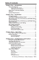
User’s Manual INTERCOM MIC ON INTERCOM MIC ON LEVEL HIGH MED LOW PUSH TO TALK PUSH TO TALK HELP DESK ROOM 101 1 2 LAB ADMIN OFFICE HELP DESK SECURITY LAB ADMIN OFFICE 3 4 1 2 3 4 IPI 104 IPI 204 LEVEL INTERCOM MIC ON INTERCOM MIC ON LEVEL HIGH MED LOW PUSH TO TALK LEVEL HELP DESK PUSH TO TALK IPI 201 HELP DESK IPI 101 IPI 100 Series IPI 200 Series MediaLink™ IP Intercom™ Interfaces 68-1170-01 Rev.
Precautions Safety Instructions • English This symbol is intended to alert the user of important operating and maintenance (servicing) instructions in the literature provided with the equipment. This symbol is intended to alert the user of the presence of uninsulated dangerous voltage within the product’s enclosure that may present a risk of electric shock. Caution Read Instructions • Read and understand all safety and operating instructions before using the equipment.
安全须知 • 中文 警告 这个符号提示用户该设备用户手册中 有重要的操作和维护说明。 电源 • 该 设 备 只 能 使 用 产 品 上 标 明 的 电 源 。 设 备 必须使用有地线的供电系统供电。 第三条线 (地线)是安全设施,不能不用或跳过。 这个符号警告用户该设备机壳内有暴 拔掉电源 • 为安全地从设备拔掉电源,请拔掉所有设备后 或桌面电源的电源线,或任何接到市电系统的电源线。 露的危险电压,有触电危险。 电源线保护 • 妥善布线, 避免被踩踏,或重物挤压。 注意 阅读说明书 • 用 户 使 用 该 设 备 前 必 须 阅 读 并 理 解所有安全和使用说明。 保存说明书 • 用户应保存安全说明书以备将来使 用。 遵守警告 • 用户应遵守产品和用户指南上的所有安 全和操作说明。 维护 • 所有维修必须由认证的维修人员进行。 设备内部 没有用户可以更换的零件。为避免出现触电危险不要自 己试图打开设备盖子维修该设备。 通风孔 • 有些设备机壳上有通风槽或孔,它们是用来防止 机内敏感元件过热。 不要用任何东西挡住通风孔。 锂电池 • 不正确的更换电池会有爆炸的危险。 必须使用 与厂家推荐的相同
This page has been intentionally left blank.
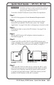
Quick Start Guide — IPI 101, IPI 104 W Installation and service must be performed by authorized personnel only. These products must be used with UL approved, grounded electrical boxes. To install an Extron IP Intercom® Sytem, follow the steps below: Step 1 Turn all of the equipment off and disconnect the power cords. Step 2 Select the installation location and install an electrical wall box for each IPI unit and MLC 226 IP in the system.
Quick Start Guide — IPI 101, IPI 104, cont’d Step 7 Install each MLC 226 IP and IPI into the wallboxes you installed in step 2 above. Step 8 Connect the console PC(s) to the network. Step 9 Connect the PC(s) and MLC(s) to power sources and turn on the PC(s). Step 10 Configure the MLC 226 IP. Refer to the MLC 226 IP User’s Manual and the Global Configurator help file for instructions. Step 11 Install the Extron IP Intercom HelpDesk™ software on a PC.
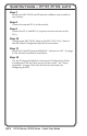
Quick Start Guide — IPI 201, IPI 204 W Installation and service must be performed by authorized personnel only. These products must be used with UL approved, grounded electrical boxes. To install an Extron IP Intercom® System, follow the steps below: Step 1 Turn all of the equipment off and disconnect the power cords. Step 2 Select the installation location and install an electrical wall box for each IPI 201 or IPI 204 unit in the system.
This page has been intentionally left blank.
Table of Contents Chapter One • Introduction ................................................... 1-1 About this Manual ..................................................................... 1-2 Terms used in this manual ..................................................... 1-2 Additional reference material . .............................................. 1-2 About the IP Intercom Modules ............................................ 1-2 Features ...............................................................
Table of Contents, cont’d Configuring the IPI Intercom System ................................. 4-16 Parts of the Configuration Utility screen ............................ 4-17 Configuration Utility menus . ...............................................4-18 Tools menu .........................................................................4-18 Help menu ..........................................................................4-19 Setup procedure ..........................................................
IPI 100 Series, IPI 200 Series 1 Chapter One Introduction About this Manual About the MediaLink™ IP Intercom® Modules Features System Requirements
Introduction About this Manual This manual describes how to configure and operate the following Extron MediaLink™ IP Intercom® Modules: • IPI 101 AAP • IPI 104 AAP • IPI 201 Series • IPI 204 Series N The IPI 201 and IPI 204 series include AAP and 2-gang version intercoms. Terms used in this manual • The terms “IPI” and “intercom” are used interchangeably in this manual to refer to all models.
N The IPI 201 and IPI 204 are stand-alone units that do not require a connection to a MediaLink controller. MediaLink IP Intercom HelpDesk software is installed on a central office or help desk PC to configure and manage IP Intercom System operations. Connections between the IPI 101 AAP and IPI 104 AAP intercoms with MLC 226 IP and the network are via existing network drops using standard CAT 5, CAT 5e, or CAT 6 cables.
Introduction, cont’d Features • Two-way, half-duplex voice communications over an IP network • Compatibility with IP Intercom-enabled MLC 226 IP MediaLink Controllers (IPI 101 AAP and IPI 104 AAP) • Backlit, configurable Push To Talk buttons • Integrated speaker and microphone • Three-position switch to adjust speaker volume levels (IPI 101 AAP and IPI 104 AAP only) • LED indicator to show when the room is being monitored • Four space and 2-gang Architectural Adapter Plate (AAP) opening mounting • Connectio
IPI 100 Series, IPI 200 Series 2 Chapter Two Installation UL Requirements Installing or Replacing Button Labels Mounting the IPI 101 or IPI 104 into an AAP Wall Plate or Device Faceplate Mounting the IPI 201 or IPI 204 into an AAP Wall Plate or Device Faceplate IPI Rear Panel Features and Cabling MLC Audio Connection Sample Applications
Installation W Installation and service must be performed by authorized personnel only. This product should be used with a UL approved electrical box. See “UL Requirements”, below. N The MLC 226 IP to which the IPI intercom is connected must have been shipped after November 16, 2005 and also have firmware version 1.05 or later to support the IPI. To set up the IPI you must use the IPI Intercom HelpDesk. software. UL Requirements 1.
2. Locate the small corner notch on the lens cap and slide the screwdriver between the lens cap and the diffuser, as shown in Ç. Using a rotating motion of the screwdriver (see É), carefully pry the two pieces apart. 3. Replace the label with the new button label. 4. Press the lens cap and diffuser together and reinstall the button assembly into its plunger/base. 5. Repeat steps 1 through 4 for each button you plan to relabel.
Installation, cont’d Mounting the IPI 101 or IPI 104 into an AAP Wall Plate or Device Faceplate The IPI intercom and any other adapter plates must be attached to a device faceplate or AAP wall plate and cabled before the device or wall plate is installed in a wall or furniture. The screws needed for installing the IPI are built into its front panel. 1. Before cables are attached, insert the IPI’s screws through the holes in the device’s faceplate or AAP mounting frame.
Mounting the IPI 201 or IPI 204 into an AAP Wall Plate or Device Faceplate The IPI 201 and IPI 204 intercoms must be attached to a device faceplate or AAP wall plate and cabled before the device or wall plate is installed in a wall or furniture. Unlike the IPI 100 Series intercoms, the IPI 200 AAP Series intercoms are secured by attaching a clamp bracket to the back of the intercom after it has been inserted through the front of the AAP plate. 1.
Installation, cont’d IPI Rear Panel Features and Cabling 1a Intercom Port 2 AAP Mounting Screws (4) IPI 104 AAP, IPI 101 AAP Rear Panel POWER Power 3 Contact Relay 4 Audio Out 5 C NO RELAY 1b LAN Port AUDIO OUT LAN 2 AAP Mounting Screws (4) IPI 204 AAP, IPI 201 AAP Rear Panel Ä Intercom port (IPI 101 AAP and IPI 104 AAP only) — This port is used for power, control, and voice data communication with the MLC.
<100’ (30.4 m) INTERCOM R HOST CONTROL AUDIO OUT LAN 1=DIGITAL I/O 2=Tx 3=Rx 5=GND 38400, N, 8, 1 IPI 101 AAP or IPI 104 AAP Rear Panel Å MLC 226 IP Rear Panel LAN port (IPI 201 AAP and 204 AAP only) — Plug an RJ-45 jack into the LAN connector to connect to a network. The blinking yellow LED indicates LAN activity. The green LED lights to indicate a good LAN connection.
Installation, cont’d e Audio Out — A 3-pole, 3.5 mm captive screw connector is used for audio output connection. It provides a -10 dBV unbalanced signal that can be connected to local, powered speakers or to any audio or paging system. MLC Audio Connection The MLC 226 IP Series controllers that support IPI intercom panels also have a rear panel, line level audio output port that can be connected to local, powered speakers or to any audio or paging system. See the wiring guide in the illustration below.
3. The intercom user presses and holds the button assigned to the PC to initiate talk mode. The button glows bright amber, and the Mic On LED lights. 4. The user speaks into the intercom. Audio is output through the PC speakers at the help desk console. 5. The intercom user releases the button when done speaking. 6. The console operator clicks the Talk button (in the software) or presses the PC’s space bar to respond. Help Desk Console IP 10.XX.XX.01 Audio Card Office IP 10.XX.XX.
2-10 IPI 100 Series, IPI 200 Series • Installation OFF MUTE AUTO IMAGE IR CONFIG PC 3 6 2 5 1 4 LAPTOP AUX VIDEO DVD VCR MLC 226 IP AAP VOLUME ON PROJECTOR Classroom IP 10.XX.XX.04 INTERCOM PUSH TO TALK MONITOR IPI 101 MLC 226 IP IPI 101 AAP HELP DESK LOW MED HIGH LEVEL OFF MUTE AUTO IMAGE IR LAPTOP 1 4 VCR CONFIG 2 5 DVD MLC 226 IP AAP VOLUME ON PROJECTOR Classroom IP 10.XX.XX.
3. Configure the intercoms and set up the intercom list for each console PC. Each console could be set up to monitor a different group of intercoms, but most likely the lists will overlap. In this example, an installation in one building of a college campus, each room (classroom, lab, or office) contains an intercom. Configure one button on each intercom to contact the computer help desk, and another button on each intercom to contact the campus security department.
Installation, cont’d Configuration Console PC IP 10.XX.XX.01 Connect for configuration. This connection is not needed for later operation. TCP/IP Network Straight-through Network Cable Classroom IP 10.XX.XX.02 PROJECTOR ON OFF INTERCOM AUTO IMAGE VCR DVD AUX VIDEO 1 4 2 5 3 6 MIC ON Lab IP 10.XX.XX.
SPW 82 SPW 82 TWO WAY IN-WALL LOUDSPEAKER 1" TITANIUM SWIVEL TWEETER 8" WOOFER TWO WAY IN-WALL LOUDSPEAKER 1" TITANIUM SWIVEL TWEETER 8" WOOFER SI 26W ON LEVEL STEREO BASS TREBLE LIMITER OFF MPA 122 DUAL MONO MINI POWER AMPLIFIER MPA 122 OUTPUTS 4/8 Ohms INPUTS C POWER 12V 3A MAX US L REMOTE R L R 10V VOL/MUTE L R MPA 122 IPI 104 AAP, IPI 101 AAP Rear Panel INTERCOM R HOST CONTROL LAN AUDIO OUT 1=DITIGAL I/O 2=Tx 3=Rx 5=GND 38400, N, 8, 1 PRESS TAB WITH TWEEKER TO REMOVE MLC
Installation, cont’d 2-14 IPI 100 AAP, IPI 200 AAP Series • Installation
IPI 100 Series, IPI 200 Series 3 Chapter Three Operation Front Panel Features and Operation Button Operation
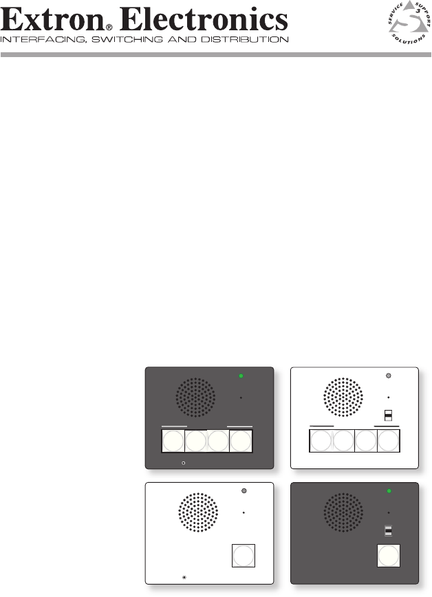
Operation Front Panel Features and Operation a b c d 3-2 Speaker — This integrated speaker provides mono output at the IPI panel. Mic On LED — This LED lights under two circumstances: • When a configured Push to Talk button is pressed. • To indicate that someone at the help desk console is listening and that the intercom is in monitoring mode. Monitoring mode permits hands-free operation: the user does not have to press the Push to Talk button to speak into the intercom.
e Push to Talk button(s) — The IPI 101 AAP and IPI 201 units include one of these buttons, and the IPI 104 AAP and IPI 204 units have four. N The MLC and IPI intercoms must be configured (via software) to associate each button with the IP address of a specific console PC or intercoms. Once configured, the IPI 101 AAP and IPI 201 can communicate to one location (one IP address). The IPI 104 AAP and IPI 204 can communicate with up to four different locations. f Config Port (IPI 200 Series only) — This 2.
Operation, cont’d Indication (lighting) 3-4 Button Color Indication Amber (dim) • The button is in standby. • The device at the IP address associated with that button is turned on and is connected to the network. If that device gets disconnected or if the help desk software is not running on that PC, the button lights red. Once it is reconnected, the button returns to dim amber lighting. Amber (bright) • The IPI is communicating with the location the button is configured to call.
IPI 100 Series, IPI 200 Series 4 Chapter Four Configuration and Control Software System Requirements Installing the Software Using the Software: an Overview Parts of the Main Screen Main Screen Menus Configuring the IPI Intercom System
Configuration and Control The IP Intercom® System can be set up remotely and controlled using the IP Intercom HelpDeskTM software and a host computer (console PC). To function together, the PC must be network-capable with the proper protocols, and, when using IPI 100 AAP series intercoms, the MLC 226 IP must be connected to a LAN (local area network). See “Software-and Web Page-based Setup and Control“ in the MLC 226 Series User’s Manual for IP setup instructions.
Using the Software: an Overview The software allows configuration access only to administrators to prevent other users from making changes to • HelpDesk preferences • the system configuration including the set of intercoms with which a given help desk console can communicate • how the buttons on those intercoms are configured • advanced audio settings for each intercom • the Listen controls If the help desk operator does not log on as an administrator or user, help desk operators can still use the main scre
Configuration and Control, cont’d IP Intercom HelpDesk screen before configuration After configuration, the software screen lists the devices to be managed by the console, indicates their status (connected, disconnected, communicating), and provides several tools. Once units are configured, you can perform the following tasks: • Initiate calls from any intercom to the console (the PC running the software) or from the console to any intercom or group of intercoms.
IP Intercom HelpDesk screen after configuration Parts of the Main Screen Each area of the IP Intercom HelpDesk software’s main screen provides a different set of functions and/or information. Refer to the picture below as a guide to this screen.
Configuration and Control, cont’d a b Menu bar — See “Main Screen Menus” on page 4-12 for details on the drop-down menus available here. Talk Mode area — The Talk Mode section of the IP Intercom HelpDesk is used to speak or play announcements to other intercoms or help desks. Speaking to an intercom 1. Select an intercom from the Active Intercom List. 2. Click the Talk button. 3. Speak into the headset.
1. In the Active Intercom List, select an intercom and assign it to a group using the Group drop-down menu in the Group column. After an intercom has been assigned to a group the group number shows in the Group selection area. 2. Select one or more group number buttons on the left of the Group Selection area. N Only groups containing intercoms are available, the rest are inactive (grayed-out). 3. Click the Play Sound Bite button. 4. Select an announcement from the Sound Bite Selection window. 5.
Configuration and Control, cont’d c 3. Select an announcement from the Sound Bite Selection window. 4. Click the Play to Intercom(s) button. 5. After the announcement is played, repeat the process to send a different message or click the Exit button to close the Group Selection window. Listen Mode area — These controls determine the help desk console’s listening modes and options. The console can listen to only one intercom at a time. Listening to an intercom To listen to an intercom: 1.
2. Select Reject Calls or Forward Calls. If the Reject Calls option is set, no calls are accepted. The Forward Calls option sends the call to another help desk. 3. Click Accept Calls to return to the Listening mode. Hands-free operation For hands-free operation for both the help desk and the intercom user, select Automatic. The intercom user presses the intercom’s button once to activate the microphone and put the console into Listen mode.
Configuration and Control, cont’d NO INCOMING CALLS is displayed when no calls are coming into the help desk. INCOMING CALL along with the name and IP address of the calling intercom is displayed when a call is received. LAST INCOMING CALL displays after a call is answered or forwarded. g Active Intercom list — This area shows the list of intercoms being managed by the console.
Advanced Settings — available in the active intercom list area and from the Intercom menu. 1. Right-click on the intercom’s row and select Advanced Settings. or Select Advanced Settings... from the Intercom menu. If prompted to do so, type in an administrator password and click OK. The Advanced Settings dialog box opens: h 2. In the Advanced Settings dialog box, move the Remote Speaker and Remote Line controls to the right to increase their output levels. These adjustments take effect immediately. 3.
Configuration and Control, cont’d To save or clear the activity log, select Activity Log from the Tools menu. Activity logs are saved as text (*.txt) files. i Status bar — The status bar displays general information including the console PC’s IP address, the number of active intercoms managed by that console, the number of calls waiting, and the time of day.
you can set up or modify an intercom system. • Log off, Log on...— from help desk administrator or user status. Preferences are discussed in “Setting preferences” on page 4-13.” See Configuring the IPI Intercom System“ on page 4-16 for instructions on how to configure the system after you select Configuration Utility from the Tools drop-down menu. Intercom menu The Intercom drop-down menu contains the following functions: • Advanced Audio Settings — Use this to make adjustments to individual intercoms.
Configuration and Control, cont’d Setting preferences 1. From the main help desk screen, click on the Tools menu and select Preferences. A HelpDesk Preferences dialog box (shown on the next page) appears. 2. Select the desired settings for the system’s console (PC)intercom operations. 3. Click OK to accept the settings and return to the main screen. The HelpDesk Preferences features are as follows: a General Options Play recurring alert tone...
the HelpDesk’s Listen button is first activated or when the intercom user presses a Push to Talk button and connects with a help desk. The intercom plays a 2-tone beep when the Listen button is deactivated or the Push to Talk button is pressed and released to end a call. If this check box is cleared, the intercom does not sound to indicate an incoming call.
Configuration and Control, cont’d If you click BUSY Answer Later, the intercom plays a message indicating that the support staff is busy. Audio Notification — If you select Audio Notification, when an intercom user presses a button, the help desk operator hears an alert tone. Flash Screen for: — Use this option to set the duration of the display of the Incoming Call Alerts window between 0 and 300 seconds.
3. Add intercoms to the intercom list and click Update Intercom List. 4. Configure each intercom and click Apply. See the “Configuration” section in this chapter for details. 5. Exit the configuration utility. The main screen is now accessible. 6. Click on the Tools drop-down menu and select Preferences. 7. Select the desired settings for the system, then click OK to accept the settings and return to the main screen. See “Setting preferences” on page 4-13. 8.
Configuration and Control, cont’d b c Add Intercom area — This area lets you select from three ways to add intercoms to the list of intercoms the help desk console will monitor. See “Setup procedure” in this chapter for details. The button on the right side of this area changes from Import to Add or Scan depending on the method you select for adding intercoms. Intercom List area — The intercoms listed in this area will be served by the help desk console once you click the Update Intercom List button.
• Upload the “Station Not Present” Wave File to Intercom — Load the default file named nortxeStationNotPresent.wav to the selected MLC’s or IPI 201/204 series intercoms’ memory. If the intercom user calls the help desk while the intercom button lights red (the operator is unavailable or the help desk software is closed), this message is played at the intercom. You can replace the factory default recording with one of your choice, but the file you use must be named nortxeStationNotPresent.
Configuration and Control, cont’d • About — Select to see information about the IP Intercom HelpDesk software. Setup procedure Follow the steps below to set up the system. 1. Double-click on the IPI icon under the Extron group or folder. 2. Click on the Tools drop-down menu and select Configuration Utility. You may be prompted to enter an administrator password. The Configuration Utility opens in a separate window. 3. Create a list of intercom-enabled MLC 226 IPs and IPI 201/204 series intercoms.
Manually by IP Address — To use this option, type the IP address of an intercom-equipped MLC 226 IP and IPI 201/204 series intercoms into the blank area to the right of this selection, then click the Add button. Repeat that process for each intercom system to add to the Intercom List. Automatic — To add intercom-enabled MLCs and IPI 201/204 series intercoms to the list automatically, select the automatic option and click the Scan button.
Configuration and Control, cont’d To change the MLC/ intercom’s name as it appears in the IP Intercom Management software, right-click on that MLC/intercom’s name, select Rename, then type in the new name. You must click the Update Intercom List button for this change to take effect in the software. This action does not affect the name stored in the MLC/intercom’s flash memory. 4.
the Microsoft Windows operating system) to make your own WAV files. You need a Windows-based PC with a compatible microphone or other audio input device installed. Follow the procedure below. Recording an original message 1. Click the Start button. 2. In the Start menu, select All Programs > Accessories > Entertainment > Sound Recorder. 3. From the Sound Recorder’s File menu, select New. 4. To begin recording, click the Record button and speak into the microphone . 5.
Configuration and Control, cont’d 8. Type in a name for the new file in the file name area, and select the WAV file type. 9. Click the Change button. The Sound Selection window appears. Recorded sounds are saved as waveform (.wav) files. The Windows Sound Recorder default format is PCM 22.050 kHz, 16-bit, stereo. The IPI Intercom System requires different settings. 10. In the Sound Selection dialog box, click on Attributes and select the audio format of PCM, 8.0 kHz, 16 bit, mono, as shown below. 11.
3. From the Sound Recorder’s File menu, select Properties. The Properties dialog box appears (as shown above), displaying the duration, file size, and audio format of the selected file. 4. Click the Convert Now button. The Sound Selection window appears. 5. In the Sound Selection dialog box, click on Attributes and select the audio format of 8.0 kHz, 16 bit, mono, as shown in step 10 on the previous page. 6. Click the OK button to approve that audio format. The Save As window reappears. 7.
Configuration and Control, cont’d 4-26 IPI 100 Series, IPI 200 Series • Configuration and Control
IPI 100 Series, IPI 200 Series 5 Chapter Five IPI 201 and IPI 204 Series SIS™ Programming and Control Host-to-IPI Communication IPI-initiated Messages Commands and Responses
IPI 201/204 SIS™ Programming and Control The Extron MediaLink IP Intercom modules can be remotely set up and controlled via a host computer or other device (such as a control system) attached to the LAN port, or the front panel Config port. N Refer to the MLC 226 IP Series User’s Manual for IPI 101/104 series SIS command and control information. The IPI can be set up and controlled by using Extron’s Simple Instruction Set (SIS) commands, accessed via RS-232 or Ethernet LAN connection.
(c)Copyright 2007, Extron Electronics, IPI 201 V1.00, 60-809-00 ] Mon Day, DD Mon YYYY HH:MM:SS (c)Copyright 2007, Extron Electronics, IPI 204, V1.00, 60-810-00 ] Mon Day, DD Mon YYYY HH:MM:SS Vx.xx is the firmware version number.
IPI 201/204 SIS™ Programming, cont’d E17 – System timed out E22 – Busy E24 – Privilege violation E26 – Maximum number of connections has been exceeded E27 – Invalid event number E28 – Bad filename or file not found E30 – Hardware failure (followed by colon and descriptor number) (This is an unsolicited response.
using URL-encoded commands. The ASCII and URL commands listed in the tables starting on page 5‑8 perform the same functions, but they are encoded differently to accommodate the requirements of each port (Telnet or browser). The ASCII to hexadecimal (HEX) conversion table shown above is for use with the command/response tables.
IPI 201/204 SIS™ Programming, cont’d the pipe character. With the Web browser, you are required to use a “W” command and the pipe character. In either method, {Data} = data that will be directed to a specified port and must be hex encoded if non-alphanumeric. N If you make adjustments (changes to volume, etc.), whether via the front panel or via RS-232 or IP communication, it will take 1 minute 40 seconds (100 seconds) for the data in the IPI 200 series’ RAM to be saved to flash memory.
X1$ = IP address (xxx.xxx.xxx.xxx). Leading zeros in each of four fields are optional in setting values, and they are suppressed in returned values. IPI’s default address: 192.168.254.254 Default broadcast address: 255.255.255.255. X1% = X1* = X1( = E-mail domain name; for example, extron.
IPI 201/204 SIS™ Programming, cont’d X4^ = E-mail recipient’s address (e.g., JDoe@extron.com) for the person to whom messages will be sent. The e-mail address has a 31-character maximum. X4& = X4( = Name (numeral) of e-mail file to be sent X5@ = Connection’s security level 11 = user 12 = administrator X6# = Pulse time in 20 ms per count. If this parameter is missing or = 0, then pulse length = default = 25 = 500 ms. 1 = 20 ms (minimum pulse time) to 65535 = 1310700 ms (maximum pulse time).
IPI 100 Series, IPI 200 Series • Programming and Control 5-9 1%2A3%2AX6# O 1*3*X6# O 1O Pulse relay View the relay state 1X X X 1X X X Disable lockout mode24 View the lockout mode status Example: 0X 0X Off24 Front panel security lockout modes (executive modes) 1O 0] X20(] Exe 1] Exe 0] Rly 1 * X%] Rly 1 * X%] Rly 1* X%] Rly 1 *0] Rly 1 *1 (intercom to host) Response Toggle relay on/off. = 1 (on) or 0 (off). X% Turn relay on. Turn relay off.
Status commands 5-10 IPI 100 Series, IPI 200 Series • Programming and Control 11S 12S 13S 14S 15S 20S 12S 13S 14S 15S 20S (host to intercom) URL Encoded (Web) 11S (host to intercom) ASCII (Telnet) Additional description X20&] +X20^] +X20^] +X20^] +X20^] responses from commands 12S•13S•14S•15S•16S•20S ] (intercom to host) Response N In a query response, an asterisk (*) after the version number indicates the version that is currently used. A question mark (? or ?.
IPI 100 Series, IPI 200 Series • Programming and Control 5-11 1Q Q or 1Q (host to intercom) ASCII (Telnet) Example: Query bootstrap firmware version Example: 2Q 2Q 0Q Query verbose firmware version information 0Q Example: Query firmware version number Command 2Q 2Q 0Q 0Q 1Q Q or 1Q (host to intercom) URL Encoded (Web) Show the IPI’s firmware version (X1!) to two decimal places.
5-12 Example: Query factory firmware version Command 3Q 3Q (host to intercom) ASCII (Telnet) 3Q 3Q (host to intercom) URL Encoded (Web) Additional description Factory-installed firmware is different from the bootstrap firmware, but it is also not user-replaceable. This firmware was installed at the factory; it is the version the controller reverts to after a mode 1 reset (see chpt. 2). 1.00(1.
IPI 100 Series, IPI 200 Series • Programming and Control 5-13 4Q 32Q N Query FPGA version Request the IPI’s part number 4Q (host to intercom) ASCII (Telnet) Example: Query updated firmware version Command N 32Q 4Q 4Q (host to intercom) URL Encoded (Web) Additional description X1! (kernel version–model description–date time of upload)] or Ver04*X1! (kernel version–model description–date time of upload)] Use this command to find out which version of the firmware, if any, was uploaded into
5-14 1I 2I 3I 4I 32I Request the model description Request system memory usage Request user memory usage Query IPI module (host to intercom) ASCII (Telnet) Request the model name Command 32I 4I 3I 2I 1I (host to intercom) URL Encoded (Web) Stand-alone IPI Intercoms Additional description # bytes used out of # of kbytes] or Inf04*# bytes used out of # of kbytes] Show amount of user memory used and total available user memory.
IPI 100 Series, IPI 200 Series • Programming and Control 5-15 (host to intercom) ASCII (Telnet) W%20CN| WCN| E X1@ CN} E •CN} E CN} Set unit name to factory default24 Read the unit name W X1@ CN| (host to intercom) URL Encoded (Web) Set the unit name24 IP setup commands Command X1@ ] or Ipn•X4( ] Ipn• X1@ ] X4( ] (intercom to host) Response default name. X4( is the IPI’s factory defined unit name.
W X1# CT| W CT| W X# CZ| WCZ| E X1# CT} E CT} E X# CZ} E CZ} Set date/time24 Read date/time Set GMT offset24 Read GMT offset URL Encoded (Web) (host to intercom) ASCII (Telnet) (host to intercom) Command 5-16 X# ] Ipz X# ] X1# ] Ipt• X1# ] (intercom to host) Response format. The Read format is day of week, DD month year HH:MM:SS. Example: Fri, 08 Sept 2006 18:19:33. Set the Greenwich Mean Time (GMT) offset value (X#) for the IPI’s location. GMT offset (‑12.00 to +14.
IPI 100 Series, IPI 200 Series • Programming and Control 5-17 WX3$ CX| E X3$ CX} Ipx X3$ ] (intercom to host) Response View DHCP mode Set IP address24 Set DHCP off24 Additional description W CX| W1DH| E CX} E 1 DH} E 0 DH} Idh 1 ] X3$ ] WDH| W X1$ CI| E DH} E X1$ CI} Ipi• X1$ ] X% ] xxx.xxx). Leading zeros in each of the four fields are optional in setting values. X1$ = IP address (xxx.xxx. X% = 0 (off) or 1 (on).
W CI| WCH| W X1( CS| WCS| W X1$ CG| WCG| E CI} E CH} E X1( CS} E CS} E X1$ CG} E CG} Read IP address Read hardware address (MAC) Set subnet mask24 Read subnet mask Set gateway IP address24 Read gateway IP address URL Encoded (Web) (host to intercom) ASCII (Telnet) (host to intercom) Command 5-18 X1$ ] Ipg• X1$ ] X1(] X1* ] or Iph•X1* ] Ips• X1( ] X1$ ] (intercom to host) Response X1$ = IP address (xxx.xxx. xxx.xxx). Leading zeros are optional. xxx.xxx).
IPI 100 Series, IPI 200 Series • Programming and Control 5-19 (host to intercom) W X2@ CV| E X2@ CV} URL Encoded (Web) (host to intercom) ASCII (Telnet) Vrb X2@ ] (intercom to host) Response Enable or disable the verbose mode via this command.
5-20 View the broadcast mode Set the broadcast mode to the default address24 Clear the broadcast mode24 Read verbose mode status Set the broadcast mode24 Command (host to intercom) WCV| W X6$%2C X1$ EB| W X6$ EB| W 0 EB| W EB| E CV } E X6$,X1$ EB } E X6$ EB } E 0 EB } E EB } URL Encoded (Web) (host to intercom) ASCII (Telnet) X6$,X1$ ] Bmd 000,255.255.255.255] Bmd X6$,255.255.255.
IPI 100 Series, IPI 200 Series • Programming and Control 5-21 Bpt {port#}*X1* ] {port#}*X1* ] W{port#}*X7! , X7@ PB| WPB| E {port#}*X7! , X7@ PB} E PB} (intercom to host) Response (host to intercom) URL Encoded (Web) (host to intercom) ASCII (Telnet) N Changes to the PB command become effective in kernel versions 1.53 or higher.
IPI 100 Series, IPI 200 Series • Programming and Control E X3# CA } 5-22 Set administrator password24 Password and security settings (host to intercom) ASCII (Telnet) Command W X3# CA | (host to intercom) URL Encoded (Web) Ipa• X4! ] (intercom to host) Response Set the administrator access password (X3#, 4 to 12 alphanumeric characters). The password is case sensitive. Special characters (spaces, symbols) are not allowed. X4! = Password to display on screen (response to password query).
IPI 100 Series, IPI 200 Series • Programming and Control 5-23 (host to intercom) ASCII (Telnet) (host to intercom) URL Encoded (Web) (intercom to host) Response Additional description Clear Clear/remove all passwords E • CA } W%20 CA ] Ipa• ] administrator (administrator and user). password24 N A user password cannot be assigned if an administrator password does not exist. Also, if the administrator password is cleared, the user password is also cleared.
5-24 IPI 100 Series, IPI 200 Series • Programming and Control (host to intercom) URL Encoded (Web) (intercom to host) Response Additional description N If you remap a port, you must set the port number to 1024 or higher, unless you reset the port to the default number or disable the port by setting it to 0. Set the Telnet port E {port#}MT } Select a number for the port W{port#}MT| Pmt {port#} ] map24 that will not conflict with any other ports.
IPI 100 Series, IPI 200 Series • Programming and Control 5-25 (host to intercom) W{port#}MD| W2001MD| W0MD| WMD| E {port#}MD } E 2001MD } E 0MD } E MD } E path/directory/ CJ } {port#} ] Pmd 00000 ] Pmd 02001 ] Pmd {port#} ] (intercom to host) Response This resets the direct access port to port 2001.
5-26 Change back to the root directory Go up one directory level View the current directory Example: Example: Example: Command (host to intercom) URL Encoded (Web) (intercom to host) Response Dir•/] W %2F CJ| W %2E %2E CJ| W CJ| E..
IPI 100 Series, IPI 200 Series • Programming and Control 5-27 (host to intercom) ASCII (Telnet) (host to intercom) URL Encoded (Web) (intercom to host) Response Additional description {responds with 4‑bytes of file-size + raw undprocessed data in file}} E Retrieve file from user flash memory N Updating firmware can be done by loading an .S19 file with this command. If the box determines that the .
5-28 (host to intercom) ASCII (Telnet) Erase the usersupplied Web page and files24,28 Erase the current directory and its files24,28 Erase the current directory and its subdirectories24,28 W filename EF| W %2F EF| W %2F %2F EF| E/EF} E//EF} Use a POST on port 80 followed by the delimited data to be written to the flash file memory. Send a page GET on port 80 followed by: WSF| (e.g. http://192.168.254.254/ mypage.
IPI 100 Series, IPI 200 Series • Programming and Control 5-29 (host to intercom) WDS| W DF| DF} E E DF} URL Encoded (Web) (host to intercom) ASCII (Telnet) Additional description Retrieve a list of files stored in the controller. Each line of the response lists a different filename and its corresponding file size. The last line of the response indicates how much available file space there is.
5-30 Example (via Telnet or HyperTerminal): Command E DF} (host to intercom) ASCII (Telnet) W DF| (host to intercom) URL Encoded (Web) Additional description 4.evt Tue, 01 Mar 2005 02:03:07 GMT 42233] 1.eml Tue, 01 Mar 2005 02:03:34 GMT 200] 2.eml Tue, 01 Mar 2005 02:03:34 GMT 300] 2.eir Tue, 01 Mar 2005 02:03:34 GMT 1683] 6.evt Tue, 01 Mar 2005 02:03:36 GMT 17956] 4.eir Tue, 01 Mar 2005 02:03:47 GMT 6849] IPImain.sc Tue, 01 Mar 2005 02:03:52 GMT 8515] 0.
IPI 100 Series, IPI 200 Series • Programming and Control 5-31 #####] or Enm #####] WAE| The response is the quantity of currently running events, and it includes leading zeros. For example, if two events are running, the response is 00002]. The response is the same except that the path/directory prece filenames for files within the subdirectories.
5-32 (host to intercom) ASCII (Telnet) (host to intercom) URL Encoded (Web) (intercom to host) Response Additional description N The ZY command appears n kernel versions 1.45 or higher. Absolute system E ZQQQ} WZQQQ| Zpq] reset N (Mode 5 reset) Resets alls device settings, including IP settings, to factory default. Also rerases flash memory. Firmware version remains the same.
IPI 100 Series, IPI 200 Series A Appendix A Specifications, Part Numbers, and Accessories Specifications Included Parts Accessories
Specifications, Part Numbers, Accessories Specifications — IPI 101, IPI 104 Series Audio — IPI 101, IPI 104, and MLC 226 IP Speaker............................................ 1.4” (35.6 mm), 1-way, indoor Frequency response Line level output (MLC)... 20 Hz to 3.3 kHz, ±1 dB Speaker output (IPI)........... 300 Hz to 3.3 kHz, -10 dB Nominal sensitivity/IPI speaker output level 80 dB SPL, 300 mW, 3’ (1 m) Processing Audio format...................... PCM, µ-law companded Sampling rate......................
General Power............................................... Supplied by MLC 226 IP Power input requirements............ +12 VDC, <100 mA Distance between MLC 226 IP and IP 100’ (30.5 m), maximum Connection types............................ RJ-45 jacks with CAT 5, CAT 5e, or CAT 6 cable Temperature/humidity................. Storage: -40 to +158 °F (-40 to +70 °C) / 10% to 90%, noncondensing Operating: +32 to +122 °F (0 to +50 °C) / 10% to 90%, noncondensing Mounting Rack mount.........................
Specifications, Part Numbers, Accessories, cont’d Specifications — IPI 201 and IPI 204 Series Audio Speaker............................................ 1.4” (35.6 mm), 1-way, indoor Frequency response Line level output................ 20 Hz to 3.3 kHz, ±1 dB Speaker output .................. 300 Hz to 3.3 kHz, -10 dB Nominal sensitivity/IPI speaker output level 80 dB SPL, 300 mW, 3' (1 m) Processing Audio format...................... PCM, µ-law companded Sampling rate......................
Program control.............................. Extron’s control/configuration program for Windows® Extron’s Simple Instruction Set (SIS™) Microsoft® Internet Explorer, Telnet Control — relay Number/type................................. 1 momentary or latching (configurable) Connector........................................ (1) 3.5 mm captive screw connector, 2 pole, C (common) and NO (normally open) for configurable relay output Contact rating.................................
Specifications, Part Numbers, Accessories, cont’d Enclosure dimensions IPI 201, IPI 204 faceplate... 4.5" H x 4.6" W x 0.1" D (11.4 cm H x 11.7 cm W x 0.3 cm D) (fits some 2 gang boxes) IPI 201 AAP, IPI 204 AAP faceplate 2.8" H x 3.5" W x 0.1" D (7.1 cm H x 8.9 cm W x 0.3 cm D) (four space AAP plate) Device ................................. 2.8" H x 2.7" W x 1.85" D (6.9 cm H x 6.6 cm W x 4.9 cm D) (Depth excludes buttons. Allow at least 2.25" (5.5 cm) depth in the wall/furniture.) 4.6” 3.5” 2.7" 2.
Included Parts (IPI 101 AAP and IPI 104 AAP) These items are included in each order for an IPI intercom module: Included parts Replacement part number IPI 104 AAP (black, white) 70-502-02, -03 IPI 101 AAP (black, white) 70-501-01, -03 RJ-45 interconnection cable (12” CAT 5e) 26-632-01 Button labels 33-1344-01 Tweeker (small screwdriver) User’s manual Accessories MediaLink Controllers, labels Part number MLC 226 IP (black, white, RAL9010 white, or without faceplate) 60-600-02, -03, -05, -00 M
Specifications, Part Numbers, Accessories, cont’d Included Parts (IPI 201 and IPI 204 Series) These items are included in each order for an IPI intercom module: Included parts Replacement part number IPI 201 AAP (black, white) 60-809-1X IPI 201 2-gang (black, white) 60-809-0X IPI 204 AAP (black, white) 60-810-1X IPI 204 2-gang (black, white) 60-810-0X 12 V, 1 A power supply 70-055-01 Button labels 33-1344-01 User’s manual Accessories Amplifiers, cable, miscellany A-8 Part number 9-pin D f
Extron’s Warranty Extron Electronics warrants this product against defects in materials and workmanship for a period of three years from the date of purchase.
Extron USA - West Headquarters +800.633.9876 Inside USA / Canada Only +1.714.491.1500 +1.714.491.1517 FAX Extron USA - East Extron Europe Extron Asia Extron Japan Extron China Extron Middle East +800.633.9876 +800.3987.6673 +800.7339.8766 +81.3.3511.7655 +81.3.3511.7656 FAX +400.883.1568 +971.4.2991800 +971.4.2991880 FAX +1.919.863.1794 +1.919.863.1797 FAX +31.33.453.4040 +31.33.453.4050 FAX +65.6383.4400 +65.6383.