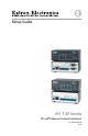
Setup Guide IPL T SF Series IP Link Ethernet Control Interfaces ® 68-1434-01 Rev.
Precautions Safety Instructions • English This symbol is intended to alert the user of important operating and maintenance (servicing) instructions in the literature provided with the equipment. This symbol is intended to alert the user of the presence of uninsulated dangerous voltage within the product’s enclosure that may present a risk of electric shock. Caution Read Instructions • Read and understand all safety and operating instructions before using the equipment.
安全须知 • 中文 警告 这个符号提示用户该设备用户手册中 有重要的操作和维护说明。 电源 • 该 设 备 只 能 使 用 产 品 上 标 明 的 电 源 。 设 备 必须使用有地线的供电系统供电。 第三条线 (地线)是安全设施,不能不用或跳过。 这个符号警告用户该设备机壳内有暴 拔掉电源 • 为安全地从设备拔掉电源,请拔掉所有设备后 或桌面电源的电源线,或任何接到市电系统的电源线。 露的危险电压,有触电危险。 电源线保护 • 妥善布线, 避免被踩踏,或重物挤压。 注意 阅读说明书 • 用 户 使 用 该 设 备 前 必 须 阅 读 并 理 解所有安全和使用说明。 保存说明书 • 用户应保存安全说明书以备将来使 用。 遵守警告 • 用户应遵守产品和用户指南上的所有安 全和操作说明。 维护 • 所有维修必须由认证的维修人员进行。 设备内部 没有用户可以更换的零件。为避免出现触电危险不要自 己试图打开设备盖子维修该设备。 通风孔 • 有些设备机壳上有通风槽或孔,它们是用来防止 机内敏感元件过热。 不要用任何东西挡住通风孔。 锂电池 • 不正确的更换电池会有爆炸的危险。 必须使用 与厂家推荐的相同
Table of Contents Chapter One • Introduction ................................................... 1-1 About this Manual ..................................................................... 1-2 IPL T SF Series Products ............................................................ 1-2 IPL T SF24 ................................................................................. 1-3 IPL T SFI244 .............................................................................. 1-3 Global Configurator . ............
Table of Contents, cont’d All trademarks mentioned in this manual are the properties of their respective owners.
IPL T SF Series Interfaces 1 Chapter One Introduction About this Manual IPL T SF Series Products Global Configurator
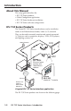
Introduction About this Manual This setup guide describes the • IPL T SF Series products • Global Configurator application • IPL T SF Series hardware installation • IPL T SF Series software configuration IPL T SF Series Products The Extron IPL T SF Series interface boxes can be installed as nodes on an Ethernet-based audio/video (A/V) network. They can be used to remotely monitor and control connected A/V devices such as projectors, displays, VCRs, DVD players, and lighting systems, etc.
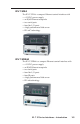
IPL T SF24 The IPL T SF24 is a compact Ethernet control interface with • a 12 VDC power supply • an RJ-45 Ethernet receptacle • two serial ports • four flex I/O ports • a high performance Web server • IP Link® technology IPL T SFI244 The IPL T SFI244 is a compact Ethernet control interface with • a 12 VDC power supply • an RJ-45 Ethernet receptacle • two serial ports • four flex I/O ports • four IR ports • a high performance Web server • IP Link technology IPL T SF Series Interfaces • Introduction 1-3
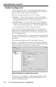
Introduction, cont’d Global Configurator Global Configurator (GC) is a software application that gives users the ability to create a single configuration file of all of the devices on their audio/video (A/V) network. There are two types of devices in an A/V system: Controllers — Control devices that have an IP Link enabled Ethernet port for network connectivity, and serial, relay, I/O, and infrared (IR) ports for A/V device connectivity.
You may configure an IPL T SF Series interface using GC without having the device physically connected to the A/V network. C Use Global Configurator version 2.3 or later. Update all PCs and devices running earlier versions of GC. System requirements The minimum system requirements for the PC on which you install Global Configurator include • Intel Pentium III 1 GHz processor • Microsoft Windows NT SP4, Windows 2000 SP2, or Windows XP SP2 • Microsoft Internet Explorer 6.
Introduction, cont’d 4. Scroll down to the Global Configurator description and click the Install link in the far right column. 5. Follow the remaining system prompts. To install Global Configurator from an Extron Software Products CD if Autorun is not enabled on your PC 1-6 1. Insert the Extron Software Products CD into your drive. 2. From the Windows desktop, open My Computer and select the CD-ROM drive. 3. Double click launch.exe. 4. Wait for the Extron Software Products page to load. 5.
IPL T SF Series Interfaces 2 Chapter Two Hardware Setup Front Panels Rear Panels Power Connection Local Area Network (LAN) Connection Serial Device Connection
Hardware Setup Front Panels The front panels each have a recessed Reset button and the LED indicators described below. a b c d e Power LED — green when power is on f Reset button — a recessed multiple function reset button g IR learning receiver — This smaller infrared receiver "learns" commands from other devices' IR remote controls. See the IR Learner Software's help file for IR learning procedures.
Rear Panels The rear panels have connectors for power, control, signal input, signal output, and indicators as described below. a b Ç É c d Power receptacle — connects the supplied 12 VDC power supply LAN receptacle — RJ-45 receptacle for network connection e LAN activity LED — blinks yellow with LAN activity f LINK LED — green with a network connection COM ports — 3.
Hardware Setup, cont’d Power Connection To connect the power supply: 1. Insert the DC power cord captive screw connector into the power supply receptacle on the rear panel of the interface box. COM 1 POWER 12V .5A MAX LAN COM 2 I/O 1 COM1 2 3 COM2 4 TX RX TX RX Power Supply Receptacle DC Power Cord Captive Screw Connector Ground +12 VDC External Power Supply (12 VDC, 1 A ) AC Power Cord 2.
Local Area Network (LAN) Connection Connect a patch (straight-through) Ethernet cable to the LAN receptacle on the rear panel if you are connecting the interface to a switch, hub, or router on your A/V network. Connect a crossover Ethernet cable to the LAN receptacle on the rear panel if you are connecting the interface directly to a PC. COM 1 POWER LAN COM 2 I/O 12V .
Hardware Setup, cont’d Serial Device Connection There are two types of serial connections: • 9-pin D connectors • Captive screw connectors 9-pin D connectors Connect any A/V device using a serial cable with a 9-pin D connector to either of the COM ports on the rear panel of an IPL T SF24 interface. COM 1 POWER 12V .5A MAX LAN COM1 2 3 IPL T SF24 COM 2 I/O 1 COM2 4 TX RX TX RX COM Ports w/9-pin D Connectors Pinouts for the 9-pin D connectors are shown in the illustration and table below.
Captive screw connectors The IPL T SF24 has two COM ports with captive screw connectors that are common to the two 9-pin D connectors. Only one connector can be used for each COM port. If you use a COM port captive screw connector, its 9-pin D port is not accessible. COM 1 POWER LAN COM 2 I/O 12V .5A MAX 1 COM1 2 3 COM2 4 TX RX IPL T SF24 TX RX COM Ports w/Captive Screw Connectors The IPL T SFI244 has two COM ports, four flex I/O ports, and four IR ports with captive screw connectors.
Hardware Setup, cont’d 2-8 IPL T SF Series Interfaces • Hardware Setup
IPL T SF Series Interfaces 3 Chapter Three Software Setup Creating a Global Configurator Project File Configuring a New Device Building and Uploading a GC File Launching the GlobalViewer® Interface
Software Setup Creating a Global Configurator Project File After you have installed the Global Configurator (GC) application on your PC, follow the steps in this chapter to download device drivers, create a GC project file, configure your IPL T SF Series devices, and launch the GlobalViewer® interface. Step one: download device drivers Software drivers for your audio/video devices are available free from the Extron Web site at www.extron.com. To download device drivers: 3-2 1.
5. Click the Right Arrow (Subscribe) button. 6. Repeat steps 3 through 5 for each type of device you plan to add to your audio/video network. 7. Click the Download button. The Download Complete dialog box opens. 8. Click the Close button. 9. Click OK.
Software Setup, cont’d Step two: create a new project To create a new Global Configurator project file 1. Click File > New. The Start Options dialog box opens. 2. Select Create a New Project. 3. Click OK. The Project Settings dialog box opens (see next page). 3-4 4. Enter the IP address of the first device you will add to your GC project file in the Next Assigned IP Address field. 5. Make the desired date/time selections.
6. Click OK. The Add Device dialog box opens. Step three: add a device There are four ways to launch the Add Device dialog box • Click Ctrl+A. • Click Edit > Add Device... • Click the Add Device icon. When you select Create a Project in the Start Options dialog box and follow the prompts, the Add Device dialog is the second dialog box to open.
Software Setup, cont’d With the Add Device dialog box open: 3-6 1. Select an IPL T SF24 or IPL T SFI244 from the drop-down list. 2. Enter an IP address in the Name/IP Address field (or leave the default address). 3. Enter a unique display name. 4. Click Make this device a GlobalViewer Host (if desired). 5. Click the Advanced button. This opens additional Add Device screen options and changes the Advanced button to read Basic.
9. Click Set. The Auto Configure Successful dialog box is displayed. 10. Click OK. Step four: define the location of the new device Global Configurator allows you to keep track of the devices on your A/V network by creating a custom tree of folders in which you can place and organize your A/V devices. This GlobalViewer Tree can be up to eight levels deep and have multiple folders in each level. To move your newly added device to a Location folder, with the Add Device dialog box still open 1.
Software Setup, cont’d 2. Enter a unique location name for the new folder and keep the new Location folder selected. 3. Click OK. The new device is added to the selected Location folder and the Add Device dialog box closes. Step five: save the new Global Configurator file To save the new GC project file 1. 3-8 Click File > Save or click the Save icon.
If the file has not previously been saved, the Save As dialog box opens. 2. Enter a unique name in the Project Name field. 3. Click the browse button to browse to the desired file location. 4. Click OK. Configuring a New Device Step six: configure contacts The Contact Manager dialog box is used to enter the name, e-mail address, and company name of the network’s contacts. To configure contacts: 1. Click Edit > Contact Manager... 2. Complete the Name, Email, and Company fields. 3. Click Add.
Software Setup, cont’d Step seven: configure e-mail The Email Manager dialog box is used to create custom e-mails that are delivered as directed by the settings in the GC Schedule and Monitor dialog boxes. To create custom e-mails 1. 3-10 Click Edit > Email Manager...
2. Complete the Name, Subject, and Body fields. 3. Click Add. Step eight: assign device drivers The Serial Configuration tab of Global Configurator allows you to assign a device driver to each serial port of the device. To assign a device driver 1. Select a serial port in the IP Link® Tree window. The Serial Configuration tab opens.
Software Setup, cont’d 2. Select a Device Type, Manufacturer, and Version filter. 3. Select an available driver. 4. Click Add Driver. Step nine: set the input/output configuration The Input/Output Configuration tab is used for the Flex I/O ports which can be configured for • Digital In • Digital Out • Analog In To configure a Flex I/O port 1. Select a Flex I/O folder in the IP Link Tree window. 2. Select a Flex I/O Port in the Input/Output Configuration window. 3.
5. Enter a unique open label. 6. Enter a unique close label. 7. Click the Pullup checkbox if desired. 8. Click the Threshold checkbox if desired and set the desired threshold limits.
Software Setup, cont’d If the Flex I/O mode is Digital Output and the mode is Open/Close - 2 Push Button 4. Enter a unique description. 5. Select Open/Close - 2 Push Button. 6. Enter a unique open label. 7. Enter a unique close label. 8. Click the Pullup checkbox if desired. If the Flex I/O mode is Digital Output and the mode is Toggle - 1 Push Button 3-14 4. Enter a unique description. 5. Select Toggle - 1 Push Button. 6. Enter a unique toggle label. 7.
If the Flex I/O mode is Digital Output and the mode is Pulse - 1 Push Button 4. Enter a unique description. 5. Select Pulse - 1 Push Button. 6. Enter a unique pulse label. 7. Enter the desired pulse time. 8. Click the Pullup checkbox if desired.
Software Setup, cont’d If the Flex I/O mode is Analog Input 4. Enter a unique description. 5. Select the analog input options. • Unit Label — Identify the units (ex: "C" for degrees centigrade) that the following values will represent when displayed in the GlobalViewer interface. • Show Values as Voltage — If this radio button is selected, the analog voltage input value to the Flex I/O port is displayed in GlobalViewer and the Custom Value options (below it) will not be active.
Step ten: set the IR configuration The IR Configuration tab is used to configure the IR ports that are present on an IPL T SFI244 device only. To configure an IPL T SFI244 IR port 1. Select an IR port in the IP Link Tree window. 2. Select a device type, manufacturer, and version in the IR Driver Selection area. 3. Select a device driver. 4. Click the Add Driver button. 5. Select the desired driver in Added Driver(s) field. 6.
Software Setup, cont’d Step eleven: set scheduled actions and e-mail deliveries The Schedule tab is used to set scheduled actions and e-mail deliveries. A single schedule can include both actions and e-mail assignments. To schedule an action 1. Click the Schedule tab. 2. Click the Add Schedule button. The Scheduled Actions Wizard dialog box opens. 3-18 3. Enter a unique schedule name. 4. Select the schedule times. 5. Click Next.
6. Click Actions. 7. Select a subject port (device). 8. Select an available option (action). 9. Click Apply Action. To schedule an e-mail delivery 1. Click the Schedule tab. 2. Click the Add Schedule button.
Software Setup, cont’d The Scheduled Actions Wizard dialog box opens. 3. Enter a unique scheduled action name. 4. Select the schedule times. 5. Click Emails. The Add an Email window opens in the right pane. 3-20 6. Select an e-mail message. 7. Select a recipient (contact).
8. Click Apply Email/Contacts. The new e-mail and recipient are now displayed in the left pane. 9. Use the Contact Manager button to create new contacts (if desired). 10. Use the Email Manager button to create new custom e-mails (if desired). 11. Click Done. Step twelve: set monitored conditions The Monitor tab is used to respond with an action or e-mail to a specified condition or event.
Software Setup, cont’d To add a monitored condition: 1. Click the Monitor tab. 2. Click the Add Monitor button. The Monitored Condition Wizard opens.
3. Enter a unique monitored condition name. 4. Click Next. 5. Select Conditions. 6. Select a Subject Port (device). 7. Select an available option. 8. Edit the Name field (if desired). 9. Set the desired condition test parameters (if available). 10. Click Apply Condition. A checkmark appears in the Conditions checkbox. 11. Click Next.
Software Setup, cont’d To add an action 1. Select Actions. 2. Select a subject port (device). 3. Select an available option. 4. Edit the Name field if desired. 5. Select an available command. 6. Click Apply Action. A checkmark appears in the Actions checkbox. 7. Click Next. To add an e-mail notification 3-24 1. Select Emails. 2. Select an e-mail message. 3. Select a contact. 4. Click Apply Email/Contacts. A checkmark appears in the Emails checkbox.
5. Click Done. The dialog box closes. Building and Uploading a GC File Before a Global Configuration (GC) file is active in the GlobalViewer interface, the GC file must be “built” and “uploaded” to a GlobalViewer host device. The “build” process compiles all of the configuration data you have entered into the GC file for each A/V network device. The “upload” process delivers the built (compiled) file to the GlobalViewer host device.
Software Setup, cont’d To initiate a "Build (all)" process 1. Click Build > Build All Configurations... or click the Build All Configurations icon. A Please Wait. Building Configuration(s)... dialog box opens and displays a progress bar while the GC file is being built. Step fourteen: Upload the Global Configurator file When the build process completes, the Upload dialog box opens. 1. Click the Begin button.
2. Click the Test GV System button to view the GlobalViewer host interface. Step fifteen: change device settings (if desired) If for any reason you need to change any of the previously configured settings: 1. Click Tools > Change Device Settings.
Software Setup, cont’d 2. Select a device. 3. Click Settings to open the Settings drop-down listing. 3. Select and change the desired setting(s), for example: Set Mail Server..., Set Gateway..., Set Subnet Mask..., etc. N Use Set Mail Server... in the drop-down listing to identify the local mail server's IP address, domain, and passwords. Launching the GlobalViewer Interface GlobalViewer is a graphical user interface that is generated by Global Configurator (GC).
Step sixteen: launch GlobalViewer To launch GlobalViewer: 1. Open an Internet browser. 2. Enter the IP address of a GlobalViewer host device in the Address field, and press the keyboard's Enter key.
Extron’s Warranty Extron Electronics warrants this product against defects in materials and workmanship for a period of three years from the date of purchase.
Setup Guide Checklist c Chapter 1: Install Global Configurator • Download from www.extron.com, or c • Install from Extron Software Products CD Chapter 2: Make the IPL T SF cable connections. 1. c Power 2. c Local Area Network (LAN) 3. c Serial devices c Chapter 3: Create a Global Configurator (GC) project file. Add and configure a device. Build and upload the GC project file. Launch the GlobalViewer® interface. 1. c Download device drivers. 2. c Create a new Global Configurator project file. 3.