ISM 482 & ISM 182 Integration Scaling Matrix Switchers 68-576-01 Rev.
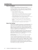
Precautions Safety Instructions • English This symbol is intended to alert the user of important operating and maintenance (servicing) instructions in the literature provided with the equipment. This symbol is intended to alert the user of the presence of uninsulated dangerous voltage within the product's enclosure that may present a risk of electric shock. Warning Power sources • This equipment should be operated only from the power source indicated on the product.
Quick Start — Integration Scaling Matrix Switcher Installation Step 1 Turn off power to the ISM 182 or ISM 482 and the input and output devices, and remove the power cords from them. Step 2 Install four rubber feet on the bottom of the ISM or mount the ISM in a rack. Step 4 Tip Sleeve Cable the switcher for audio input. Each input has a 3.5 mm, 5-pole captive screw connector for balanced or unbalanced stereo or mono audio input.
Quick Start — Integration Scaling Matrix Switcher, cont’d Step 8 Configure the outputs If desired, connect a network WAN or LAN hub, a control system, or computer to the Ethernet RJ-45 port. For connection to a network hub, router, or switch, wire the network interface cable as a straight-through cable. For connection to a computer or control system, wire the network interface cable as a crossover cable. 1. Press Menu > Menu > Next.
Table of Contents Chapter 1 • Introduction ....................................................................................................... 1-1 About this Manual ............................................................................................................. 1-2 About the Switcher ............................................................................................................ 1-2 Features ........................................................................................
Table of Contents, cont’d Blanking submenu ............................................................................................ 3-12 RGB Delay submenu .......................................................................................... 3-12 Auto Imaging and Auto Memories submenu .................................................... 3-13 Enhanced Mode submenu ................................................................................ 3-13 Pixel Phase submenu ................................
Chapter 5 • Switcher Software ......................................................................................... 5-1 Control Software for Windows® .................................................................................. 5-2 Installing the software ...................................................................................................... 5-2 Software operation via Ethernet ......................................................................................
Table of Contents, cont’d Appendix A • Ethernet Connection .............................................................................. A-1 Ethernet Link ........................................................................................................................ A-2 Ethernet connection ......................................................................................................... A-2 Default address ...................................................................................
Integration Scaling Matrix Switcher 1 Chapter One Introduction About this Manual About the Switcher Features
Introduction, cont’d Introduction About this Manual This manual contains installation, configuration, and operating information for the Extron ISM 182 and ISM 482 Integration Scaling Matrix switchers. The ISM 182 and ISM 482 are similar in function and operation; the differences exist in scaling capabilities. In this manual, the terms “switcher” and “ISM” are used interchangeably to refer to either model, except where differences exist, in which case the specific model is noted.
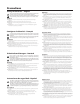
Projector Extron ISM 482 Projector 1 TS 2 TPU OU 1 DVI R OUT 2 R G 32 RS-2 G B B 8 V H/H ET ERN ETH 7 R V H/H 6 LINK ACT V R UTS 5 INP V R G 4 R G 3 R G B 2 R G R G R V H/H B B G V H/H B G G DVD Player RS-232 B 1 V H/H B V H/H V H/H B 8 V H/H B 7 V H/H Hz 5 V H/H 50/60 240 MAX. 100- 1.
Introduction, cont’d Features Inputs — Video inputs — The ISM switches among eight fully-configurable RGB, HDTV component video (ISM 482), component video, S-video, and composite video inputs on five BNC connectors per input. Audio inputs — The ISM switches among eight balanced or unbalanced stereo or mono audio inputs on 5-pole captive screw connectors. Outputs — Video outputs — The ISM outputs individually scaled video signals as RGBHV or RGBS.
Test patterns — The switcher features built-in test patterns to aid in monitor or projector set-up and evaluation. Blue mode — The switcher can be set to output the blue video signal only, to help installers calibrate the monitor or projector. Triple-Action Switching™ (RGB delay) — RGB delay mutes the R, G, and B video planes to blank the screen while the scaler locks to the new sync, so that a noise-filled scramble is not shown on the monitor during the transition.
Introduction, cont’d 1-6 Integration Scaling Matrix Switcher • Introduction
Integration Scaling Matrix Switcher 2 Chapter Two Installation Mounting the Switcher Cabling and Rear Panel Views Configuration
Installation, cont’d Installation Mounting the Switcher Four uninstalled rubber feet are included with the switcher . If you are going to rack mount the switcher, mount it before you cable it (see Rack mounting, below), and do not install the rubber feet. If you are not rack mounting the switcher, see Tabletop placement below. Tabletop placement For tabletop placement, install the self-adhesive rubber feet/pads (provided) onto the four corners of the bottom of the switcher.
Cabling and Rear Panel Views All connectors are on the rear panel (figure 2-2). 2 1 2 3 4 INPUTS 4 OUTPUTS 5 6 8 7 2 1 1 R/R-Y R/R-Y R/R-Y R/R-Y R/R-Y R/R-Y R/R-Y R/R-Y R R G/Y VID G/Y VID G/Y VID G/Y VID G/Y VID G/Y VID G/Y VID G/Y VID G G B/C B-Y B/C B-Y B/C B-Y B/C B-Y B/C B-Y B/C B-Y B/C B-Y B/C B-Y B B H/HV H/HV H/HV H/HV H/HV H/HV H/HV H/HV H/HV H/HV V V V V V 2 RS-232 100- 240 50/60 Hz 1.2A MAX.
Installation, cont’d 3 Input audio connectors — Connect balanced or unbalanced stereo or mono audio to these 3.5 mm, 5-pole captive screw connectors. Connectors are included with the seamless switcher, but you must supply the audio cable. Figure 2-4 shows how to wire a connector for the appropriate input type and impedance level. High impedance is generally over 800 ohms.
Output connections The two Output 1 outputs, consisting of five BNC connectors and a 15-pin HD connector, output the identical video signal and the same sync format. The two Output 2 outputs are also identical to each other. 4 Video output BNC connectors— Connect RGB video displays to these two sets of female BNC connectors. Figure 2-6 shows how to connect the various video formats.
Installation, cont’d Ethernet connection 6 Ethernet port — If desired connect the switcher to an Ethernet LAN or WAN via this RJ-45 connector. Ethernet control allows the operator to control the switcher from a remote location. When connected to an Ethernet LAN or WAN , the switcher can be accessed and operated from a computer running a standard Internet browser. Ethernet connection indicators — The Link and Act LEDs indicate the status of the Ethernet connection.
Wiring the network cable The cable can be terminated as either a patch cable or a crossover cable (figure 2-8) and must be properly terminated for your application: • Patch (straight) cable — Connection of the ISM to an Ethernet hub, router, or switcher that also hosts a controlling computer. • Crossover cable — Direct connection between the ISM and a controlling computer.
Installation, cont’d RS-232 connection 7 Remote port — Connect a host device, such as a computer or touch panel control, to the Integration Seamless Matrix switcher via this 9-pin D connector for serial RS-232 control (figure 2-9).
Integration Scaling Matrix Switcher 3 Chapter Three Operation Front Panel Controls and Indicators Front Panel Operations Optimizing the Video Optimizing the Audio Troubleshooting
Operation, cont’d Operation Front Panel Controls and Indicators All of the switcher’s controls and indicators are on the front panel (figure 3-1). A label window above the input buttons can be labeled with text and/or graphics. The 20 x 4 LCD display indicates the switcher status, menu selections, the data rate, and the status of additional system features.
Outputs buttons and LEDs 2 Output 1 and Output 2 buttons — The Output 1 and Output 2 buttons select output 1 or output 2. Press an output button to select that output and automatically deselect the other output (figure 3-3). Output 1 and 2 LEDs — The Output 1 and Output 2 LEDs indicate the output that is selected (figure 3-3). Only one Output LED can be lit at a time. Only one of the two outputs can be selected at a time.
Operation, cont’d Selecting an input 4 Input selection buttons — The Input 1 through Input 8 buttons select the associated input to scale and display on the selected output(s). Input selection LEDs — The green input LEDs above the input buttons indicate the video selection. The red input LEDs below the input buttons indicate the audio selection. To view the input tied to the unselected output, press the unselected output button. Both outputs’ input selections can also be viewed in the LCD display cycle.
Brightness/Contrast control button — The Brightness/Contrast button selects the display brightness and contrast adjustments. The adjustment range for both brightness and contrast is from 0 to 63. See Picture adjustments in this chapter. Size control button — The Size button selects the display size adjustment. The adjustment range depends on the output resolution selected. See Picture adjustments in this chapter. Center control button — The Center button selects the display centering adjustment.
Operation, cont’d Front Panel Operations The following paragraphs detail the power-up process and then describe the menu system, the picture adjustments, and selection of executive mode. Power Power is automatically applied when the power cord is connected to an AC source. When AC power is applied, the switcher performs a self-test that blinks all of the front panel LEDs and then lights only the LED for the previously selected output and the tied input.
Menu system overview Figure 3-7 shows a flowchart of the main menus in the menu system. Power on Extron Electronics ISM 482 Integration Scaling Matrix 2 sec. Extron Electronics ISM 482 60-425-01 Version x . xx 2 sec. Default Cycle Menu 10 sec. 10 sec. Video & Audio Configuration Menu Output Configuration 10 sec. Menu Advanced Configuration 10 sec. 10 sec.
Operation, cont’d From any menu or submenu, after 10 seconds of inactivity, the ISM saves all adjustment settings and times out to the default LCD display cycle. Video & Audio Configuration menu Figure 3-8 is a flowchart that shows an overview of the Video & Audio Configuration menu and the available settings. Default Cycle Menu 10 sec. Video & Audio Configuration 10 sec. Next Video/Audio Config Next Menu Input #1 Composite Audio #3 Level -12db Menu NOTE The audio is broken away in this example.
Output Configuration menu Figure 3-9 is a flowchart that shows an overview of the Output Configuration menu, the submenus, and the available settings. Default Cycle Menu 10 sec. Video & Audio Configuration Menu 10 sec. Output Configuration Next 10 sec. Output #1 Resolution Next 1280 x 1024 Refresh Rate 60 Hz Output #1 Sync Type Menu Next RGBHV Sync Polarity H Neg V Pos Menu 1 1 Advanced Configuration Output Configuration: OUTPUTS Menu If necessary, select the other output and repeat.
Operation, cont’d 50 Hz 640 x 480 182, 482 182, 482 182, 482 182, 482 800 x 600 182, 482 182, 482 182, 482 182, 482 832 x 624 182, 482 182, 482 182, 482 848 x 480 182, 482 182, 482 852 x 480 182, 482 182, 482 182, 482 182, 482 182, 482 182, 482 1024 x 768* 182, 482 1280 x 768* 1280 x 1024* 56 Hz 60 Hz 482 only 482 only 75 Hz 85 Hz Lock at 50/60 Hz✝ Resolution 482 only 482 only 1360 x 765 482 only 482 only 1365 x 1024 482 only 482 only 482 only 482 only 1400 x 1050 482
Advanced Configuration menu Figure 3-10 is a flowchart that shows an overview of the Advanced Configuration menu, the submenus, and the available settings. Default Cycle Menu 10 sec. Video & Audio Configuration Menu Select a test pattern with the Adjust knob. Select preview/program off/on with the Adjust knob. Output Configuration Menu Next Advanced Configuration Menu User Presets 10 sec. Test Pattern Next Color Bars Out #1 Out # 2 Off Off Select blue mode with the Adjust knob.
Operation, cont’d Test Pattern submenu The Test Pattern submenu lets you select from among several test patterns and assign the selected pattern to an output. The test patterns are helpful when adjusting the connected displays for color, convergence, focus, resolution, contrast, grayscale, and aspect ratio. Use the Adjust knob to select a test pattern. The options are: Color Bars, crosshatch, 4 x 4 crosshatch, gray scale, crop, alternating pixels, film aspect ratios 1.78, 1.85, 2.35, and ramp.
Auto Imaging and Auto Memories submenu The Auto Imaging and Auto Memories submenu provides a means to turn the auto imaging and auto presets features on or off for all input selections. If auto imaging is set to on, the ISM automatically sizes and centers the selected input to fill the screen when a new frequency is input. If auto imaging is set off, the ISM sizes and centers the selected input only when it is commanded using the input button, see Auto imaging an input, earlier in this chapter.
Operation, cont’d User Presets menu Figure 3-11 is a flowchart that shows an overview of the User Presets menu, the Save Preset and Erase Preset submenus, and the available settings. Default Cycle Menu 10 sec. Video & Audio Configuration Menu Output Configuration Menu Advanced Configuration NOTE To save a preset for the second output after saving for the first, start over from the default cycle. Menu 1 Memory OUTPUTS Menu Menu 10 sec.
User presets are recalled using the Input buttons. See Recalling a user preset earlier in this chapter for instructions on recalling a user preset. Erase Preset submenu Select the output with the settings that you want to erase by pressing the desired Output button. Rotate either the Adjust or the Adjust knob while in the Erase Presets submenu to highlight (< >) one of three memory presets to erase or highlight N/A for no preset. Press the Next button to erase the preset.
Operation, cont’d Picture adjustments The picture adjustments allow you to fine tune the image quality of the selected input. When you press one of the Picture Adjustments buttons (Color/Tint, Brightness/Contrast, Size, Center, or Filter) once, the corresponding image adjustment menu for the selected output (lit Output LED) image appears on the LCD screen. Select the other output using the Output buttons to call the image adjustment menu for the other output.
• Color/Tint: Color adjusts within a range from 0 to 127. Tint adjusts within a range from 0 to 255. • Brightness/Contrast: The range for both adjustments is 0 to 63. • Size: Observe the display and turn the Adjust knob to increase or decrease the horizontal size of the image. Turn the Adjust knob to increase or decrease the vertical size of the image. The adjustment range depends on the input rate applied and the output resolution selected.
Operation, cont’d IP information To set up the ISM for operation via its Ethernet port, you need to know and be able to change the IP address. One way to do this is via the IP address and hardware address screen. To access the IP address and hardware address screen, press and hold the Color/Tint and Detail buttons while you apply power to the ISM (figure 3-15). When the ISM is finished intializing, it displays both addresses.
1. If you are using a digital display such as an LCD or DLP projector, use the alternating pixels test pattern as a reference to adjust the phase and dot clock on the display devices. Proceed to step 3. 2. If you are using a CRT display, use the cross hatch test pattern as a reference to converge the display. 3. Set the ISM to output either the crop test pattern for 4:3 video or the appropriate aspect ratio test pattern.
Operation, cont’d Optimizing the Audio Each individual input audio level can be adjusted within a range of -24dB to +9dB, so there are no noticeable volume differences between sources and for the best headroom and signal-to-noise ratio. Adjust the audio gain and attenuation as follows: 1. Connect audio sources to all desired inputs and connect the audio outputs to output devices such as audio players. See Input connections and Output connections, in chapter 2, Installation.
Specific problems The table below shows some common operating problems and their solutions. Problem No image appears. Cause The input signal is incompatible. Solution Connect an input device that is compatible with the ISM. The input is improperly Use the Video & Audio configured. Configuration submenu to select the correct input format. Freeze mode was entered via an SIS command when the image was black. Deactivate freeze mode via an SIS command. The scaled output rate is too high for the display.
Operation, cont’d 3-22 Integration Scaling Matrix Switcher • Operation
Integration Scaling Matrix Switcher 4 Chapter Four Programmer’s Guide RS-232 Link Ethernet Link Symbols Switcher-Initiated Messages Host-to-Switcher Instructions
Programmer’s Guide RS-232 Link The switcher’s rear panel Remote 9-pin D female connector (figure 4-1) can be connected to the RS-232 serial port output of a host device such as a computer running the HyperTerminal utility or a control system. This connection makes software control of the switcher possible.
Ethernet connection The cable can be terminated as either a patch cable or a crossover cable (figure 4-2) and must be properly terminated for your application: • Patch (straight) cable — Connection of the ISM to an Ethernet hub, router, or switcher that also hosts a controlling computer. • Crossover cable — Direct connection between the ISM and a computer. Default address To access the switcher via the Ethernet port, you will need the switcher’s IP address.
Programmer’s Guide Switcher-Initiated Messages When a local event such as power-up or a front panel operation occurs, the switcher responds by sending a message to the host. The switcher-initiated messages are listed in the following pages. The messages are underlined. The switcher does not expect a response from the host, but, for example, the host program might request a new status. Power-up (c) Copyright 2002, Extron Electronics, ISM 482, Vx.
Picture adjustments X2 Col X9 A front panel color adjustment has occurred. adjusted input and X9 is the color variable. X2 is the output number tied to the Tin X10 A front panel tint adjustment has occurred. adjusted input and X10 is the tint variable. X2 X2 X2 is the output number tied to the Brt X11 A front panel color brightness adjustment has occurred. X2 is the output number tied to the adjusted input and X11 is the brightness variable.
Programmer’s Guide, cont’d 1Blu X19 The blue-only mode has been turned on or off for one or both outputs from the front panel. X19 is the on/off status for the either or both outputs. The leading “1” is meaningless. 1Fil X19 The edge enhancement mode has been turned on or off for one or both outputs from the front panel. X19 is the on/off status for the either or both outputs. The leading “1” is meaningless. RGB delay X2 Dly X20 A front panel RGB delay adjustment has occurred.
1Enh X19 The enhanced mode feature has been turned on or off from the front panel for S-video or composite video tied to one or both outputs. X19 is the on/off status for the two outputs. The leading “1” is meaningless. X2 Reconfig The input selected for the feature or a user preset. X2 output has been adjusted using the Auto Image Host-to-Switcher Instructions The switcher accepts SIS commands through its RS-232 port and/or its Ethernet port.
Programmer’s Guide, cont’d Command/response table for SIS commands Command ASCII Command Response (host to switcher) (switcher to host) X1 * X2 ! 1*2! Out X2 •In X1 •All Out2•In1•All Additional description Creating ties Create video and audio tie Example: Create video only tie X1 * X2 & Example: 5*2& Create audio only tie X1 * X2 $ Out X2 •In X1 •RGB Select input X1 to output X2 . Input 1 video and audio selected to output 2. Select video input X1 to output X2 .
Command/response table for SIS commands (cont’d) Command ASCII Command Response (host to switcher) (switcher to host) Additional description Brightness The X2 value specified is the output to which the adjusted input is tied. Set a specific brightness value X2 * X11 Y X2 Brt X11 Increment brightness value Decrement brightness value View the brightness value X2 +Y X2 Brt X11 X2 –Y X2 Brt X11 X2 Y X11 Specify the brightness adjustment. Increase the brightness. Decrease the brightness.
Programmer’s Guide, cont’d Command/response table for SIS commands (cont’d) Command ASCII Command Response (host to switcher) (switcher to host) Set a bottom blanking value Example: X2 * X14 ) 2*5) X2 Blb X14 2Blb5 Increment bottom blanking value Decrement bottom blanking value View the bottom blanking value X2 +) X2 Blb X14 X2 –) X2 Blb X14 Additional description Bottom blanking X2 ) Blank the bottom five lines of the preview output. Increase blanking value 1 line.
Command/response table for SIS commands (cont’d) Command ASCII Command Response (host to switcher) (switcher to host) Auto memories on 1M Aut X3 Auto memories off 0M Aut X3 View auto memories status M Additional description Auto Memories Set the ISM to apply auto memories settings to all inputs as selected. Set the ISM to not apply auto memories settings. Auto memories is X3 (on or off) for all inputs.
Programmer’s Guide, cont’d Command/response table for SIS commands (cont’d) Command ASCII Command Response (host to switcher) (switcher to host) Additional description Executive mode Enable (lock image adjustments) 1X Exe1 Disable 0X Exe0 View the executive mode status Example: X X 0 Lock front panel adjustments; adjust image via RS-232 only. Adjustments & selections can be made from the front panel. Show executive mode status. Executive mode is off.
Command/response table for SIS commands (cont’d) Command ASCII Command Response (host to switcher) (switcher to host) Zap all audio adjustments Zap all ISM settings Esc zA ZapA Zapx Absolute reset Esc ZQQQ Additional description Resets Esc zXXX Zpq Reset all audio levels to 0dB. Reset all settings: All inputs: RGB Ouput: RGBHV 1024x768 @ 60Hz RGB delay: 1.0 sec. (both outputs) Audio level: 0dB Filtering: Horz. = 3, Vert.
Programmer’s Guide, cont’d Command/response table for IP SIS commands Command Set ISM name (location) Read ISM name (location) Set GMT/date ASCII Command Response (host to switcher) (switcher to host) Esc X30 CN Ipn• X30 Esc CN X30 Esc X31 CT Ipt• X32 Additional description The date and time entered should be Greenwich Mean Time (GMT).
Command/response table for special function SIS commands (cont’d) Command ASCII Command Response (host to switcher) (switcher to host) Additional description Blue screen Blue screen (blue & sync output only) X19 *8# Blu X19 Example: 1*8# Blu1 Read blue screen 8# X19 X19 :Output 1/2 Output 1/2 00 = Off/Off 02 = Off/On 01 = On/Off 03 = On/On Blue & sync output for setup.
Programmer’s Guide, cont’d Command/response table for advanced instruction set commands The advanced instruction set consist of four hexadecimal commands for uploading and downloading all or a portion of the switcher’s memory. These commands are for use by knowledgeable programmers, and result in a dump of data from (upload) or to (download) the switcher. Programmers can use the commands to exactly duplicate the settings among switchers with a minimum of effort.
Integration Scaling Matrix Switcher 5 Chapter Five Switcher Software Control Software for Windows® Button-Label Generator
Switcher Software Control Software for Windows® Two software programs accompany the ISM 182 and ISM 482: • The Extron ISS/ISM Control Program (Extron part #29-054-01), which communicates with the switcher via the rear panel Remote port, provides an easy way for you to control the switcher. • The Extron Button-Label Generator, which allows you to design and print a label strip for the switcher’s front panel input selection button window.
Using the control program Many items found in the ISS/ISM Control Program are also accessible via front panel controls and the LCD menus, see chapter 3, Operation, and under SIS control, see chapter 4, Programmer’s Guide. The ISS/ISM Help Program provides information on settings and on how to use the control program itself. 1. To run the control program, double-click the ISS/ISM Control Pgm icon in the Extron Electronics group or folder. The Comm menu appears on the screen (figure 5-1).
Switcher Software, cont’d 5. The Extron ISS/ISM Control Program window (figure 5-3) appears. Figure 5-3 — Windows Control program window 6. If desired, on the task bar click Tools > I/O Configuration to configure the video inputs and outputs in the I/O configuration window (figure 5-4).
7. If desired, on the task bar, click Tools > Audio Settings to set each input’s audio level or attenuation in the Audio Settings window (figure 5-5). Figure 5-5 — Control program Audio Settings window 8. If desired, on the task bar, click Tools > IP Options to set the switcher’s IP parameters in the IP Settings/Options window (figure 5-6).
Switcher Software, cont’d Installing the software The program is included on the same set of 3.5-inch diskettes as the ISS/ISM control program and is installed automatically when you install that program. It can also be downloaded from the Extron Web site (http://www.extron.com). By default, the Windows installation goes in either the C:\ISSISM directory, if installed automatically with the ISS/ISM Control Program or the C:\BUTTONS directory if installed as a stand-alone program.
Integration Scaler Matrix Switcher 6 Chapter Six Ethernet Operation Control Page System Configuration Page File Management Page I/O Configuration Page
Ethernet Operation, cont’d Ethernet Operation The ISM 182 and ISM 482 can each be controlled and operated through its Ethernet port, connected via a LAN or WAN, using a web browser such as Microsoft’s Internet Explorer. The browser’s display of the switcher’s status or operation has the appearance of web pages. This chapter describes the factory-installed HTML pages, which are always available and cannot be erased or overwritten.
7. The switcher checks several possibilities, in the following order, and then responds accordingly: a. Does the address include a specific file name, such as 10.13.156.10/file_name.html? If so, the switcher downloads that HTML page. b. Is there a file in the switcher ’s memory that is named “index.html”? If so, the switcher loads “index.html” as the default startup page. c. If neither of the above conditions is true, the switcher loads the factoryinstalled default startup page, “nortxe_index.
Ethernet Operation, cont’d Control Page On the Control page (figure 6-1), you can select an input to either or both outputs. The Control page also provides facilities to check the frequency of an input and to mute outputs. Access the Control page by clicking the Control tab. Create a tie Select and switch an input to an output as follows: 1.
Freeze the output You can freeze either output by clicking the Output 1 or Output 2 Freeze button. The Freeze button turns blue. When the output is frozen, the input can be removed and the ISM functions as a video store. Click the Freeze button again to toggle freeze mode off. Output a test pattern You can select a test pattern to output on the output 1 and/or output 2 monitors.
Ethernet Operation, cont’d System Configuration Page The ISM downloads the System Configuration page (figure 6-5) when you click the Configuration tab. The screen consists of fields in which you can observe and edit IP administration and system settings. Figure 6-5 — System Configuration page Access to the ISM settings using web control is not password protected. Ensure only knowledgeable and qualified personnel have access to the switcher under Web control.
Administration fields • Ethernet connection to the switcher, either by entering SIS commands (see chapter 4, Programmer’s Guide) or using the Control Program (see chapter 5, Switcher Software) is password protected. • Connection via HTML pages and connection via the RS-232 port are not password protected. On password-protected connections, there are two levels of protection: administrator and user. Administrators have full access to all ISM switching capabilities and editing functions.
Ethernet Operation, cont’d File Management Page To delete files such as HTML pages from the ISM or to upload your own files to the ISM, click the File Management tab. The switcher downloads the file management HTML page (figure 6-6). Figure 6-6 — File Management page To delete a file, check the associated delete check box and click the Delete Files button. Upload your own files as follows: 6-8 1. Click the Browse button. 2. Browse through your system and select the desired file. 3.
I/O Configuration Page You can set up the input configurations and the output format on the I/O Configuration page (figure 6-7). Access the Setup page by clicking the I/O Config tab. Figure 6-7 — I/O Configuration page Input configuration You can specify the format of each input. The available formats are RGB, RGBcvS (identified as RGBcS in the drop box), YUVi, YUVp, Betacam 50, Betacam 60, HDTV, S-video, and composite video. Specify the input format as follows: 1.
Ethernet Operation, cont’d Output resolution, rate, sync format, and polarity The ISM 482 scales the input up or down to any 1 of 40 output resolutions and rates. The ISM 182 scales the inputs to 1 of 20 resolutions and rates. Either switcher outputs the scaled video as RGBHV or RGBS, with user-selectable polarity, via either the program or preview connectors. The table below shows the resolutions and rates available on the ISM 482 and ISM 182.
Output resolution Select the output resolution as follows: 1. Click the resolution field. A drop down scroll box appears (figure 6-9). Figure 6-9 — Resolution scroll box 2. Click and drag on either the slider or click the scroll up ( ) or scroll down ( ) buttons until the desired rate is visible. 3. Click the desired output. 4. Click the Submit button. Output rate Select the output rate as follows: 1. Click the Rate field. A drop down box appears (figure 6-10). Figure 6-10 — Rate @ drop box 2.
Ethernet Operation, cont’d Output format Select between separate horizontal (H) and vertical (V) sync or composite (S) sync as follows: 1. Click the Type field. A drop down box appears (figure 6-11). Figure 6-11 — Type drop box 2. Click the desired sync type. 3. Click the Submit button. Output polarity Select the output polarity as follows: 1. Click the Polarity field. A drop down box appears (figure 6-12). Figure 6-12 — Polarity drop box 6-12 2. Click the desired output sync polarity. 3.
Integration Scaling Matrix Switcher A Appendix A Ethernet Connection Ethernet Link
Ethernet Connection, cont’d Ethernet Link The rear panel Ethernet connector (figure A-1) on the ISM switcher can be connected to an Ethernet LAN or WAN. This connection makes SIS control of the switcher possible using a computer connected to the same LAN.
Default address To access the ISM switcher via the Ethernet port, you will need the Extron ISM IP address. If the address has been changed to an address comprised of words and characters, the actual numeric IP address can be determined using the Ping utility. If the address has not been changed, the factory-specified default is 192.168.254.254. Ping can also be used to test the Ethernet link to the ISM. Ping to determine the switcher’s IP address The Microsoft Ping utility is available at the DOS prompt.
Ethernet Connection, cont’d Connect as a Telnet client The Microsoft Telnet utility is available from the DOS prompt. Telnet allows you to input SIS commands to the ISM from the PC via the Ethernet link and the LAN. Access the DOS prompt and start Telnet as follows: 1. Click on Start > Run. 2. At the Open prompt, type command. 3. Click on the OK button. 4. At the DOS prompt, type telnet and press [Enter]. The computer returns a display similar to figure A-3. Microsoft (R) windows 2000 (TM) Version 5.
Escape character and Esc key When Telnet is first started, the utility advises that the Escape character is ‘Ctrl+]’. Many SIS commands include the keyboard Esc key. Consequently, some confusion may exist between the Escape character and the Escape key. The Telnet Escape character is a key combination, the Ctrl key and the ] key pressed simultaneously, that returns you to the Telnet prompt while leaving the connection to the ISM intact. The Escape key is the Esc key on the computer keyboard.
Ethernet Connection, cont’d A-6 Integration Scaling Matrix Switcher • Ethernet Connection
Integration Scaling Matrix Switcher B Appendix B Reference Information Specifications Part Numbers Firmware Upgrade Installation Button Labels
Reference Information Specifications Video Routing .......................................... 8 x 2 matrix Video input Number/signal type ................... 8 RGBHV, RGBS, RGsB, RGBcvS, component video, S-video, composite video Connectors ................................... 8 x 5 female BNC Nominal level ............................... 1V p-p for Y of component video and S-video, and for composite video 0.7V p-p for RGB 0.
Audio Routing .......................................... Gain ................................................ Frequency response .................... THD + Noise ................................. S/N ............................................... Crosstalk ....................................... Stereo channel separation .......... CMRR ............................................ 8 x 2 stereo matrix Unbalanced output: 0dB; balanced output: +6dB 20 Hz to 20 kHz, ±0.05dB 0.
Reference Information, cont’d DIM weight USA/Canada .................... International ..................... Vibration ....................................... Listings .......................................... Compliances ................................. MTBF ............................................. Warranty ....................................... 18 lbs (8.2 kg) 21 lbs (9.
BNC-4 Mini HR Cable Part # BNC-4 Mini HR bulk, 500’ 22-032-02 BNC-4 Mini HR bulk, 1000’ 22-032-03 BNC-5 Mini HR Cable BNC-5 Mini HR bulk, 500’ 22-020-02 BNC-5 Mini HR bulk, 1000’ 22-020-03 Plenum BNC-5 Mini HR Cable Plenum BNC-5 Mini HR bulk, 500’ 22-103-02 Plenum BNC-5 Mini HR bulk, 1000’ 22-103-03 Assorted connectors BNC connectors BNC Mini HR crimp connectors, qty. 50 100-074-51 SHR male crimp connectors, qty. 50 100-075-51 BNC bulkhead connectors, qty.
Reference Information, cont’d Firmware Upgrade Installation In some cases the ISM’s firmware may require replacement with an updated version. There are nine user-replaceable firmware chips, U1, U2, and U6 on the front panel circuit board and U98, U99, U100, U101, U102, and U103 on the main circuit board. The U-numbers are printed on the circuit boards. We recommend that you send the unit in to Extron for service and updates. • Chip set U1 and U2 are replaced as a pair. • Chip U6 is replaced alone.
Lift cover straight up. Remove (16) screws. Remove top two front panel screws. U102 U103 U6 U1 U2 U98 U99 Connect to J8 and J13. J13 J8 B 8 H/HV 7 R H/HV 6 V R TS 5 INPU V R G 4 R G 3 R G B 2 R G B 1 R G R V H/H B G B G V H/H B G V H/H B V H/H V H/H B 8 V H/H B 7 V H/H U100 U101 Hz 100 6 5 V H/H /60 50 X. 0 MA - 24 A 1.2 4 3 Extron ISM 482 2 1 Switcher Figure B-1 — Removing the ISM cover 8.
Reference Information, cont’d 13. Secure the cover in place with the screws that were removed in steps 3 and 4. 14. Rack mount the switcher if desired and reconnect all cables. Button Labels Eight sets of button labels are provided on the next page. Feel free to cut them out of the manual, write the applicable button information in each button area, and place them in the switcher’s label window.
Integration Scaling Matrix Switcher • Reference Information B-9
Reference Information, cont’d B-10 Integration Scaling Matrix Switcher • Reference Information
FCC Class B Notice This equipment has been tested and found to comply with the limits for a Class B digital device, pursuant to part 15 of the FCC Rules. These limits are designed to provide reasonable protection against harmful interference in a residential installation. This equipment generates, uses and can radiate radio frequency energy and, if not installed and used in accordance with the instructions, may cause harmful interference to radio communications.
www.extron.com Extron Electronics, USA Extron Electronics, Europe Extron Electronics, Asia Extron Electronics, Japan 1230 South Lewis Street Anaheim, CA 92805 USA 714.491.1500 Fax 714.491.1517 Beeldschermweg 6C 3821 AH Amersfoort The Netherlands +31.33.453.4040 Fax +31.33.453.4050 135 Joo Seng Road, #04-01 PM Industrial Building Singapore 368363 +65.6383.4400 Fax +65.6383.4664 Daisan DMJ Building 6F 3-9-1 Kudan Minami Chiyoda-ku, Tokyo 102-0074 Japan +81.3.3511.7655 Fax +81.3.3511.