
- Extron Electronics Hub/Switch Installation Guide

Ethernet Connection, cont’d
Integration Scaling Matrix Switcher • Ethernet ConnectionA-2
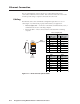
The rear panel Ethernet connector (figure A-1) on the ISM switcher can be
connected to an Ethernet LAN or WAN. This connection makes SIS control of the
switcher possible using a computer connected to the same LAN.
Cabling
The Ethernet cables can be terminated as straight-through cables or crossover
cables (figure A-1) and must be properly terminated for your application:
• Patch (straight) cable — Connection of the ISM to an Ethernet hub, router, or
switcher that also hosts a controlling computer
• Crossover cable — Direct connection between the ISM and a controlling
computer
Patch (straight) cable
Side 1 Side 2
Pin Wire color Pin Wire color
1 White-orange 1 White-orange
2 Orange 2 Orange
3 White-green 3 White-green
4 Blue 4 Blue
5 White-blue 5 White-blue
6 Green 6 Green
7 White-brown 7 White-brown
8 Brown 8 Brown
Crossover cable
Side 1 Side 2
Pin Wire color Pin Wire color
1 White-orange 1 White-green
2 Orange 2 Green
3 White-green 3 White-orange
4 Blue 4 Blue
5 White-blue 5 White-blue
6 Green 6 Orange
7 White-brown 7 White-brown
8 Brown 8 Brown
Side
12345678
Insert
twisted
pair wires.
Pins:
RJ-45
Connector
Figure A-1 — RJ-45 connector pinout tables