User Guide Scaling Matrix Switchers ISM 482 Integrated Scaling Matrix Switcher No Photo Available yet 68-576-01 Rev.
Safety Instructions Safety Instructions • English WARNING: This symbol, , when used on the product, is intended to alert the user of the presence of uninsulated dangerous voltage within the product’s enclosure that may present a risk of electric shock. ATTENTION: This symbol, , when used on the product, is intended to alert the user of important operating and maintenance (servicing) instructions in the literature provided with the equipment.
FCC Class A Notice This equipment has been tested and found to comply with the limits for a Class A digital device, pursuant to part 15 of the FCC rules. The Class A limits provide reasonable protection against harmful interference when the equipment is operated in a commercial environment. This equipment generates, uses, and can radiate radio frequency energy and, if not installed and used in accordance with the instruction manual, may cause harmful interference to radio communications.
Software Commands Commands are written in the fonts shown here: ^AR Merge Scene,,Op1 scene 1,1 ^B 51 ^W^C [01] R 0004 00300 00400 00800 00600 [02] 35 [17] [03] E X! *X1@* X1%* X1** X1^ CE} NOTE: For commands and examples of computer or device responses mentioned in this guide, the character “0” is used for the number zero and “O” is the capital letter “o.” Computer responses and directory paths that do not have variables are written in the font shown here: Reply from 208.132.180.
Contents Introduction............................................................ 1 About This Guide................................................. 1 About the Switcher.............................................. 1 Features.............................................................. 3 Installation............................................................... 5 Mounting the Switcher......................................... 5 Tabletop Placement.........................................
Switcher Software............................................... 47 Maintenance and Modifications...................... 64 Control Software for Windows®...............................................47 Installing the Software.................................... 47 Software Operation via Ethernet.................... 48 Using the Control Program............................ 49 Using the Help Program................................ 51 Button-Label Generator.....................................
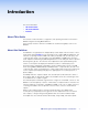
Introduction This section describes: • About This Guide • About the Switcher • Features About This Guide This manual contains installation, configuration, and operating information for the Extron ISM 482 Integration Scaling Matrix Switcher. In this manual, the terms “switcher” and “ISM” are used interchangeably to refer to the ISM 482. About the Switcher The ISM 482 is an eight-input, two-independently-scaled-output, video and stereo or mono audio matrix switcher.
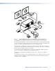
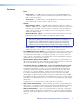
Projector Extron ISM 482 Projector 1 TS 2 TPU OU 1 DVI R OUT 2 R G 232 RS- G B B 8 7 6 DVD Player G LINK ACT Control System (RS-232) V H/H V H/H B B V H/H B V H/H V H/H B 8 V H/H B 7 V H/H Hz LAN/WAN Network/ Internet 6 5 V H/H 50/60 240 MAX. 100- 1.2A ET B B G G ERN B G R G ETH V G G G R R V H/H V R R R 2 1 V H/H R R UTS 5 INP 4 3 4 3 2 1 Codec Extron RGB 112xi VCR Laptop Figure 1.
Features • • Inputs • Video inputs — The ISM switches among eight fully-configurable RGB, HDTV component video, component video, S-video, and composite video inputs on five BNC connectors per input. • Audio inputs — The ISM switches among eight balanced or unbalanced stereo or mono audio inputs on 5-pole captive screw connectors. Outputs • Standard video outputs — The ISM outputs individually scaled video signals as RGBHV or RGBS. Two sets of BNC connectors and two 15-pin HD connectors are provided.
• Ethernet port — Supports connection to an Ethernet LAN so that the switcher can be accessed and operated from anywhere in the world with a computer using a standard Internet browser. • Quad-standard video decoder — The switcher uses a digital, four-line adaptive comb filter that can decode NTSC 3.58, NTSC 4.43, PAL, and SECAM. • Test patterns — The switcher features built-in test patterns to aid in monitor or projector setup and evaluation.
Installation This section describes: • Mounting the Switcher • Cabling and Rear Panel Views • Configuration Mounting the Switcher Four uninstalled rubber feet are included with the switcher. If you are going to rack mount the switcher, mount it before you cable it (see “Rack Mounting,” below), and do not install the rubber feet. If you are not rack mounting the switcher, see “Tabletop Pacement,” below.
ST JU AD 2 48 X ISMMATRI G IN ER FILT N IO NT CE XT SIZE 1 VIDE R/ LO CO NT TI NE NU ME O UT TP OU 8 S UT INP T/ BRNT CO AL SC AT GR TE IN ER 7 6 O AU 5 2 DI 8 4 7 3 6 2 5 1 4 K AC BL 3 2 1 TE MU Figure 2. Mounting the Switcher Cabling and Rear Panel Views All connectors are on the rear panel (see figure 3).
R/R-Y R/R-Y R/R-Y R/R-Y R/R-Y G/Y VID G/Y VID G/Y VID G/Y VID G/Y VID B/C B-Y B/C B-Y B/C B-Y B/C B-Y B/C B-Y H/HV H/HV H/HV H/HV H/HV V RGBHV Video V RGBS or RGBcvS Video Figure 4. c V V RGsB or Component Video S-Video V Composite Video Connections for Various Input Video Formats Input audio connectors — Connect balanced or unbalanced stereo or mono audio sources to these 3.5 mm, 5-pole captive screw connectors.
Standard Output Connections NOTE: The two Output 1 outputs, consisting of five BNC connectors and a 15‑pin HD connector, output the identical video signal and the same sync format. The two Output 2 outputs are also identical to each other. d Video output BNC connectors — Connect RGB video displays to these two sets of female BNC connectors. Figure 7 shows how to connect the various video formats. R R G G B B H/HV H/HV V V RGBHV Video RGBS Video Figure 7.
Optional Output Connection f DVI output connector (optional) — If the optional DVI output card is installed, connect a DVI/DFP-compatible video display to this DVI connector. This connector outputs the image selected for output 1 only. NOTE: For output resolutions with less than 1024 pixels horizontally, the optional DVI output’s true horizontal resolution is limited to 1024 pixels.
Wiring the network cable The cable can be terminated as either a patch cable or a crossover cable (see figure 9) and must be properly terminated for your application: • Patch (straight) cable — Connection of the ISM to an Ethernet hub, router, or switcher that also hosts a controlling computer • Crossover cable — Direct connection between the ISM and a controlling computer Crossover Cable Pins: 12345678 Pin Insert Twisted Pair Wires Straight-through Cable End 2 Wire color Pin End 1 Wire color End
Operation This section describes: • Front Panel Controls and Indicators • Front Panel Operations • Optimizing the Video • Optimizing the Audio • Troubleshooting Front Panel Controls and Indicators All of the switcher’s controls and indicators are on the front panel (see figure 11). A label window above the input buttons can be labeled with text and/or graphics. The 20 x 4 LCD display indicates the switcher status, menu selections, the data rate, and the status of additional system features.
Video/Audio Selection Button and LEDs a Video/Audio button — The Video/Audio button selects video, audio, or video and audio for creating ties. If neither is selected, no ties can be created. Video and Audio LEDs — The green Video LED and red Audio LED indicate whether video, audio, video and audio, or neither will be selected using the Input buttons and indicated by the Input LEDs (d).
Input Buttons, LEDs, and Label Window Front panel input label window c Input label panel — This translucent panel can be removed and replaced to insert a label behind the panel. To remove the panel, insert the Phillips-head end of an Extron tweeker or small Phillips-head screwdriver into the hole in one end of the panel, and gently slide the tab on the edge of the panel out of the recess in the switcher housing.
Auto imaging an input The auto imaging feature automatically sizes and centers the selected input to fill the screen. Initiate the auto imaging feature for a specific input by pressing and holding the appropriate input button until the LCD displays the message Auto Image Input #n, releasing the input button, and then pressing and releasing the input button again. The LCD displays AutoSizing and Centering Please Wait... until the operation is complete.
LCD Display g Status display — The 20-column by 4-line LCD displays configuration menus and status information (see “Front Panel Operations,” below, for details). Menu Control Buttons h Menu button — The Menu button enters and moves through the main menu system in the ISM (see “Front Panel Operations,” below, for details). Next button — The Next button steps through the submenus in the ISM menu system (see “Front Panel Operations,” below, for details).
Menu System Overview Figure 17 shows a flowchart of the main menus in the menu system. Power on Extron Electronics ISM 482 Integration Scaling Matrix 2 sec. Extron Electronics ISM 482 60-425-01 Version x.xx 2 sec. Default Cycle Menu 10 sec. Video & Audio Configuration Menu 10 sec. Output Configuration 10 sec. Menu Advanced Configuration 10 sec. User Presets Menu Menu 10 sec. Exit Menu Press Next to Exit Next Menu Figure 17.
Video & Audio Configuration menu Figure 18 is a flowchart that shows an overview of the Video & Audio Configuration menu and the available settings. Default Cycle Menu 10 sec. Video & Audio Configuration 10 sec. Next Video/Audio Config Next Menu Input #1 Composite Audio #3 Level -12db Menu NOTE: The audio is broken away in this example. 1 Input Configuration: Input Configuration: Select an input to configure by pressing an Input button.
Output Configuration menu Figure 19 is a flowchart that shows an overview of the Output Configuration menu, the submenus, and the available settings. Default Cycle Menu 10 sec. Video & Audio Configuration Menu Output Configuration 10 sec. 10 sec.
Resolution 640 x 480 800 x 600 50 Hz 56 Hz • • 832 x 624 848 x 480 852 x 480 1024 x 768* 1280 x 768* 1200 x 800* 1280 x 1024* • • • • 1360 x 765* 1365 x 768* • 1366 x 768* 1365 x 1024 1400 x 1050* 576p HDTV* • • 720p* HDTV @ 60 Hz only 1080p HDTV @ 60 Hz only 1080i HDTV • • 60 Hz 75 Hz • • • • • • • • • • • • • • • • • 85 Hz • • Lock at 50/60 Hz✝ Actual DVI output • • • • • • • • 1024 x 480 1024 x 600 1024 x 624 1024 x 480 1024 x 480 1024 x 768 1280 x 768 1200 x 800 1280 x 1024 • • •
The display or projector may require a particular combination of horizontal (H) and vertical (V) sync signal polarities. Select the appropriate combination of positive or negative H and V sync for the selected output by rotating the Adjust knob. If you need to set the sync type and polarity on the other output, press the other output button. You do not need to exit this submenu.
Test Pattern submenu The Test Pattern submenu lets you select from among several test patterns and assign the selected pattern to an output. The test patterns are helpful when adjusting the connected displays for color, convergence, focus, resolution, contrast, grayscale, and aspect ratio. Use the Adjust knob to select a test pattern. The options are: Color Bars, crosshatch, 4 x 4 crosshatch, grayscale, crop, alternating pixels, film aspect ratios 1.78, 1.85, 2.35, and ramp.
Auto Imaging and Auto Memories submenu The Auto Imaging and Auto Memories menu provides a means to turn the auto imaging and auto presets features on or off globally. If auto imaging is set to on, the ISM automatically sizes and centers the selected input to fill the screen when a new frequency is input. If auto imaging is set to off, the ISM automatically sizes and centers the selected input only when it is commanded using the input button (see Auto imaging an input on page 14).
User Presets menu Figure 21 is a flowchart that shows an overview of the User Presets menu, the Save Preset and Erase Preset submenus, and the available settings. Default Cycle Menu 10 sec. Video & Audio Configuration Menu Output Configuration Menu NOTE: To save a preset for the second output after saving the preset for the first, start over from the default cycle. Advanced Configuration Menu User Presets Menu 10 sec. 1 2 If necessary, select the unselected output. 1 2 10 sec.
User presets are recalled using the Input buttons. See Recalling a user preset, on page 13, for instructions on recalling a user preset. Erase Preset submenu Select the output with the settings that you want to erase by pressing the desired Output button. Rotate either the Adjust or the Adjust knob while the Erase Presets submenu is active to highlight (< >) one of three memory presets to erase or highlight N/A for no preset. Press the Next button to erase the preset.
Picture Adjustments The picture adjustments allow you to fine tune the image quality of the selected input. When you press one of the Picture Adjustments buttons (Color/Tint, Brightness/Contrast, Size, Center, or Filter) once, the corresponding image adjustment menu for the selected output (lit Output LED) image appears on the LCD screen. Select the other output using the Output buttons to call the image adjustment menu for the other output.
3. Rotate the Adjust knob or Adjust knob to vary the settings within the following adjustment ranges: NOTE: The Adjust knobs have no mechanical limits to their rotation. • Color/Tint: Color adjusts within a range of 0 to 127. Tint adjusts within a range of 0 to 255. • Brightness/Contrast: The range for both adjustments is 0 to 63. • Size: Observe the display and turn the Adjust knob to increase or decrease the horizontal size of the image.
IP Information To set up the ISM for operation via its Ethernet port, you need to know and be able to change the IP address. One way to do this is via the IP address and hardware address screen. To access the IP address and hardware address screen, press and hold the Color/Tint and Detail buttons while you apply power to the ISM (see figure 25). When the ISM is finished initializing, it displays both addresses. Press and hold both buttons simultaneously while applying power.
Optimizing the Video Perform the following steps, in sequence, after you have installed the ISM. This procedure will help you to configure the switcher for the best settings for your display environment. In a multi-screen environment, perform this procedure for each display. See Advanced Configuration menu on page 20, to select and output a test pattern and to select and output blue-only video. See Picture Adjustments on page 25, to make adjustments to the picture quality.
Setting up a DVD source To get the best results when using a DVD as a video source, Extron recommends that the DVD player itself be set up to output an aspect ratio of 16:9 and not 4:3. Because all DVDs are mastered as 16:9, having them set up for anything else causes the player to internally scale and compress the signal. The DVD player’s scaling and compression defeats the advantage of having 3-2 pulldown detection in the ISM.
General Checks 1. Ensure that all devices are plugged in and powered on. The switcher is receiving power if the LCD is displaying the default display cycle. 2. Ensure an active input is selected on the switcher. 3. Ensure that the proper signal format is supplied. 4. Check the cabling and make corrections as necessary. 5. Call the Extron S3 Sales & Technical Support Hotline if necessary. Specific Problems The table below shows some common operating problems and their solutions.
Programming Guide This section describes: • RS-232 Link • Ethernet Link • Symbols • Switcher-Initiated Messages • Host-to-Switcher Instructions • Switcher Error Responses • Using the Command and Response Table RS-232 Link The switcher’s rear panel Remote port 9-pin D female connector (see figure 26) can be connected to the RS-232 serial port output of a host device, such as a computer running the HyperTerminal utility or a control system.
Ethernet Link The rear panel Ethernet connector on the switcher can be connected to the an Ethernet LAN or WAN (see figure 27). This connection makes SIS control of the switcher possible using a computer connected to the same LAN or WAN.
Symbols Symbols (X` values), defined below, are used throughout the discussions of the switcherinitiated messages that begins on the next page and the command/response table that begins on page 37. The symbols represent variables in the switcher-initiated messages and the command/response table fields.
Switcher-Initiated Messages When a local event such as power-up or a front panel operation occurs, the switcher responds by sending a message to the host. The switcher-initiated messages are listed in the following pages. The messages are underlined. The switcher does not expect a response from the host; but, for example, the host program might request a new status. Power-up (c) Copyright 20nn, Extron Electronics, ISM 482 Vx.xx] The switcher initiates the copyright message when it is first powered on. Vx.
X@BrtX1!] A front panel color brightness adjustment has occurred. X@ is the output number tied to the adjusted input and X1! is the brightness variable. X@ConX1!] A front panel contrast adjustment has occurred. X@ is the output number tied to the adjusted input and X1! is the contrast variable. X@HszX1@] A front panel horizontal size adjustment has occurred. X@ is the output number and X1@ is the size variable. X@VszX!@] A front panel vertical size adjustment has occurred.
RGB Delay X@DlyX2)] A front panel RGB delay adjustment has occurred. X@ is output number and X2) is the delay value, in 0.01 second steps. X2) can be as much as 50 = 5.0 seconds. Test Pattern TstX1(*X2!] A test pattern has been turned on or off from the front panel for one or both outputs. X1( is the on/off status for the two outputs and X2! is the test pattern selected. Audio Gain and Attenuation X!AudX2@] A front panel audio input level adjustment has occurred.
Host-to-Switcher Instructions The switcher accepts SIS commands through its RS-232 port and/or its Ethernet port. SIS commands consist of one or more characters per command field. They do not require any special characters to begin or end the command character sequence. Each switcher response to an SIS command ends with a carriage return and a line feed (CR/LF = ]), which signals the end of the response character string. A string is one or more characters.
Command and Response Table for SIS Commands SIS Command Response (Host to Unit) (Unit to Host) X@*X!! Select input X! to output X@. Tie input 2 video and audio to output 2. X@*X!$ OutX@•InX!•All] Out1•In2•All] OutX@•InX!•RGB] Out2•In5•RGB] OutX@•InX!•Aud] View video and audio tie X@! X!] View video tie View audio tie X@& X@$ X!] X!] Video and audio input X! are tied to output X@. Video input X! is tied to output X@. Audio input X! is tied to output X@.
Command Function SIS Command Response (Host to Unit) (Unit to Host) Additional description Tint NOTES: • • Tint adjustments are available only for S-video and composite video inputs. The X@ value specified is the output to which the adjusted input is switched. Set a specific tint value Increment tint value Decrement tint value View the tint value X@*X1)T X@+T X@–T X@T X@TinX1)] X@TinX1)] X@TinX1)] X1)] Specify the tint adjustment. Increase the tint setting by one.
Command and Response Table for SIS Commands (continued) SIS Command Response (Host to Unit) (Unit to Host) X@*X1$( X@BltX1$] 1Blt2] X@BltX1$] X@BltX1$] X@BltX1$] Blank the top two lines of output 1. Increase blanking value 1 line. Decrease blanking value 1 line. X@+) X@–) X@) X@BlbX1$] 2Blb5] X@BlbX1$] X@BlbX1$] X@BlbX1$] Blank the bottom five lines of output 2. Increase blanking value 1 line. Decrease blanking value 1 line.
Command and Response Table for SIS Commands (continued) Command Function SIS Command Response (Host to Unit) (Unit to Host) Additional description Detail filter (S-video and composite video inputs) NOTES: • Composite and S-video inputs support a single detail filter only, rather than separate horizontal and vertical filters. To apply a detail filter to the scaled output when the input is composite video or S-video, use the same command as the horizontal filter (D) with the X1& variable.
Command and Response Table for SIS Commands (continued) Command Function SIS Command Response (Host to Unit) (Unit to Host) Additional description Set audio gain and attenuation NOTE: The set gain (G) and set attenuation command (g) are case sensitive. The increment, decrement and view commands are not case sensitive. Set gain Example: Set attenuation Increment level Decrement level View audio level Example: X!*X2#G Set gain for input X! to X2# dB. Set gain for input 4 to 3 dB.
Command and Response Table for SIS Commands (continued) Command Function SIS Command Response (Host to Unit) (Unit to Host) Q N x.xx] 60-423-01] (See below) Additional description Information requests Query firmware version number Request part number Request general information X@I Show the controller firmware version. Show the part number of the ISM. Show the status of the ISM.
Command and Response Table for IP SIS Commands Symbol definitions X3) = ISM name (Up to 240 alphanumeric characters) NOTE: The following characters are invalid or not recommended in the name: {space} + ~ , @ = ` [ ] { } < > ‘ “ ” ; : | \ and ?.
Command and Response Table for Special Function SIS Commands The syntax for setting a special function is X/*X?# where X/ is the value or variable (such as 35 in the first example below), X/ is the function number (such as “set RGB delay” in the first example below), and # is the execute command. To view the setting of a function, use X? # where X? is the function number.
Command and Response Table for Advanced Instruction Set Commands The advanced instruction set consists of four hexadecimal commands for uploading and downloading all or a portion of the memory of the switcher. These commands are for use by knowledgeable programmers, and result in a dump of data from (upload) or to (download) the switcher. Programmers can use the commands to exactly duplicate the settings among switchers with a minimum of effort.
Switcher Software This section describes • Control Software for Windows® • Button-Label Generator Control Software for Windows® The Windows-based Extron ISSISM Control Program communicates with the switcher via the Ethernet LAN port or the rear panel Remote RS-232/RS-422 port to provide an easy way to set up and operate the switcher. The program is compatible with Windows 2000 and Windows XP. Updates to these programs can be downloaded from the Extron Web site (http://www.extron.com).
3. Scroll to the desired program and click Install (see figure 29). Figure 29. Software Installation 4. Follow the on-screen instructions.
Using the Control Program Many items found in the ISS/ISM Control Program are also accessible via front panel controls and the LCD menus (see the Operation section, starting on page 15), and under SIS control (see the Programming Guide section, starting on page 38). The ISS/ISM Help Program provides information on settings and on how to use the control program, itself. 1. To run the control program, click Start > Programs > Extron Electronics > ISSISM. The Comm menu appears on the screen (see figure 30).
Figure 32. Windows Control Program Window 5. If desired, on the task bar click Tools > I/O Configuration to configure the video inputs and outputs in the I/O configuration window (see figure 33). Figure 33. Control Program I/O Configuration Window 6. If desired, on the task bar, click Tools > Audio Settings to set each input’s audio level or attenuation in the Audio Settings window (see figure 34). Figure 34.
7. If desired, on the task bar, click Tools > IP Options to set the switcher’s IP parameters in the IP Settings/Options window (see figure 35). Figure 35. Control Program IP Setting/Options Window NOTE: When the control program is connected to the switcher via the RS-232 link, the Administrator and User password fields are not masked. If a password has been inadvertently changed to an unknown value, you can look up and, if desired, change a password in this window without knowing the current password.
Using the Software 1. To run the Button-Label Generator program, click Start > Programs > Extron Electronics > Button-Label Generator. Extron’s Button-Label Generator window appears (see figure 36). 2. Under Systems selection, choose ISS 408/ISM 482. This selection creates the correctly sized labels for the ISM’s label strip. The button label editing area changes to reflect the number and arrangement of buttons on the device. Figure 36. The Extron Button-Label Generator Window 3.
HTML Operation This section describes • Loading the Startup (Control) Page • Control Page • System Configuration Page • File Management Page • I/O Configuration Page The ISM 482 can be controlled and operated through its Ethernet port, connected via a LAN or WAN, using a Web browser such as the Microsoft® Internet Explorer®. This chapter describes the factory-installed HTML pages, which are always available and cannot be erased or overwritten.
Figure 37. Enter Network Password Page NOTE: A User Name entry is not required. 6. Click in the Password field and type in the appropriate administrator or user password. 7. Click the OK button. The switcher checks several possibilities, in the following order, and then responds accordingly. a. Does the address include a specific file name, such as 10.13.156.10/file_name.html? If so, the switcher downloads that HTML page. b. Is there a file in the switcher’s memory that is named “index.
Control Page On the Control page (see figure 38), you can select an input to either or both outputs. The Control page also provides facilities to check the frequency of an input and to mute outputs. Access the Control page by clicking the Control tab. Creating a Tie Select and switch an input to an output as follows: 1. Click the Video/Audio, Video, or Audio button to select both the video and audio planes, the video plane only, or the audio plane only for switching (audio follow or audio breakaway). 2.
Freezing the Output You can freeze either output by clicking the Output 1 or Output 2 Freeze button. The Freeze button turns blue. When the output is frozen, the input source can be removed and the ISM functions as a video store. Click the Freeze button again to toggle freeze mode off. Outputting a Test Pattern You can select a test pattern to output on the output 1 and/or output 2 monitors.
System Configuration Page The ISM downloads the System Configuration page (see figure 41) when you click the Configuration tab. The screen consists of fields in which you can observe and edit IP administration and system settings. Figure 41. System Configuration Page NOTE: Access to the ISM settings using Web control is not password protected. Ensure only knowledgeable and qualified personnel have access to the switcher under Web control.
NOTES: • The program will not allow you to create a user password unless you have already created an administrator password. • If a password has been inadvertently changed to an unknown value, you can still connect to the switcher via the RS-232 link, which is not password protected.
File Management Page To delete files such as HTML pages from the ISM or to upload your own files to the ISM, click the File Management tab. The switcher downloads the file management Web page (see figure 42). Figure 42. File Management Page To delete a file, check the associated Delete check box and click the Delete Files button. Upload your own files as follows: 1. Click the Browse button. 2. Browse through your system and select the desired file. 3. Click the Upload File button.
I/O Configuration Page You can set up the input configurations and the output format on the I/O Configuration page (see figure 43). Access the Setup page by clicking the I/O Config tab. Figure 43. I/O Configuration Page Input Configuration You can specify the format of each input. The available formats are RGB, RGBcvS (identified as RGBcS in the drop-down box), YUVi, YUVp, Betacam 50, Betacam 60, HDTV, S-video, and composite video. Specify the input format as follows: 1.
Output Resolution, Rate, Sync Format, and Polarity The ISM 482 scales the input signal up or down to any of a number of output resolutions and rates. The switcher outputs the scaled video as RGBHV or RGBS, with user-selectable polarity, via either the program or preview connectors. The table below shows the resolutions and rates available on the ISM 482.
Output resolution Select the output resolution as follows: 1. Click in the resolution field. A drop-down scroll box appears (see figure 45). Figure 45. Resolution Scroll Box 2. Click and drag the slider or click the scroll up ( ) or scroll down ( ) button until the desired rate is visible. 3. Click the desired output. 4. Click the Submit button. Output rate Select the output rate as follows: 1. Click in the Rate field. A drop down box appears (see figure 46). Figure 46. Rate @ Drop Box 2.
Output polarity Select the output polarity as follows: 1. Click in the Polarity field. A drop-down box appears (see figure 48). Figure 48. Polarity Drop Box 2. Click the desired output sync polarity. 3. Click the Submit button.
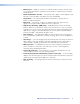
Maintenance and Modifications This section describes: • Opening and Closing the Switcher • Installing a Firmware Upgrade • Installing a DVI Output Card Opening and Closing the Switcher NOTE: Extron recommends that you send the unit in to Extron for service and updates. To replace the firmware or install the optional DVI output card, you need to open the ISM’s case. Open and close the switcher as follows: 1. Disconnect the AC power cord from the ISM to remove power from the unit.
5 3 Lift cover straight up. Remove (16) screws. 4 Remove top two front panel screws. Disconnect from/ connect to 6 J8 and J13. J13 J8 B 8 H/HV 7 6 TS 5 INPU 4 3 G 8 V H/H 7 V H/H Hz V H/H V H/H V H/H B /60 50 X. 0 MA - 24 A 1.2 V H/H B B B 100 V H/H B B G G B B G G V G G G R R R H/HV V R R R 2 1 R R 6 5 V H/H 4 3 Extron ISM 482 2 1 Switcher Figure 49. Removing the ISM Cover 4. Remove the top two front panel screws. 5.
10. Replace the top cover on the ISM. 11. Fasten the top cover with the screws that were removed in step 3 and step 4. 12. Rack mount the switcher if desired and reconnect all cables. Installing a Firmware Upgrade In some cases the ISM firmware may require replacement with an updated version. There are nine user-replaceable firmware chips (see figure 50): U1, U2, and U6 on the front panel circuit board and U98, U99, U100, U101, U102, and U103 on the main circuit board.
4. Align the slots of each new firmware chip with the angled corners of the socket in the same orientation as the old chip. Gently, but firmly, press the chip into place in the socket. 5. Close the switcher (see “Opening and Closing the Switcher,” starting with step 9 on page 65). Installing a DVI Output Card You can install an optional digital visual interface (DVI) output card in the ISS. With the card installed, a additional DVI video output 1 on a standard DVI connector.
4. Position the DVI card above connector J14 with the DVI connector facing toward the rear of the switcher. Ensure that the pins on the DVI card properly align with the J14 connector to prevent bending the pins. 5. Carefully mate the 45-pin connector on the DVI output board with connector J14 on the main circuit board (see figure 52). DVI Connector on DVI Output Card DVI Output Card DVI Output Card Mated to the Main Board via Connector J14 Figure 52. Output DVI Board Installation 6.
Ethernet Connection This section describes: • Cabling • Determining Default Addresses • Connecting as a Telnet Client The rear panel Ethernet connector (see figure 53) on the ISM switcher can be connected to an Ethernet LAN or WAN. This connection makes SIS control of the switcher possible using a computer connected to the same LAN.
Determining Default Addresses To access the ISM switcher via the Ethernet port, you need the Extron ISM IP address. If the address has been changed to an address comprised of words and characters, the actual numeric IP address can be determined using the Ping utility. If the address has not been changed, the factory-specified default is 192.168.254.254. Ping can also be used to test the Ethernet link to the ISM.
Connecting as a Telnet Client The Microsoft Telnet utility is available from the DOS prompt. Telnet allows you to input SIS commands to the ISM from the PC via Ethernet. Access the DOS prompt and start Telnet as follows: 1. Click Start > Run. 2. At the Open prompt, type command. 3. Click the OK button. 4. At the DOS prompt, type telnet and press to figure 55. Enter . The computer returns a display similar Microsoft (R) windows 2000 (TM) Version 5.
Escape character and Esc key When Telnet is first started, the utility advises that the Escape character is ‘Ctrl+]’. Many SIS commands include the keyboard Esc key. Consequently, some confusion may exist between the Escape character and the Escape key. The Telnet Escape character is a key combination, the Ctrl key and the ] key pressed simultaneously, that returns you to the Telnet prompt while leaving the connection to the ISM intact. The Escape key is the Esc key on the computer keyboard.
Reference Information This section includes: • Part Numbers • Button Labels Part Numbers Included Parts These items are included in each order for an ISM 482: Included Parts Part Number ISM 482 60-425-01 Rubber feet (self-adhesive) (4) IEC power cord Tweeker (small screwdriver) ISM 482 Setup Guide Extron Software Products DVD (ISS/ISM Control Program and Button‑Label Generator) Optional Accessories Part Part Number DVI output card 70-244-01 Captive screw audio connector (5 pole, no tail, pkg of
Cables and Connectors When using signals with a scanning frequency of 15-125 kHz and running distances of 100 feet or more, use high resolution BNC cables to achieve maximum performance.
ISM 482 Integrated Scaling Matrix Switcher • Reference Information 75
Extron Warranty Extron Electronics warrants this product against defects in materials and workmanship for a period of three years from the date of purchase.