ISS 408 & ISS 108 Integration Seamless Switchers 68-575-01 Rev.
Precautions Safety Instructions • English This symbol is intended to alert the user of important operating and maintenance (servicing) instructions in the literature provided with the equipment. This symbol is intended to alert the user of the presence of uninsulated dangerous voltage within the product's enclosure that may present a risk of electric shock. Warning Power sources • This equipment should be operated only from the power source indicated on the product.
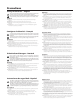
Quick Start — Integration Seamless Switcher Installation Step 1 Turn off power to the ISS 108 or ISS 408 and the input and output devices, and remove the power cords from them. Step 2 If desired, install an optional DVI output card into the switcher. See chapter 7, Maintenance and Modifications. Step 3 Install four rubber feet on the bottom of the ISS or mount the ISS in a rack. AD JU Step 5 Tip Sleeve Cable the switcher for stereo audio input. Each input has a 3.
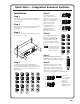
Quick Start — Integration Seamless Switcher, cont’d Step 9 If desired, connect a control system or computer to the Remote RS-232 port. Pin 1 2 3 4 5 6 7 8 9 RS-232 — TX RX — Gnd — — — — 5 Function Not used Transmit data Receive data Not used Signal ground Not used Not used Not used Not used 2. Press an input button (to select the input to configure). 3. Rotate the Adjust video type. knob to select the input 1 4. Rotate the Adjust knob to select the input audio gain or attenuation level.
Table of Contents Chapter 1 • Introduction ....................................................................................................... 1-1 About this Manual ............................................................................................................. 1-2 About the Switcher ............................................................................................................ 1-2 Features ........................................................................................
Table of Contents, cont’d Preview Switch Mode submenu ........................................................................ 3-14 PAL Fil Mode submenu ...................................................................................... 3-15 Reset submenu .................................................................................................. 3-15 User Presets menu ......................................................................................................
Using the Command/Response Table ........................................................................ 4-8 Command/response table for SIS commands .................................................................. 4-9 Command/response table for IP SIS commands ............................................................ 4-15 Command/response table for special function SIS commands ..................................... 4-16 Command/response table for advanced instruction Set commands .....................
Table of Contents, cont’d Chapter 7 • Maintenance and Modifications .......................................................... 7-1 Opening and Closing the Switcher ............................................................................ 7-2 Firmware Upgrade Installation .................................................................................... 7-3 DVI Output Card Installation ........................................................................................
Integration Seamless Switcher 1 Chapter One Introduction About this Manual About the Switcher Features
Introduction, cont’d Introduction About this Manual This manual contains installation, configuration, and operating information for the Extron ISS 108 and ISS 408 Integration Seamless Switchers. The ISS 108 and ISS 408 are similar in function and operation; the differences exist in scaling capabilities. In this manual, the terms “switcher” and “ISS” are used interchangeably to refer to either model, except where differences exist, in which case the specific model is noted.
Preview Monitor Program Monitor Projector Extron ISS 408 M GRA PRO EW TS EVI TPU PR OU M RA R OG PR DVI OUT VIEW PRE R G 32 RS-2 G B B 8 V H/H ET ERN ETH 7 R 6 V H/H LINK ACT V R UTS 5 INP V R G 4 R G 3 R G B 2 R G R G R V H/H B G V H/H B G B G RS-232 B 1 V H/H B V H/H V H/H B 8 V H/H B 7 V H/H Hz 6 5 V H/H 50/60 240 MAX. 100- 1.
Introduction, cont’d Features Inputs — Video inputs — The ISS switches among eight fully-configurable RGB, HDTV component video (ISS 408), component video, S-video, and composite video inputs on five BNC connectors per input. Audio inputs — The ISS switches among eight balanced or unbalanced stereo or mono audio inputs on 5-pole captive screw connectors. Outputs — Standard video outputs — The ISS outputs individually scaled video signals as RGBHV or RGBS.
Audio cross-fading — A transition technique that is applied during the switches that lowers the audio level of the switched out source while simultaneously raising the audio level of the activated source. Ethernet port — Supports connection to an Ethernet LAN so that the switcher can be accessed and operated from a computer running a standard Internet browser anywhere in the world. Quad-standard video decoder — The switcher uses a digital, four-line adaptive comb filter that can decode NTSC 3.58, NTSC 4.
Introduction, cont’d 1-6 Integration Seamless Switcher • Introduction
Integration Seamless Switcher 2 Chapter Two Installation Mounting the Switcher Cabling and Rear Panel Views Configuration
Installation, cont’d Installation Mounting the Switcher Four uninstalled rubber feet are included with the switcher. If you are going to rack mount the switcher, mount it before you cable it (see Rack mounting, below), and do not install the rubber feet. If you are not rack mounting the switcher, see Tabletop placement below. Tabletop placement For tabletop placement, install the self-adhesive rubber feet/pads (provided) onto the four corners of the bottom of the switcher.
Cabling and Rear Panel Views All connectors are on the rear panel (figure 2-2). 2 1 2 3 4 INPUTS 4 5 6 OUTPUTS PROGRAM PREVIEW 8 7 5 PROGRAM R/R-Y R/R-Y R/R-Y R/R-Y R/R-Y R/R-Y R/R-Y R/R-Y R R G/Y VID G/Y VID G/Y VID G/Y VID G/Y VID G/Y VID G/Y VID G/Y VID G G B/C B-Y B/C B-Y B/C B-Y B/C B-Y B/C B-Y B/C B-Y B/C B-Y B/C B-Y B B H/HV H/HV H/HV H/HV H/HV H/HV H/HV H/HV H/HV H/HV V V V V V PREVIEW DVI OUT 8 RS-232 100- 240 50/60 Hz 1.2A MAX.
Installation, cont’d 3 Input audio connectors — Connect balanced or unbalanced stereo or mono audio to these 3.5 mm, 5-pole captive screw connectors. Connectors are included with the seamless switcher, but you must supply the audio cable. Figure 2-4 shows how to wire a connector for the appropriate input type and impedance level. High impedance is generally over 800 ohms.
Standard output connections The two Program Video outputs, consisting of five BNC connectors and a 15-pin HD connector, output the identical video signal and the same sync format. The two Preview Video outputs are also identical to each other. The Program connectors ( 4 ) output the video image for the program monitor or projector. The Preview connectors ( 5 ) output the video image for the local monitor.
Installation, cont’d Optional output connection 8 DVI output connector (optional) — If the optional DVI output card is installed, connect a DVI/DFP-compatible video display to this DVI connector. This connector outputs the program image only. For a DFP-compatible display, connect the display through a DVI-to-DFP adapter, part #26-497-01 (DVI [male] to DFP [female] adapter) or 26-498-01 (DVI [female] to DFP [male] adapter).
Wiring the network cable The cable can be terminated as either a patch cable or a crossover cable (figure 2-8) and must be properly terminated for your application: • Patch (straight) cable — Connection of the ISS to an Ethernet hub, router, or switcher that also hosts a controlling computer. • Crossover cable — Direct connection between the ISS and a controlling computer.
Installation, cont’d RS-232 connection 10 Remote port — Connect a host device, such as a computer or touch panel control, to the Integration Seamless Switcher via this 9-pin D connector for serial RS-232 control (figure 2-9).
Integration Seamless Switcher 3 Chapter Three Operation Front Panel Controls and Indicators Front Panel Operations Optimizing the Video Optimizing the Audio Troubleshooting
Operation, cont’d Operation Front Panel Controls and Indicators All of the switcher’s controls and indicators are on the front panel (figure 3-1). A label window above the input buttons can be labeled with text and/or graphics. The 20 x 4 LCD display indicates the switcher status, menu selections, the data rate, and the status of additional system features.
4 Cut button — Pressing the Cut button causes the ISS to immediately switch the input selected as the preview output to the program output, with no switching effects added. If black screen and/or mute audio is selected for the program output, it is deselected when a cut is selected. Dissolve button — Pressing the Dissolve button causes the ISS to switch the input selected as the preview output to the program output using the dissolve effect.
Operation, cont’d Center control button — The Center button selects the display centering adjustment. The adjustment range depends on the output resolution selected. See Picture adjustments in this chapter. Filter control (Detail) button — The Detail button selects the display image detail (sharpness) adjustment. There are separate horizontal and vertical filters for RGB and component video. There is a single filter for S-video and composite video. The sharpness adjustment compensates for long cable runs.
On figure 3-4 and all other flowcharts in this chapter, solid lines indicate screen changes initiated by the operator. Dashed lines indicate screen changes that are the result of a timeout function. Default Display Cycle Power on Extron Electronics ISS 408 Integration Seamless Switcher 2 sec. Extron Electronics ISS 408 60-423-01 Version x . xx Program #1 RGB 0.00 kHz 0.00Hz Preview #3 S-Video 0.00 kHz 0.00Hz 2 sec. Output Rate 1280 x 1024 @ 60 2 sec. 2 sec.
Operation, cont’d 3. Press and release either the Cut or Dissolve button. Cut button — The ISS immediately switches the input selected as the preview output to the program output, with no switching effects added (figure 3-7). CUT Press and release the Cut button. The Input 3 video (upper) LED and Input 3 audio (lower) LED immediately light steadily to indicate that the video and audio inputs are selected, the video is scaled, and output as the program output.
Recalling a user preset There are three user presets per input. The presets save color, tint, contrast, brightness, detail, sizing, and centering settings. See User Presets menu later in this chapter to save and erase presets. Cycle through and recall these memories by repeatedly pressing the appropriate input button. The LCD panel identifies the recalled preset (figure 3-9).
Operation, cont’d Menu system overview Figure 3-10 shows a flowchart of the main menus in the menu system. Power on Extron Electronics ISS 408 Integration Seamless Switcher 2 sec. Extron Electronics ISS 408 60-423-01 Version x . xx 2 sec. Default Cycle Menu 10 sec. 10 sec. Video & Audio Configuration Menu Output Configuration 10 sec. Menu Advanced Configuration 10 sec. 10 sec.
From any menu or submenu, after 10 seconds of inactivity, the ISS saves all adjustment settings and times out to the default LCD display cycle. Video & Audio Configuration menu Figure 3-11 is a flowchart that shows an overview of the Video & Audio Configuration menu and the available settings. Default Cycle Menu 10 sec. Video & Audio Configuration 10 sec. Next Video/Audio Config Next Menu Input #1 Composite Audio #3 Level -12db Menu NOTE The audio is broken away in this example.
Operation, cont’d Output Configuration menu Figure 3-12 is a flowchart that shows an overview of the Output Configuration menu, the submenus, and the available settings. Default Cycle Menu 10 sec. Video & Audio Configuration Menu 10 sec. Output Configuration 10 sec.
50 Hz 640 x 480 108, 408 108, 408 108, 408 108, 408 800 x 600 108, 408 108, 408 108, 408 108, 408 832 x 624 108, 408 108, 408 108, 408 848 x 480 108, 408 108, 408 852 x 480 108, 408 108, 408 108, 408 108, 408 108, 408 108, 408 1024 x 768* 108, 408 1280 x 768* 1280 x 1024* 56 Hz 60 Hz 408 only 408 only 75 Hz 85 Hz Lock at 50/60 Hz✝ Resolution 408 only 408 only 1360 x 765 408 only 408 only 1365 x 1024 408 only 408 only 408 only 408 only 1400 x 1050 408 only 576p HDTV
Operation, cont’d Advanced Configuration menu Figure 3-13 is a flowchart that shows an overview of the Advanced Configuration menu, the submenus, and the available settings. Default Cycle Menu 10 sec. Video & Audio Configuration Change this value with either Adjust knob. 10 sec. Menu Dissolve Speed 1.0 Second Output Configuration Next Time of the dissolve (Dissolve button) 0.1 – 5.0 seconds Menu Next Select top blanking with the Adjust knob. Select bottom blanking with the Adjust knob.
Dissolve Speed submenu The Dissolve Speed submenu displays and allows you to set the duration of the dissolve effect when switching the preview output to the program output. Use either the Adjust knob or the Adjust knob to select the dissolve speed from 0.1 seconds to 5.0 seconds in 0.1 second steps. The default is 1.0 seconds. Test Pattern submenu The Test Pattern submenu lets you select from among several test patterns and assigns the selected pattern to an output.
Operation, cont’d Auto Imaging and Auto Memories submenu The Auto Imaging and Auto Memories menu provides a means to turn the auto imaging and auto presets features on or off for all input selections. If auto imaging is set to on, the ISS automatically sizes and centers the selected input to fill the screen when a new frequency is input.
CUT ISS CUT DISSOLVE DISSOLVE Press Cut or Dissolve Press Cut or Dissolve Scaler A Input 1 (program output) Scaler A Program Monitor (input 2) Input 1 (program output) Program Monitor (input 2) Scaler B Input 2 (preview output) ISS RS-232 Report Scaler B Preview Monitor (input 2) Input 2 (preview output) NO RS-232 Report Stay Mode Swap Mode Scaler A Changes Inputs Neither Scaler Changes Inputs Preview Monitor (input 1) Figure 3-14 — Stay mode and swap mode Use either the Adjust knob o
Operation, cont’d User Presets menu Figure 3-15 is a flowchart that shows an overview of the User Presets menu, the Save Preview Preset and Erase Preview Preset submenus, and the available settings. Default Cycle Menu 10 sec. Video & Audio Configuration Menu Output Configuration Menu Advanced Configuration Menu User Presets 10 sec. Next Save Preview Preset 10 sec.
User presets are recalled using the Input buttons. See Input buttons earlier in this chapter for instructions on recalling a user preset. Erase Preview Presets submenu Rotate either the Adjust or the Adjust knob while in the Erase Preview Presets submenu to highlight (< >) one of three user presets to erase or highlight N/A for no preset. Press the Next button to erase the user preset. Highlight N/A and press the Next button to exit without erasing the presets.
Operation, cont’d Picture adjustments The picture adjustments allow you to fine tune the image quality of the selected input. When you press one of the Picture Adjustments buttons (Color/Tint, Brightness/Contrast, Size, Center, or Filter) once, the corresponding image adjustment menu for the preview image appears on the LCD screen. Press the button again, and the corresponding image adjustment menu for the program image appears.
2. Press the appropriate picture adjustment button: color and tint (Col/Tnt), brightness and contrast (Brt/Cont), sizing (Size), centering (Center), or filter. The LCD display shows the name of the adjustment and the current setting value. 3. Rotate the Adjust knob or the Adjust knob to vary the settings within the following adjustment ranges: The Adjust knobs have no mechanical limits to their rotation. 4. • Color/Tint: Color adjusts within a range from 0 to 127.
Operation, cont’d IP information To set up the ISS for operation via its Ethernet port, you need to know and be able to change the IP address. One way to do this is via the IP address and hardware address screen. To access the IP address and hardware address screen, press and hold the Color/Tint and Detail buttons while you apply power to the ISS (figure 3-19). When the ISS is finished intializing, it displays both addresses.
1. If you are using a digital display, such as an LCD or DLP projector, use the alternating pixels test pattern as a reference to adjust the phase and dot clock on the display devices. Proceed to step 3. 2. If you are using a CRT display, use the cross hatch test pattern as a reference to converge the display. 3. Set the ISS to output either the crop test pattern for 4:3 video or the appropriate aspect ratio test pattern.
Operation, cont’d Optimizing the Audio Each individual input audio level can be adjusted within a range of -24 dB to +9 dB, so there are no noticeable volume differences between sources and for the best headroom and signal-to-noise ratio. Adjust the audio gain and attenuation as follows: 1. Connect audio sources to all desired inputs and connect the audio outputs to output devices such as audio players. See Input connections and Standard output connections, in chapter 2, Installation.
Specific problems The table below shows some common operating problems and their solutions. Problem No image appears. Cause The input signal is incompatible. Solution Connect an input device that is compatible with the ISS. The input is improperly Use the Video & Audio configured. Configuration submenu to select the correct input format. Freeze mode was entered via an SIS command when the image was black. Deactivate freeze mode via an SIS command. The scaled output rate is too high for the display.
Operation, cont’d 3-24 Integration Seamless Switcher • Operation
Integration Seamless Switcher 4 Chapter Four Programmer’s Guide RS-232 Link Ethernet Link Symbols Switcher-Initiated Messages Host-to-Switcher Instructions Switcher Error Responses Using the Command/Response Table
Programmer’s Guide RS-232 Link The switcher’s rear panel Remote 9-pin D female connector (figure 4-1) can be connected to the RS-232 serial port output of a host device such as a computer running the HyperTerminal utility or a control system. This connection makes software control of the switcher possible.
Ethernet connection The cable can be terminated as either a patch cable or a crossover cable (figure 4-2) and must be properly terminated for your application: • Patch (straight) cable — Connection of the ISS to an Ethernet hub, router, or switcher that also hosts a controlling computer. • Crossover cable — Direct connection between the ISS and a computer. Default address To access the switcher via the Ethernet port, you will need the switcher’s IP address.
Programmer’s Guide, cont’d Switcher-Initiated Messages When a local event such as power-up or a front panel operation occurs, the switcher responds by sending a message to the host. The switcher-initiated messages are listed in the following pages. The messages are underlined. The switcher does not expect a response from the host, but the host program may request a new status. Power-up (c) Copyright 2002, Extron Electronics, ISS 408 Vx.
Cutting or dissolving in swap mode The switcher issues the following reports when you swap the preview and program outputs in stay mode: Tke X4 (SIS operation response only) The switcher has received the SIS “Take” (%) command. Bsy1 The switcher is busy and will not respond to any SIS commands. Out1•In X1 •All (or RGB or Aud) The input to the program output has changed (to the input that had been switched to preview output).
Programmer’s Guide, cont’d X2 Hsz X13 A front panel horizontal size adjustment has occurred. and X13 is the size variable. X2 is the output number Vsz X13 A front panel vertical size adjustment has occurred. X13 is the size variable. X2 X2 X2 is the output number and Hph X14 A front panel horizontal centering adjustment has occurred. number and X14 is the centering variable. X2 X2 is the output number X2 is the output number Blt X15 A front panel top line blanking adjustment has occurred.
Dur X20 A front panel dissolve speed adjustment has occurred. Dissolve speed affects the duration of the dissolve function when switching the preview output to the program output. X20 is the delay value, in 0.01 second steps. X20 can be as much as 50 = 5.0 seconds. Test pattern Tst X21 * X22 A test pattern has been turned on or off for one or both outputs from the front panel. X21 is the on/off status for either or both outputs and X22 is the test pattern selected.
Programmer’s Guide, cont’d Automated adjustments Img X3 The Auto Image feature has been turned on or off from the front panel for all input selections. X3 is the on/off status. Aut X3 The auto presets feature has been turned on or off from the front panel for all input selections. X3 is the on/off status. Enh X3 The enhanced mode feature has been turned on or off from the front panel for S-video or composite video tied to both outputs. X3 is the on/off status for the two outputs.
Command/response table for SIS commands Command ASCII Command Response (host to switcher) (switcher to host) Additional description Input selection You can select an input for either output (preview or program) using SIS commands. Select video and audio Example: X2 * X1 ! 1*2! Out X2 •In X1 •All Out1•In2•All Select video only X2 * X1 & Out X2 •In X1 •RGB 2*5& Out2•In5•RGB X2 * X1 $ Out X2 •In X1 •Aud Example: Select audio only Select input X1 to X2 output.
Programmer’s Guide, cont’d Command/response table for SIS commands (cont’d) Command ASCII Command Response (host to switcher) (switcher to host) X6 * X7 = 5*4= = Rte X6 * X7 Rte05*4 Rte X6 * X7 Additional description Scaler output video type Set output resolution and rate Example: View resolution and rate Command character is “equals”. Set output to 1024x768 at 85Hz. Color Color adjustments are available only for interlaced component video (YUVi), S-video, and composite video inputs.
Command/response table for SIS commands (cont’d) Command ASCII Command Response (host to switcher) (switcher to host) X2 * X14 H X2 Hph X14 X2 +H X2 Hph X14 X2 -H X2 Hph X14 Additional description Horizontal shift Set a specific horizontal position Increment right Decrement left View the horizontal position X2 H X14 Specify the horizontal position. Shift the picture right. Shift the picture left. Show the horizontal position.
Programmer’s Guide, cont’d Command/response table for SIS commands (cont’d) Command ASCII Command Response (host to switcher) (switcher to host) Additional description Vertical detail filter (RGB and component video inputs) The vertical detail filter is available only for RGB and component video inputs. The X2 value specified is the output to which the filtered input is switched. The command (d) is case sensitive.
Command/response table for SIS commands (cont’d) Command ASCII Command Response (host to switcher) (switcher to host) Additional description Set audio gain and attenuation Set gain Example: X1 * X24 G 4*3G X1 Aud X23 4Aud+•3 Set gain for input X1 to X24 dB. Set gain for input 4 to 3 dB. The command (G) is case sensitive. Set attenuation X1 * X25 g X1 Aud X23 Set attenuation for input X23 dB. Increase input X1 audio level by +1 dB. Decrease input X1 audio level by -1 dB.
Programmer’s Guide, cont’d Command/response table for SIS commands (cont’d) Command ASCII Command Response (host to switcher) (switcher to host) Additional description Information requests Query firmware version number Q x.xx Show the controller firmware version. Show the ISS’s part #. Request part number N zz-zzz-zz Request general information X2 I (See below) Show the ISS’s status.
Command/response table for IP SIS commands X30 = ISS name (Up to 240 characters) X31 = GMT Time and date (set) MM/DD/YY-HH:MM:SS, where MM = month: 01 (January) through 12 (December) DD = day: 01 through 31 YY = year: 00 through 99 HH = hour: 00 through 24 MM = minutes: 00 through 59 SS = seconds: 00 through 59 X32 = Time and date (read) In the format: Day,•DD•MMM•YYYY•HH:MM:SS GMT, where Day = weekday: Mon through Sun DD = day: 01 through 31 MM = month: Jan through Dec YYYY = year: 2000 through 209
Programmer’s Guide, cont’d Command/response table for special function SIS commands The syntax for setting a special function is Xn * X? # where Xn is the value or variable (such as 35 in the first example below), X? is the function number (such as “set RGB delay” in the first example below), and # is the execute command. To view a function’s setting, use X? # where X? is the function number.
Command/response table for special function SIS commands (cont’d) Command ASCII Command Response (host to switcher) (switcher to host) Additional description Auto Image Set Auto Image X3 *13# Img X3 Example: 1*13# Img01 Execute Auto Image X18 *14# Img X18 00 = off. 01 = on. Set Auto Image on. X18 : Auto Image input tied to output: Prog/Prev Prog/Prev 01 = Yes/No 03 = Yes/Yes 02 = No/Yes Output X2 Auto Image complete. Output X2 Auto Image complete.
Programmer’s Guide, cont’d Command/response table for advanced instruction set commands The advanced instruction set consists of four hexadecimal commands for uploading and downloading all or a portion of the switcher’s memory. These commands are for use by knowledgeable programmers, and result in a dump of data from (upload) or to (download) the switcher. Programmers can use the commands to exactly duplicate the settings among switchers with a minimum of effort.
Integration Seamless Switcher 5 Chapter Five Switcher Software Control Software for Windows Button-Label Generator
Switcher Software Control Software for Windows Two software programs accompany the ISS 108 and ISS 408: • The Extron ISS/ISM Control Program (Extron part #29-054-01), which communicates with the switcher via the rear panel Remote port, provides an easy way for you to control the switcher. • The Extron Button-Label Generator, which allows you to design and print a label strip for the switcher’s front panel input selection button window.
Using the control program Many items found in the ISS/ISM Control Program are also accessible via front panel controls and the LCD menus, see chapter 3, Operation, and under SIS control, see chapter 4, Programmer’s Guide. The ISS/ISM Help Program provides information on settings and on how to use the control program itself. 1. To run the control program, double-click the ISS/ISM Control Pgm icon in the Extron Electronics group or folder. The Comm menu appears on the screen (figure 5-1).
Switcher Software, cont’d 5. The Extron ISS/ISM Control Program window (figure 5-3) appears. Figure 5-3 — Windows Control program window 6. If desired, on the task bar, click Tools > I/O Configuration to configure the video inputs and outputs in the I/O configuration window (figure 5-4). Figure 5-4 — Control program I/O Configuration window 7. If desired, on the task bar, click Tools > Audio Settings to set each input’s audio level or attenuation in the Audio Settings window (figure 5-5).
8. If desired, on the task bar, click Tools > IP Options to set the switcher’s IP parameters in the IP Settings/Options window (figure 5-6). Figure 5-6 — Control program IP Setting/Options window When the control program is connected to the switcher via the RS-232 link, the Administrator and User password fields are not masked. If a password has been inadvertently changed to an unknown value, you can look up and, if desired, change a password in this window without knowing the current password.
Switcher Software, cont’d Figure 5-7 — Extron’s Button-Label Generator window 3. Using normal Windows controls, you can create and print labels that can be cut out and placed in the label windows on the front panel of the ISS. For information about using the program, you can access a help file by clicking on the Help menu on the main screen and choosing Show Help.
Integration Seamless Switcher 6 Chapter Six Ethernet Operation Load the Startup (Control) Page Control Page System Configuration Page File Management Page I/O Configuration Page
Ethernet Operation, cont’d Ethernet Operation The ISS 108 and ISS 408 can each be controlled and operated through its Ethernet port, connected via a LAN or WAN, using a Web browser such as Microsoft’s Internet Explorer. The browser’s display of the switcher’s status or operation has the appearance of Web pages. This chapter describes the factory-installed HTML pages, which are always available and cannot be erased or overwritten.
7. The switcher checks several possibilities, in the following order, and then responds accordingly: a. Does the address include a specific file name, such as 10.13.156.10/file_name.html? If so, the switcher downloads that HTML page. b. Is there a file in the switcher ’s memory that is named “index.html”? If so, the switcher loads “index.html” as the default startup page. c. If neither of the above conditions is true, the switcher loads the factoryinstalled default startup page, “nortxe_index.
Ethernet Operation, cont’d Select and switch an input Select and switch an input as follows: 1. Click the Video/Audio, Video, or Audio button to select both the video and audio planes, the video plane only, or the audio plane only for switching (audio follow or audio breakaway). 2. Select an input for the preview or program monitor by clicking the desired input button in either the Preview or Program row.
Blackout the screen and mute the audio You can mute the video (blackout the screen) and/or audio to the program or preview output from the Control page as follows: 1. Click the Video/Audio, Video, or Audio button to select both the video and audio planes, the video plane only, or the audio plane only for muting. 2. Click the Program or Preview Black/Mute button. The Black/Mute button turns blue to indicate a video and audio mute or video only mute or yellow to indicate audio mute.
Ethernet Operation, cont’d Front panel security lockout (executive mode) You can toggle the front panel security lockout on and off by clicking the Executive Mode On or Off checkbox. The security lockout limits the operation of the Integration Seamless Switcher from the front panel. When the switcher is locked, all of the front panel functions are disabled except for input selection.
The administration fields on the System Configuration page are for entering and verifying administrator and user passwords. Passwords are case sensitive and are limited to 12 upper case and lower case alphanumeric characters. Each password must be entered twice; once in the password field and then repeated in the re-enter password field. Characters in these fields are masked by asterisks (*****).
Ethernet Operation, cont’d File Management Page To delete files such as HTML pages from the ISS or to upload your own files to the ISS, click the File Management tab. The switcher downloads the file management HTML page (figure 6-6). Figure 6-6 — File Management page To delete a file, check the associated delete check box and click the Delete Files button. Upload your own files as follows: 6-8 1. Click the Browse button. 2. Browse through your system and select the desired file(s). 3.
I/O Configuration Page You can set up the input configurations and the output format on the I/O Configuration page (figure 6-7). Access the I/O Configuration page by clicking the I/O Configuration tab. Figure 6-7 — Setup page Input configuration You can specify the format of each input. The available formats are RGB, RGBcvS (identified as RGBcS in the drop box), YUVi, YUVp, Betacam 50, Betacam 60, HDTV, S-video, and composite video. Specify the input format as follows: 1.
Ethernet Operation, cont’d Output resolution, rate, sync format, and polarity The ISS 408 scales the input up or down to any 1 of 40 output resolutions and rates. The ISS 108 scales the inputs to 1 of 20 resolutions and rates. Either switcher outputs the scaled video, as RGBHV or RGBS, with user-selectable polarity, via either the program or preview connectors. The table below shows the resolutions and rates available on the ISS 408 and ISS 108.
Output resolution Select the output resolution as follows: 1. Click the Resolution field. A drop down scroll box appears (figure 6-9). Figure 6-9 — Resolution scroll box 2. Click and drag on either the slider or click the scroll up ( ) or scroll down ( ) buttons until the desired rate is visible. 3. Click the desired output. 4. Click the Submit button. Output rate Select the output rate as follows: 1. Click the Rate field. A drop down box appears (figure 6-10). Figure 6-10 — Rate drop box 2.
Ethernet Operation, cont’d Output format Select between separate horizontal (H) and vertical (V) sync or composite (S) sync as follows: 1. Click the Type field. A drop down box appears (figure 6-11). Figure 6-11 — Type drop box 2. Click the desired sync type. 3. Click the Submit button. Output polarity Select the output polarity as follows: 1. Click the Polarity field. A drop down box appears (figure 6-12). Figure 6-12 — Polarity drop box 6-12 2. Click the desired polarity. 3.
Integration Seamless Switcher 7 Chapter Seven Maintenance and Modifications Opening and Closing the Switcher Firmware Upgrade Installation DVI Output Card Installation
Maintenance and Modifications Opening and Closing the Switcher To replace the firmware or install the optional DVI output card, you will need to open the ISS’s case. Extron recommends that you send the unit in to Extron for service and updates. Open and close the switcher as follows: 1. Disconnect the AC power cord from the ISS to remove power from the unit. To prevent electric shock, always unplug the ISS from the AC power source before opening the enclosure. 2.
4. Remove the top two front panel screws. 5. Lift the top cover straight up approximately five inches until you can access the fan power cords. CAUTION Do not touch any switches or other electronic components inside the ISS. Doing so could damage the switcher. Electrostatic discharge (ESD) can damage IC chips even though you cannot feel it. You must be electrically grounded before proceeding with firmware replacement. A grounding wrist strap is recommended. 6.
Maintenance and Modifications 5. Close the switcher. See Opening and Closing the Switcher, starting on step 9 on page 7-3. DVI Output Card Installation You can install an optional digital visual interface (DVI) output card in the ISS. With the card installed, the program output outputs DVI video on a standard DVI connector as well as the standard RGB video on BNC connector and 15-pin HD connectors. We recommend that you send the unit to Extron for service and updates.
3. If the rear panel DVI connector opening is still covered, remove the two screws that secure the cover to the back panel and remove the cover. 4. Position the DVI card above connector J14 with the DVI connector facing toward the rear of the switcher. Ensure that the pins on the DVI card properly align with the J14 connector to prevent bending the pins. 5. Carefully mate the 45-pin connector on the DVI output board with connector J14 on the main circuit board (figure 7-3).
Maintenance and Modifications 7-6 Integration Seamless Switcher • Maintenance and Modifications
Integration Seamless Switcher A Appendix A Ethernet Connection Ethernet Link
Ethernet Connection, cont’d Ethernet Link The rear panel Ethernet connector (figure A-1) on the ISS switcher can be connected to an Ethernet LAN or WAN. This connection makes SIS control of the switcher possible using a computer connected to the same LAN.
Default address To access the ISS switcher via the Ethernet port, you will need the Extron ISS IP address. If the address has been changed to an address comprised of words and characters, the actual numeric IP address can be determined using the Ping utility. If the address has not been changed, the factory-specified default is 192.168.254.254. Ping can also be used to test the Ethernet link to the ISS. Ping to determine the switcher’s IP address The Microsoft Ping utility is available at the DOS prompt.
Ethernet Connection, cont’d Connect as a Telnet client The Microsoft Telnet utility is available from the DOS prompt. Telnet allows you to input SIS commands to the ISS from the PC via the Ethernet link and the LAN. Access the DOS prompt and start Telnet as follows: 1. Click on Start > Run. 2. At the Open prompt, type command. 3. Click on the OK button. 4. At the DOS prompt, type telnet and press [Enter]. The computer returns a display similar to figure A-3. Microsoft (R) windows 2000 (TM) Version 5.
Once you are logged in, the ISS returns either Login Administrator or Login User. No further prompts are displayed until you break or disconnect the connection to the ISS. Escape character and Esc key When Telnet is first started, the utility advises that the Escape character is ‘Ctrl+]’. Many SIS commands include the keyboard Esc key. Consequently, some confusion may exist between the Escape character and the Escape key.
Ethernet Connection, cont’d A-6 Integration Seamless Switcher • Ethernet Connection
Integration Seamless Switcher B Appendix B Reference Information Specifications Part Numbers Button Labels
Reference Information Specifications Video input Number/signal type ................... 8 RGBHV, RGBS, RGsB, RGBcvS, component video, S-video, composite video Connectors ................................... 8 x 5 female BNC Nominal level ............................... 1V p-p for Y of component video and S-video, and for composite video 0.7 V p-p for RGB 0.3V p-p for R-Y and B-Y of component video, and for C of S-video Minimum/maximum levels ....... 0 V to 1.0 V p-p with no offset Impedance .................
Audio Gain ................................................ Frequency response .................... THD + Noise ................................. S/N ............................................... Crosstalk ....................................... Stereo channel separation .......... CMRR ............................................ Unbalanced output: 0 dB; balanced output: +6 dB 20 Hz to 20 kHz, ±0.05 dB 0.
Reference Information, cont’d Listings .......................................... Compliances ................................. MTBF ............................................. Warranty ....................................... UL, CUL CE, FCC Class B 30,000 hours 3 years parts and labor Specifications are subject to change without notice.
BNC-4 Mini HR Cable BNC-4 Mini HR bulk, 500’ 22-032-02 BNC-4 Mini HR bulk, 1000’ 22-032-03 BNC-5 Mini HR Cable BNC-5 Mini HR bulk, 500’ 22-020-02 BNC-5 Mini HR bulk, 1000’ 22-020-03 Plenum BNC-5 Mini HR Cable Plenum BNC-5 Mini HR bulk, 500’ 22-103-02 Plenum BNC-5 Mini HR bulk, 1000’ 22-103-03 Assorted connectors BNC connectors BNC Mini HR crimp connectors, qty. 50 100-074-51 SHR male crimp connectors, qty. 50 100-075-51 BNC bulkhead connectors, qty.
Reference Information, cont’d B-6 Integration Seamless Switcher • Reference Information
Integration Seamless Switcher • Reference Information B-7
Reference Information, cont’d B-8 Integration Seamless Switcher • Reference Information
FCC Class B Notice This equipment has been tested and found to comply with the limits for a Class B digital device, pursuant to part 15 of the FCC Rules. These limits are designed to provide reasonable protection against harmful interference in a residential installation. This equipment generates, uses and can radiate radio frequency energy and, if not installed and used in accordance with the instructions, may cause harmful interference to radio communications.
www.extron.com Extron Electronics, USA Extron Electronics, Europe Extron Electronics, Asia Extron Electronics, Japan 1230 South Lewis Street Anaheim, CA 92805 USA 714.491.1500 Fax 714.491.1517 Beeldschermweg 6C 3821 AH Amersfoort The Netherlands +31.33.453.4040 Fax +31.33.453.4050 135 Joo Seng Road, #04-01 PM Industrial Building Singapore 368363 +65.6383.4400 Fax +65.6383.4664 Kyodo Building 16 Ichibancho Chiyoda-ku, Tokyo 102-0082 Japan +81.3.3511.7655 Fax +81.3.3511.