CrossPoint 450 Plus Series MAV Plus series Large Scale Matrix Switchers 68-521-03 Rev.
Precautions Safety Instructions • English Warning This symbol is intended to alert the user of important operating and maintenance (servicing) instructions in the literature provided with the equipment. Power sources • This equipment should be operated only from the power source indicated on the product. This equipment is intended to be used with a main power system with a grounded (neutral) conductor. The third (grounding) pin is a safety feature, do not attempt to bypass or disable it.
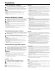
Quick Start — CrossPoint 450 Plus and MAV Plus Switchers Installation of multiple BME system Rack mount the switcher BMEs. Step 1 — Numbering the BMEs 64 Each BME must be set to a unique address of 0 through 5. 63 62 BME address switch — To set the BME address, press the + and - buttons on the BME Address switch on the rear panel of the switcher BMEs, as shown at right. N Addresses 6 through 9 are invalid. The addresses used in the system must be sequential with no skipped numbers.
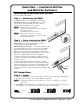
Quick Start — CrossPoint 450 Plus and MAV Plus Switchers, cont’d Step 4 — Outputs a. Video and sync BMEs — Connect a single plane of video or sync, as appropriate to the BME, to the BNC connectors on the video and sync BMEs for each output. N b. Each BME supports one video or sync plane only. See figure 1-1 in chapter 1 for an example configuration. Audio BME — Connect balanced or unbalanced stereo audio or mono audio devices, as appropriate to the BME type, to the captive screw connectors.
Table of Contents Chapter One • Introduction ...................................................................................................... 1-1 About this Manual..................................................................................................................... 1-2 About the Matrix Switchers ................................................................................................ 1-2 Definitions ...............................................................................
Table of Contents, cont’d Muting and unmuting video and/or audio outputs ..........................................................3-29 Example 9: Muting and unmuting an output..................................................................3-30 Viewing and adjusting the input audio level (systems with audio BMEs)......................3-32 Example 10: Viewing and adjusting an input audio level ..............................................
Chapter Five • Matrix Software .............................................................................................5-1 Matrix Switchers Control Program ................................................................................. 5-2 Installing the software ............................................................................................................. 5-2 Software operation via Ethernet ............................................................................................
Table of Contents, cont’d Chapter 6 • HTML Operation ..................................................................................................... 6-1 Download the Startup Page ................................................................................................ 6-2 System Status Page .................................................................................................................. 6-3 DSVP page (systems with a sync BME only)................................................
Appendix A • Ethernet Connection .................................................................................... A-1 Ethernet Link ............................................................................................................................... A-2 Ethernet connection ................................................................................................................ A-2 Default address ...........................................................................................
PRELIMINARY Table of Contents, cont’d All trademarks mentioned in this manual are the properties of their respective owners.
1 Chapter One Introduction About this Manual About the Matrix Switchers Definitions Features PRELIMINARY CrossPoint 450 Plus and MAV Plus Switchers
Installation About this Manual This manual contains installation, configuration, and operating information for the Extron family of full-function, very large CrossPoint 450 Plus ultra-wideband and MAV Plus 3248 through 6464 video and audio matrix switchers. About the Matrix Switchers Matrix switchers distribute any input to any combination of outputs. The matrix switchers can route multiple input/output configurations simultaneously.
Some BMEs are equipped with an integrated QuickSwitch-Front Panel Controller (QS-FPC™): • The CrossPoint 450 Plus Video BME is available with or without a QS-FPC. • The MAV Plus video BME is always equipped with a QS-FPC. • The CrossPoint 450 Plus Sync BME is not available with a QS-FPC. • The MAV Plus audio BME (stereo or mono) is not available with a QS-FPC. • BMEs without a QS-FPC are equipped with a blank front panel.
Introduction, cont’d A low resolution video matrix switcher system requires a MAV Plus Video BME for each video plane (three BMEs for component video, two BMEs for S-video, or one BME for composite video). To add audio to the system requires a MAV Plus Stereo or Mono Audio BME. N Multiple QS-FPCs are unnecessary and potentially confusing. To avoid confusion, Extron recommends that you lock the redundant QS-FPCs. See Locking out the front panel (Executive mode) on page 3-40.
Definitions The following terms, which apply to Extron matrix switchers, are used throughout this manual: Tie — An input-to-output connection. Set of ties — An input tied to two or more outputs. (An output can never be tied to more than one input.) Configuration — One or more ties or one or more sets of ties. Current configuration — The configuration that is currently active in the switcher (also called configuration 0).
Introduction, cont’d Audio output volume (systems with audio BMEs) — The audio volume of each output can be displayed and adjusted through a range of full output to completely silent, from the front panel or under RS-232/RS-422 or Ethernet control. Digital Sync Validation Processing (DSVP™) (CrossPoint 450 Plus Sync BMEs) — In critical environments or unmanned, remote locations, it may be vital to know that sources are active and switching.
• Tie any input to any or all outputs • Quick multiple tie — Multiple inputs can be switched to multiple outputs simultaneously. This allows all displays (outputs) to change from source to source at the same time. • Audio follow — Audio can be switched with its corresponding video input via front panel control or under Ethernet or RS-232/RS-422 remote control. • Audio breakaway — Audio can be broken away from its corresponding video signal.
Introduction, cont’d Labeling — Extron’s included button label software lets you create labels to place in the front panel I/O buttons, with names, alphanumeric characters, or color bitmaps for easy and intuitive input and output selection. Alternatively, labels can be made with any Brother™ P-Touch™ or comparable labeler. Global memory presets — 64 global memory presets are a time-saving feature that lets you set up and store input/output configurations in advance.
2 Chapter Two Installation Mounting the Switcher Rear Panel Views Front Panel Configuration Port PRELIMINARY CrossPoint 450 Plus and MAV Plus Switchers
Installation Mounting the Switcher The matrix switcher BMEs are housed in rack-mountable, 6U (sync and video BMEs) or 7U (audio BMEs) high metal enclosures with 19" rack ears. If desired, rack mount the switcher BME as follows: 1. Insert the switcher BME into the rack, aligning the holes in the mounting bracket with those in the rack. 2. Secure the switcher BME to the rack using the supplied bolts. Rear Panel Views All connectors for all switcher BMEs are on the rear panel.
4 8 10 9 6 12 7 5 Figure 2-2 — MAV Plus 6464 Stereo Audio BME Video or sync input and output (video and sync BMEs) N The switchers do not alter the input video or sync signal in any way. The signal output by the BME is in the same format as the input. The switcher can connect to up to as many as 64 video sources, depending on the model. The switcher can output to as many as 64 video devices, depending on the model.
Installation, cont’d Sync termination switches (systems with sync BMEs) c Sync termination switches — The CrossPoint 450 Plus Sync 12345678 matrix switcher BMEs have sync termination switches on 75 the rear panel for inputs 1 through 16. The switches provide a way to condition non-TTL sync levels greater than 5 Vp-p, 510 10 12 14 16 enabling the sync to be properly passed from input to 9 11 13 15 selected output(s). 75 Each switch provides the option of selecting either 510 ohms 510 or 75 ohms.
See figure 2-4 to wire a connector on a mono audio BME. 0.2” (5 mm) max. Do not tin the wires! Tip Ring Sleeves Figure 2-4 — Captive screw connector wiring for mono audio inputs N The length of exposed wires is critical. The ideal length is 0.2” (5 mm). • If the stripped section of wire is longer than 0.2”, the exposed wires may touch, causing a short circuit between them. • If the stripped section of wire is shorter than 0.
Installation, cont’d See figure 2-7 to properly wire an output connector for the mono audio BME. 0.2” (5 mm) max. Do not tin the wires! Tip Ring Sleeves Figure 2-7 — Captive screw connector wiring for mono audio output N The length of exposed wires is critical. The ideal length is 0.2” (5 mm). • If the stripped section of wire is longer than 0.2”, the exposed wires may touch, causing a short circuit between them. • If the stripped section of wire is shorter than 0.
g BME COMM interconnect ports — If the matrix switcher system consists of more than one BME, the BMEs must be connected together in a daisy chain using Extron-supplied RJ-45 cables. Connect the first daisy chain from BME 0’s BME Comm Out connector to the nearest BME’s BME Comm In connector (figure 2-9). In a rack where BMEs are arranged so that their physical location matches the BME address numbering, this would be BME 1. But since not all systems are configured alike, call this module BME n.
Installation, cont’d RS-232/RS-422 1 5 6 9 RS232/RS422 RS-232/RS-422 connector — Connect a host device, such as a computer, touch panel control, or RS-232 capable PDA to the switcher via this 9-pin D connector on BME 0 only for serial RS-232/RS-422 control (figure 2-10).
Cabling and RJ-45 connector wiring It is vital that your Ethernet cables be the correct cables, and that they be properly terminated with the correct pinout. Fast Ethernet links use Category (CAT) 5e or CAT 6, unshielded twisted pair (UTP) or shielded twisted pair (STP) cables, terminated with RJ-45 connectors. Ethernet cables are limited to a length 328' (100 m). N Do not use standard telephone cables. Telephone cables will not support Ethernet or Fast Ethernet. Do not stretch or bend cables.
Installation, cont’d Reset button j Reset button — The Reset button initiates four levels of reset to the matrix switcher. Press and hold the button while the switcher is running or while you power up the switcher for different reset levels. Rx RESET See Performing soft system resets in chapter 3, Operation, for details. • Events (mode 3) reset — Hold Reset for 3 seconds then release and push again to toggle events monitoring on and off.
Extron BBG 6 A Black Burst Color Bar Audio Generator OUT Connect to MAV Plus 6464. Tee-connector Terminate cable or connect to another device.
Installation, cont’d Front Panel Configuration Port m Configuration port — This 2.5 mm mini stereo jack (figure 2-14) serves the same serial communications function as the rear panel Remote port, but it may easier to access. The optional 9-pin D to 2.5 mm stereo mini TRS RS-232 cable, part #70-335-01 (figure 2-15) can be used for this connection.
3 Chapter Three Operation Front Panel Controls and Indicators QS-FPC Front Panel Operations Rear Panel Controls Optimizing the Audio (Systems with Audio BMEs) Troubleshooting Configuration Worksheets PRELIMINARY CrossPoint 450 Plus and MAV Plus Switchers
Operation N The operation of the CrossPoint 450 Plus switcher BMEs and MAV Plus switcher BMEs is very similar. There are two exceptions: • The video selection button is labeled “RGBHV” on the CrossPoint 450 Plus switcher BMEs and “Video” on the MAV Plus switcher BMEs. Throughout this manual, the terms “RGBHV button” and “Video button” can be used interchangeably. • The MAV Plus switcher BMEs do not offer RGB delay switching.
The large, illuminated push buttons can be labeled with text and/or graphics. The buttons can be set to provide amber background illumination all the time or the background illumination can be turned off (see Background illumination, on page 3-41. The buttons blink or are lit at full intensity (depending on the operation) when selected. Definitions The following terms, which apply to Extron matrix switchers, are used throughout this manual: Tie — An input-to-output connection.
Operation, cont’d b Output buttons — The output buttons have two primary functions (•) and three secondary (❏) functions: • Select output(s). • Identify the selected output(s). ❏ (Output 1 only) With the Input 1 button, select I/O Group mode. See I/O grouping on page 3-20. ❏ Mute the output. See Muting and unmuting video and/or audio outputs on page 3-29. ❏ (Systems with audio BMEs) Display the audio level of the selected input.
e Preset button — The Preset button has two primary functions (•) and five secondary (❏) functions: • Activates Save Preset mode to save a configuration as a preset and Recall Preset mode to activate a previously-defined preset. • Blinks when Save Preset mode is active and lights steadily when Recall Preset mode is active. ❏ In the I/O Group mode, select group 2. See I/O grouping on page 3-20. ❏ In the I/O Group mode, indicate that group 2 is selected. See I/O grouping on page 3-20.
Operation, cont’d f Esc (>) button — The Esc (>) button has two primary functions (•) and eight secondary (❏) functions: • Cancel operations or selections in progress and reset the front panel button indicators. PRELIMINARY N The Esc (>) button does not reset the current configuration, the RGBHV (CrossPoint 450 Plus switchers) or Video (MAV Plus video switchers) button and Audio selection button, any presets, or any audio gain or attenuation or volume settings.
I/O controls You must specify video, audio, or both when you are creating or viewing a configuration. This is done with the RGBHV button (CrossPoint 450 Plus switchers) or Video button (MAV Plus switchers) (g) and Audio (h) buttons. N Throughout this manual, the terms “RGBHV button” and “Video button” can be used interchangeably.
Operation, cont’d Power indicators All front panels have power indicators, regardless whether they have an integrated QS-FPC or not (figure 3-2). I/O CONFIG POWER SUPPLY PRIMARY REDUNDANT 9 PRELIMINARY MAV PLUS SERIES AUDIO MATRIX SWITCHER Figure 3-2 — Front panel without an integrated QS-FPC i Primary and Redundant Power Supply LEDs — Green — Indicates that the associated power supply is operating within normal tolerances.
QS-FPC Front Panel Operations The following paragraphs detail the power-up process and then provide sample procedures for creating ties; changing a configuration; viewing configurations; saving and recalling a preset; muting and unmuting outputs, viewing and adjusting the audio level; viewing and adjusting the output volume; locking out the front panel; performing one of several resets; toggling background illumination on and off; and reading and setting the rear panel RS-232/RS-422 Remote port settings.
Operation, cont’d PRELIMINARY N • Only one video input and one audio input can be tied to an output. • If a tie is made between an input and an output, and the selected output was previously tied to another input, the older tie is broken in favor of the newer tie. • If an input with no tie is selected, only that input’s button lights.
3. Press and release the input 5 button (figure 3-6). Press and release the Input 5 button. The button lights amber to indicate that RGBHV and audio outputs can be tied to this input. 1 2 3 4 5 6 7 8 9 17 18 19 20 21 22 23 24 25 I N P U T I NS Figure 3-6 — Select an input 4. Press and release the output 3, output 4, and output 8 buttons (figure 3-7). N The entire set of ties can be canceled at this point by pressing and releasing the Esc button. The Esc button flashes green once.
Operation, cont’d Example 2: Adding a tie to a set of video and audio ties In the following example, a new video tie is added to the current configuration. The steps show the front panel indications that result from your actions. N This example assumes that you have performed example 1. 1. Press and release the Esc button (figure 3-10). Press the Esc button to clear all selections. CONTROL ENTER PRESET VIEW ESC The button flashes once. Figure 3-10 — Clear all selections 2.
5. Press and release the Enter button (figure 3-14). Press the Enter button to confirm the configuration change. ENTER All input buttons and output buttons return to unlit or background illumination. The Enter button returns to unlit or background illumination.
Operation, cont’d Example 3: Removing a tie from a set of video and audio ties In the following example, an existing audio tie is removed from the current configuration. The steps show the front panel indications that result from your actions. N This example assumes that you have performed example 1 and example 2. 1. Press and release the Esc button (figure 3-16). Press the Esc button to clear all selections. CONTROL ENTER PRESET VIEW ESC The button flashes once.
4. Press and release the output 4 button (figure 3-19). Press and release the Output 4 button. The button blinks red to indicate the pending change: audio input will be untied. CONTROL ENTER PRESET 1 2 3 4 5 6 7 8 9 17 18 19 20 21 22 23 24 25 OU VIEW ESC The Enter button blinks green to indicate the need to confirm the change. T = Blinking button Figure 3-19 — Deselect the output 5. Press and release the Enter button (figure 3-20).
Operation, cont’d Viewing a configuration The current configuration can be viewed using the front panel buttons. The View-Only mode prevents inadvertent changes to the current configuration. View-Only mode also provides a way to mute video and audio outputs (see Muting and unmuting video and/or audio outputs on page 3-29. View the current configuration as follows: 1. Press the Esc button to clear any input button indications, output button indications, or control button indications that may be on. 2.
Example 4: Viewing video and audio, audio only, and video only ties The following example shows the viewing of the video and audio, audio-only, and video-only ties in the current configuration. The steps show the front panel indications that result from your action. N This example assumes that you have performed example 1, example 2, and example 3. 1. Press and release the Esc button (figure 3-22). Press the Esc button to clear all selections. CONTROL ENTER PRESET VIEW ESC The button flashes once. 2.
Operation, cont’d 4. Press and release the input 5 button (figure 3-24). The output buttons for outputs that are tied to input 5 light the appropriate color: Amber for audio and RGBHV or video ties (audio follow) Green for RGBHV or video ties (audio breakaway) Red for audio ties (audio breakaway) Press and release the Input 5 button. The button lights amber.
6. Press and release the RGBHV (CrossPoint 450 Plus switchers) or Video (MAV Plus video switchers) button and the Audio button to toggle the RGBHV or Video button on green and the Audio button either unlit or providing background illumination (figure 3-26). I/O VIDEO Press the RGBHV/ Video button to select it. The button lights green when selected. AUDIO Press the Audio button to deselect it. The button is unlit or background illuminated when deselected.
Operation, cont’d I/O grouping I/O grouping is a matrix switcher feature that allows you to subdivide the front panel control of the matrix into four smaller functional sub-switchers and limit tie creation from the front panel only. Inputs and outputs can be assigned to one of four groups or not assigned to any group. Inputs and outputs that are assigned to a group can only be tied to other outputs and inputs within the same group when you are creating ties on the front panel.
1. Press the Esc button to clear any input buttons, output buttons, or control buttons that may be lit. 2. To enter I/O Group mode, press and hold the Input 1 and Output 1 buttons until the input and output buttons light to display the ungrouped inputs and outputs. 3. Press and release one of the Control buttons to select a group: • Press the Enter button to select group 1. • Press the Preset button to select group 2. • Press the View button to select group 3.
Operation, cont’d Example 5: Grouping inputs and outputs In the following example, several switcher inputs and outputs are assigned to groups. The steps show the front panel indications that result from your action. 1. Press and release the Esc button (figure 3-29). Press the Esc button to clear all selections. CONTROL ENTER PRESET VIEW ESC The button flashes once. Figure 3-29 — Clear all selections 2. To enter I/O Group mode, press and hold the Input 1 and Output 1 buttons (figure 3-30).
4. Press and release the input 1 through 4 and output 1 through 4 buttons (figure 3-32). Press and release the Input 1 through Input 4 buttons. The selected buttons light. 1 2 3 4 5 6 7 8 9 17 18 19 20 21 22 23 24 25 NI Press and release the Output 1 through Output 4 buttons. The selected buttons light. 1 2 3 4 5 6 7 8 9 17 18 19 20 21 22 23 24 25 OU T 5. PRELIMINARY Figure 3-32 — Assign inputs and outputs Press and release the Preset button to select group 2 (figure 3-33).
Operation, cont’d Setting RGB delay (systems with wideband BMEs) A switcher that includes a CrossPoint 450 Plus Sync BME can briefly blank the RGB (video) output while it switches to the new input’s sync source, and then switches the RGB signals. This allows a brief delay for the display to adjust to the selected input’s sync timing before displaying the new picture, which will appear without glitches.
Press and hold the RGBHV button for approximately 2 seconds (figure 3-36). 2. RGBHV 2 seconds RGBHV Press and hold the RGBHV button until it blinks. = Blinking button Figure 3-36 — Select RGB Delay mode Press and release the output 17 button (figure 3-37). 3. The Input 1 through Input 10 buttons display the selected output's RGB delay. Each lit input button indicates half a second of delay. In this example, the green input buttons display 3.5 seconds of RGB delay.
Operation, cont’d 5. Press and release the RGBHV button (figure 3-39). Press the RGBHV button to exit RGB delay mode. I/O All input buttons and output buttons return to unlit or background illumination. RGBHV AUDIO The RGBHV button stops blinking and goes out or becomes background illuminated. The Audio button lights red. Figure 3-39 — Deselect RGB Delay mode Using presets PRELIMINARY The current configuration (configuration 0) can be saved as a preset in any one of 64 preset memory addresses.
2. Press and hold the Preset button for approximately 2 seconds until it blinks (figure 3-41). PRESET 2 seconds Red (Preset Assigned) PRESET Press and hold the Preset button until it blinks. 1 All input buttons with assigned presets light red. If you then save the configuration to a lit preset number, the configuration data at that preset location will be overwritten.
Operation, cont’d Example 8: Recalling a preset In the following example, a preset is recalled to become the current configuration. The steps show the front panel indications that result from your action. 1. Press and release the Esc button (figure 3-44). Press the Esc button to clear all selections. CONTROL ENTER PRESET VIEW ESC The button flashes once. Figure 3-44 — Clear all selections 2. Press and release the Preset button (figure 3-45).
4. Press and release the Enter button (figure 3-47). The configuration stored in selected memory location is now the current configuration and can be viewed in the View-Only mode (see example 4). Press the Enter button to recall the preset. CONTROL ENTER PRESET VIEW ESC All input buttons return to unlit or background illumination. The Enter and Preset buttons return to unlit or background illumination.
Operation, cont’d Example 9: Muting and unmuting an output In the following example, several switcher outputs are muted and unmuted. The steps show the front panel indications that result from your action. 1. Press and release the Esc button (figure 3-48). Press the Esc button to clear all selections. CONTROL ENTER PRESET VIEW ESC The button flashes once. Figure 3-48 — Clear all selections 2. Press and release the View button to enter View-Only mode. The View button lights red. 3.
4. One at a time, press and hold the Output 3 and then the Output 4 buttons (figure 3-50) for approximately 2 seconds until the buttons begin to blink. The output 3 and output 4 video and audio signals are muted. Mute outputs one at a time. 3 2 seconds 3 Press and hold the Output 3 button. The button blinks amber to indicate that the RGBHV and audio outputs are muted. 4 2 seconds 4 Press and hold the Output 4 button. The button blinks amber to indicate that the RGBHV and audio outputs are muted.
Operation, cont’d 6. Press and release the View button to exit View-Only mode (figure 3-52). Press the View button to exit View-Only mode. VIEW All input buttons and output buttons return to unlit or background illumination. The View button returns to unlit or background illumination.
5. Press and release the Audio button to exit the Audio mode. The Audio button stops blinking. N • Pressing the Enter or Preset button also exits Audio mode. Pressing the Preset button changes to Recall Preset mode. • There is one audio level setting per input. The audio level setting is shared by the left and right audio inputs. • The audio level settings are stored in non-volatile memory. When power is removed and restored, the audio level settings are retained.
Operation, cont’d 3. Press and release the input 5 button (figure 3-56). Press and release the Input 5 button. The button lights green. 1 2 3 4 5 6 7 8 9 17 18 19 20 21 22 23 24 25 NI Green Green Green Green Green Green Green Green 1 2 3 4 5 6 7 8 9 10 11 17 18 19 20 21 22 23 24 25 26 27OU PRELIMINARY The output buttons display the selected input's audio level and polarity (gain or attenuation). Each output button indicates 0.5 dB when flashing and 1 dB when lit steadily.
N You can press and hold the Esc (>) or View (<) button to ramp the level up or down by 3 dB per second to the high or low limit. 5. Press and release the Audio button (figure 3-58). Press the Audio button to exit audio mode. I/O VIDEO AUDIO All input buttons and output buttons return to unlit or background illumination. The Audio button stops blinking and lights red. The RGBHV or Video button lights green.
Operation, cont’d Reading the displayed volume N This section is a detailed look at reading the output volume display on the switcher’s front panel. If you do not need to read the exact value of the volume setting, skip this section. There are a maximum of 98 dB of volume attenuation available, that is adjustable in steps of 0.5 dB, except for the first step from full attenuation, which is 34.5 dB.
Audio volume adjustment settings None 98 0% 1 63.5 4.75% 17 47.5 28.75% 33 31.5 52.75% 49 15.5 76.75% 1 63 5.5% 17 47 29.5% 33 31 53.5% 49 15 77.5% 2 62.5 6.25% 18 46.5 30.25% 34 30.5 54.25% 50 14.5 78.25% 46 31% 34 30 55% 50 14 79% 45.5 31.75% 35 29.5 55.75% 51 13.5 79.75% 2 62 7% 18 3 61.5 7.75% 19 3 61 8.5% 19 45 32.5% 35 29 56.5% 51 13 80.5% 4 60.5 9.25% 20 44.5 33.25% 36 28.5 57.25% 52 12.5 81.
Operation, cont’d Example 11: Viewing and adjusting an output volume level In the following example, the audio output volume is viewed and adjusted. The steps show the front panel indications that result from your action. See the table on page 3-37 to read the displayed audio output volume. 1. Press and release the Esc button (figure 3-59). Press the Esc button to clear all selections. CONTROL ENTER PRESET VIEW ESC The button flashes once. Figure 3-59 — Clear all selections 2.
Figure 3-62 show the result of pressing the Esc (>) button a total of 13 times. Press the Esc button to decrease the audio attenuation (thereby increasing the audio level) that is applied to the output volume level by 0.75% (0.5) dB per button push. ESC 6 7 8 9 10 11 12 13 14 15 16 1 21 22 23 24 25 26 27 28 29 30 31 32 19 27 38 39 40 41 42 43 44 45 46 47 48 33 I N P U T S 32.5 dB attenuation, 51.
Operation, cont’d Locking out the front panel (Executive mode) N In a system with multiple front panel controllers, Extron recommends locking the front panel of BMEs other than BME 0 to prevent confusion. The front panel security lockout limits the operation of the switcher system from the front panel controller. When the switcher is locked, all of the front panel functions are disabled except for the View-Only mode functions. See Viewing a configuration on page 3-16.
Background illumination The buttons on the front panel can be set to provide amber background illumination at all times or the background illumination can be turned off. To toggle the background illumination on or off, press and hold the Input 1 and Input 2 buttons for approximately two seconds (figure 3-66). Press and hold the Input 1 and Input 2 buttons simultaneously to toggle background illumination mode on or off.
Operation, cont’d Selecting the rear panel Remote port protocol and baud rate The switcher can support either the RS-232 or the RS-422 serial communication protocol, and operate at 9600, 19200, 38400, and 115200 baud rates. The settings of these variables can be viewed and changed from the front panel. View and configure the switcher’s serial communications settings as follows: 1.
Rear Panel Controls The rear panel has a Reset button that initiates four levels of matrix switcher resets. Press and hold the button while the switcher is running or while you apply power to the switcher for different reset levels. Performing soft system resets The CrossPoint 450 Plus and MAV Plus switchers have three soft resets available that restore various tiers of switcher settings to their default settings.
Operation, cont’d Perform a soft reset of the switcher as follows: 1. Press and hold the Reset button until the Reset LED blinks once (events reset), twice (system reset), or three times (absolute reset) (figure 3-70). Release, then immediately press and hold. Press and hold the Reset button. Rx 1 Events Reset RESET 3 Reset LED flashes once. RESET RESET Release the Reset button. Reset LED flashes three times. RESET 3 seconds Release, then immediately press and hold.
Performing a hard reset The hard reset function restores the switcher to the base firmware that it shipped with. After a hard reset, events do not automatically start, but user settings and files are restored. Perform a hard reset as follows: N The hard reset restores the factory-installed firmware. The switcher reverts to that factory firmware the next time power is cycled off and on unless a firmware update is performed before the power cycle. N Hard reset does not clear the current configuration. 1.
Operation, cont’d Troubleshooting This section gives recommendations on what to do if you have problems operating the CrossPoint 450 Plus or MAV Plus switcher, and it describes an actual image problem that Extron has encountered. General checks 1. Ensure that all devices are plugged in and powered on. The switcher is receiving power if one of the front panel Power Supply LEDs is lit green. 2. Check to see if one or more outputs are muted. 3.
Input sources Camera #2 Podium mic Laptop RGB 201 Audio CD 1 2 3 4 5 Classrm Classrm PC1 Rack DVD #1 VCR #2 VCR RGB 201 (DVS) DVS 406 DVS 406 6 7 8 9 Demo rk Demo rk Demo rk Demo rk Floorbox Floorbox Floorbox Floorbox #1 #2 #3 #4 #2-1 #2-2 #2-3 #2-4 USP 405 USP 405 USP 405 USP 405 17 18 19 Floorbox Floorbox #4-3 #4-4 20 21 22 23 24 VTG 450 10 11 12 Floorbox Floorbox Floorbox Floorbox #1-1 #1-2 #1-3 #1-4 13 14 Floorbox Floorbox Floorbox Floorbox #3-1 #3-2 #3-3 #3-4 25 26 27
Operation, cont’d Worksheet example 2: Daily configuration Figure 3-73 continues from worksheet example 1 by showing the video and audio ties that make up the configuration of preset 1. A solid ink line shows video ties and a dashed pencil line shows the audio ties. N Large matrix sizes can become very complex. Extron suggests using various colors of ink and/or pencil and careful routing of drawn lines for ease of tracking connection lines.
Input sources Camera #2 Podium mic Laptop RGB 201 Audio CD 1 2 3 4 5 Classrm Classrm PC1 Rack DVD #1 VCR #2 VCR RGB 201 (DVS) DVS 406 DVS 406 6 7 8 9 Demo rk Demo rk Demo rk Demo rk Floorbox Floorbox Floorbox Floorbox #1 #2 #3 #4 #2-1 #2-2 #2-3 #2-4 USP 405 USP 405 USP 405 USP 405 17 18 19 Floorbox Floorbox #4-3 #4-4 20 21 22 23 24 VTG 450 10 11 12 Floorbox Floorbox Floorbox Floorbox #1-1 #1-2 #1-3 #1-4 13 14 Floorbox Floorbox Floorbox Floorbox #3-1 #3-2 #3-3 #3-4 25 26 27
Operation, cont’d Worksheet example 3: Test configuration The A/V system in our fictional organization needs to be fine tuned on a regular basis. Figure 3-74 shows a typical test configuration, with an Extron video test generator (input 12) generating a test pattern to all connected outputs. Sound checks are run from the CD player (input 5) to all output devices that accept audio (outputs 1, 2, 4, 5, and 8).
CrossPoint 450 Plus and MAV Plus Switchers • Operation 3-51 18 34 50 17 33 49 51 35 19 3 51 35 19 3 52 36 20 4 52 36 20 4 53 37 21 5 53 37 21 5 54 38 22 6 54 38 22 6 55 39 23 7 55 39 23 7 57 41 25 9 57 41 25 9 Output destinations 56 40 24 8 56 40 24 8 58 42 26 10 58 42 26 10 59 43 27 11 59 43 27 11 60 44 28 12 60 44 28 12 PRELIMINARY Blank configuration worksheet Fill in the preset number and use colors, or dashes, et
PRELIMINARY Operation, cont’d 3-52 CrossPoint 450 Plus and MAV Plus Switchers • Operation
4 Chapter Four SIS Programming and Control RS-232 and RS-422 Links Ethernet Link Host-to-Switcher Instructions Switcher-Initiated Messages Switcher Error Responses Using the Command/Response Tables Command/Response Table for SIS Commands Command Response Table for IP SIS Commands Special Characters PRELIMINARY CrossPoint 450 Plus and MAV Plus Switchers
SIS™ Programming and Control RS-232 and RS-422 Links The switcher has two serial ports that can be connected to a host device such as a computer running the HyperTerminal utility, an RS-232 capable PDA, or a control system. These ports make serial control of the switcher possible. The two serial ports are: • The rear panel Remote RS-232/RS-422 port, a 9-pin D female connector • The front panel Configuration (RS-232) port, a 2.
Front panel Configuration port The front panel Configuration port is hard configured as RS-232 only. The port can operate at the 9600, 19200, 38400, or 115200 baud rate, but Extron recommends leaving this port at 9600 baud only. N The front panel Configuration port can be configured using SIS commands only. See the Set serial port parameters command on page 4-21 to configure the port using an SIS command. The optional 9-pin D to 2.
SIS™ Programming and Control, cont’d Ethernet Link The rear panel Ethernet connector on the switcher can be connected to an Ethernet LAN or WAN. This connection makes SIS control of the switcher possible using a computer connected to the same LAN or WAN. Ethernet connection The Ethernet cable can be terminated as a straight-through cable or a crossover cable and must be properly terminated for your application (figure 4-3).
Host-to-Switcher Instructions The switcher accepts SIS commands through the RS-232/RS-422 port and Ethernet port. SIS commands consist of one or more characters per command field. They do not require any special characters to begin or end the command character sequence. Each switcher response to an SIS command ends with a carriage return and a line feed (CR/LF = ]), which signals the end of the response character string. A string is one or more characters.
SIS™ Programming and Control, cont’d Vmtnn•x] The switcher initiates the Vmt message when a video output mute is toggled on or off from the front panel. “nn” is the output number, • is a space, and “x” is the mute status: 1 = on, 0 = off. Amtnn•x] The switcher initiates the Amt message when an audio output mute is toggled on or off from the front panel. “nn” is the output number, • is a space, and “x” is the mute status: 1 = on, 0 = off.
Symbol definitions ] } • E X! X@ X# X$ X% X^ X& X* = CR/LF (carriage return/line feed) (hex 0D 0A) = Carriage return (no line feed, hex 0D) = Space character = Escape key (hex 1B) = Input number 01 – (maximum number of inputs for your model) = Input number (for tie) 00 – (maximum number of inputs for your model) (00 = untied) = Output number 01 – (maximum number of outputs for your model) = Numeric dB value –18 to +24 (45 steps of gain or attenuation) = Audio gain 0 – 24 (1 dB/step) = Audio atte
SIS™ Programming and Control, cont’d Command/response table for SIS commands Command ASCII command Response (host to switcher) (switcher to host) Additional description Create ties N • Commands can be entered back-to-back in a string, with no spaces. For example: 1*1!02*22&023*064%4*8$. • The quick multiple tie and tie input to all output commands activate all I/O switches simultaneously. • The matrix switchers support 1-, 2-, and 3-digit numeric entries (1*1, 02*02, or 003*003).
Command/response table for SIS commands (continued) Command ASCII command Response (host to switcher) (switcher to host) Additional description Digital Sync Validation Processing (DSVP) Individual sync frequency X!LS X1%,X1%] List input signal status for all inputs 0LS X1^1,X1^2,X1^3, ... ,X1^n] Each X1^ value is an input. n is the highest-numbered input for this model.
SIS™ Programming and Control, cont’d Command/response table for SIS commands (continued) Command ASCII command Response (host to switcher) (switcher to host) Additional description Audio output volume N The table on the next page defines the value of each audio volume step. N You can set the output volume to whole dB values only, using the X#*X&V command. The increment and decrement level (X#+V and X#-V) commands increase and decrease the volume in steps of 0.5 dB only.
X7 value dB of attenuation Output volume 00 98 0% 01 63 02 X7 value dB of attenuation Output volume X7 value dB of attenuation Output volume 5.5% 23 41 38.5% 45 19 71.5% 62 7% 24 40 40% 46 18 73% 03 61 8.5% 25 39 41.5% 47 17 74.5% 04 60 10% 26 38 43% 48 16 76% 05 59 11.5% 27 37 44.5% 49 15 77.5% 06 58 13% 28 36 46% 50 14 79% 07 57 14.5% 29 35 47.5% 51 13 80.5% 08 56 16% 30 34 49% 52 12 82% 09 55 17.5% 31 33 50.
SIS™ Programming and Control, cont’d Command/response table for SIS commands (continued) Command ASCII command Response (host to switcher) (switcher to host) Additional description I/O grouping Each X1) entry is the group number assigned to an input position, starting from input 1. n is the highest numbered input for this model. N If verbose mode is off (see the Verbose mode SIS command), the Gri preface is omitted in the response. Example for MAV Plus 3264: Write input grouping EX1)1X1)2X1)3 ...
Command/response table for SIS commands (continued) Command ASCII command Response (host to switcher) (switcher to host) Additional description Save, recall, and directly write presets N • If the user tries to recall a preset that is not saved, the matrix switcher responds with the error code E11. • If the room is nonexistent, the matrix switcher responds with the error code E21. • The following characters are invalid in preset names: + ~ , @ = ‘ [ ] { } < > ’ “ ; : | \ and ?.
SIS™ Programming and Control, cont’d Command/response table for SIS commands (continued) Command ASCII command Response (host to switcher) (switcher to host) Additional description Save, recall, and directly write presets (continued) Directly write a room preset E+X**X1@PX@*X#!X@*X#%X@*X#$ ... X@*X#&} RmmX*•SprX1@] Example: Esc +7*3P12*7&13*35$4*26%6*6! Rmm07•Spr03] Recall a room preset X**X1@. Enter as many ties as are valid for this model.
Command/response table for SIS commands (continued) Command ASCII command Response (host to switcher) (switcher to host) Additional description View ties, gain, volume, mutes, presets, and DSVP Example: X#& X@] 37] 25& View video output tie Example: X#% 7V X@] 02] X@] 06] X$] -02] X&] 55] EVM} X1$1X1$2X1$3 ... X1$n] EVM} 00001000000230000000000000000000] Output 5 video is muted, output 12 audio is muted, and output 13 video and audio are muted. All other outputs are unmuted.
SIS™ Programming and Control, cont’d Command/response table for SIS commands (continued) Command ASCII command Response (host to switcher) (switcher to host) Additional description View ties, gain, volume, mutes, presets, and DSVP (continued) View audio global preset configuration Command description: Response description: Example: EX1!*X#*2VC} X@n•X@n+1•X@n+2• ... •X@n+15•Aud] Show preset X1!’s audio configuration. Show the audio input tied to 16 sequential outputs, starting from output X#.
Command/response table for SIS commands (continued) Command ASCII command Response (host to switcher) (switcher to host) Additional description View ties, gain, volume, mutes, presets, and DSVP (continued) View audio room preset configuration Command description: N EX**X1@*1*2VC} X@n•X@n+1•X@n+2• ... •X@n+15•Aud] Show room X*, preset X1@’s audio configuration. Show the audio input tied to up to 16 outputs assigned to room X*.
SIS™ Programming and Control, cont’d Command/response table for SIS commands (continued) Command ASCII command Response (host to switcher) (switcher to host) Additional description I VX@XX#•AX@XX#TX1*UX1(] Information requests Information request VX@XX# = video size, AX@XX# = audio size TX1* = BME type UX1( = number of BMEs in system.
Command/Response table for IP SIS commands Symbol definitions X3) = Matrix name (Up to 240 characters) X3! X3@ X3# X3$ X3% X3^ X3& X3* X3( = Default name Factory default name (model name + last 3 pairs of MAC address) = Time and date (set) In the format: MM/DD/YY•HH:MM:SS where: MM = month: 01 (January) through 12 (December) DD = day: 01 through 31 YY = year: 00 through 99 HH = hour: 00 through 24 MM = minutes: 00 through 59 SS = seconds: 00 through 59 = Time and date (read) In the format: Day,•D
SIS™ Programming and Control, cont’d = Security level 00 = Anonymous 10 = Extended security levels 1 through 10 11 = User 12 = Administrator X5% = RAM status 0 = RAM dirty (needs saving to flash) 1 = RAM has been saved (ok to power off / reset) PRELIMINARY X5$ 4-20 CrossPoint 450 Plus and MAV Plus Switchers • SIS Programming and Control
Command/response table for SIS commands (continued) Command/response table for IP SIS commands Set matrix name (location) Read matrix name (location) Reset matrix name to factory default Set time and date Read time and date Set GMT offset Read GMT offset Set Daylight Savings Time Read Daylight Savings Time Set IP address Read IP address Read hardware address Read # of open connections Set subnet mask Read subnet mask Set gateway IP address Read gateway IP address Set administrator password Read administr
SIS™ Programming and Control, cont’d Command/response table for SIS commands (continued) Command ASCII command Response (host to switcher) (switcher to host) Additional description N The Set e-mail recipient (CR) command, sets the recipient for e-mail notifications. To turn e-mail notifications on, you must then set the events that the switcher reports using one of more separate Set e-mail events (EM) commands. Set e-mail recipient EX4!,X4@CR} IprX4@,] E72,Jsmith@folklore.
5 Chapter Five Matrix Software Matrix Switchers Control Program Special Characters Button-Label Generator PRELIMINARY CrossPoint 450 Plus and MAV Plus Switchers
Matrix Software Two software programs accompany the matrix switcher BMEs: • The Extron Matrix Switcher Control Program, which communicates with the switcher BME 0 via the RS-232/RS-422 port and the Ethernet port, provides an easy way to set up ties and sets of ties. • The Extron Button-Label Generator, which allows you to design and print labels for the buttons on the optional front panel. Both programs are compatible with Windows 95/98, Windows NT, Windows ME, Windows 2000, and Windows XP.
Ethernet protocol settings The IP Settings/Options window (figure 5-5 on page 5-7) provides a location for viewing and, if connected via the RS-232 link or if logged on via the Ethernet port as an administrator, editing settings unique to the Ethernet interface. See IP Settings/Options window later in this chapter for more details.
Matrix Software, cont’d 3. If you selected IP [LAN] in step 2, the IP Connection window appears (figure 5-2). Figure 5-2 — Address and password entry a. Examine the Extron IP Address field in the IP Connection window. The field displays the last Extron IP address entered. If the IP address is correct: Proceed to step 3b.
The Extron Matrix Switcher Control Program window (figure 5-3 and figure 5-4) appears. The window displays the current configuration of the attached matrix. PRELIMINARY 4. Figure 5-3 — Matrix Switcher Control Program window (no ties or icons) • To set up audio in follow mode (audio and video have the same tie configuration), select the Follow box at the bottom of the window. To set up audio in breakaway mode (audio and video have different tie configurations), deselect the Follow box.
PRELIMINARY Matrix Software, cont’d Figure 5-4 — Matrix Switcher Control Program window (ties and icons assigned) 5-6 • For quick display of information on a specific input or output device, position the cursor over that device in the control program window.
IP Settings/Options window Figure 5-5 — Control program IP setting/options window N Editing variables on the IP Settings/Options screen while connected via the Ethernet port can immediately disconnect the user from the switcher. Extron recommends editing the settings on this screen using the RS-232 link and protecting the Ethernet access to this screen by assigning an administrator’s password to qualified and knowledgeable personnel only.
Matrix Software, cont’d Matrix IP Address field The Matrix IP Address field contains the IP address of the connected matrix switcher. This value is encoded in the flash memory in the switcher. Valid IP addresses consist of four 1-, 2-, or 3-digit numeric subfields separated by dots (periods). Each field can be numbered from 000 through 255. Leading zeroes, up to 3 digits total per field, are optional. Values of 256 and above are invalid. The default address is 192.168.254.
Gateway IP address field The Gateway IP Address field identifies the address of the gateway to the mail server to be used if the matrix switcher BME 0 and the mail server are not on the same subnet. Valid IP addresses consist of four 1-, 2-, or 3-digit numeric subfields separated by dots (periods). Each field can be numbered from 000 through 255. Leading zeroes, up to 3 digits total per field, are optional. Values of 256 and above are invalid. Edit this field as follows: 1.
Matrix Software, cont’d Time (local) field The Time (local) field displays the current time in the local time zone. If necessary, click on the Sync Time to PC button to set the switcher to your computer’s internal time or else adjust the time manually as follows: 1. Click in the time field. A set time field appears with the date in the format HH:MM:SS (00:00:00 to 23:59:59). The graphic cursor becomes a text cursor in the set time field. 2. Edit the field as desired to set the proper time.
Administrator Password field The Administrator Password field displays the password required to log on to the matrix switcher BME 0 via the Ethernet port with all of the administrator’s rights and privileges. Passwords are case sensitive and are limited to 12 upper-case and lower-case alphanumeric characters. While you are logged on as a user, this field is masked with asterisks (************) as a security measure.
Matrix Software, cont’d Mail Server IP Address field The Mail Server IP Address field displays the IP address of the mail server that handles the e-mail for the facility in which the matrix switcher is installed. Valid IP addresses consist of four 1-, 2-, or 3-digit numeric subfields separated by dots (periods). Each field can be numbered from 000 through 255. Leading zeroes, up to 3 digits total per field, are optional. Values of 256 and above are invalid. Edit this field as follows: 1.
E-mail Addressee fields The eight E-mail Addressee fields permit the administrator to identify the e-mail addresses of the personnel to whom the matrix switcher BME e-mails notification of its failure and repair status. Figure 5-6 shows a typical e-mail from the switcher. Miles Standish From: Sent: To: Subject: CP-450-MAV-Plus-FF-FF-09@folklore.
Matrix Software, cont’d Update firmware The firmware upgrade utility, accessible via the Tools menu, provides a way to replace the firmware that is coded on the switcher BME 0’s control board without taking the switcher out of service, opening the switcher enclosure, and replacing the firmware chip. Update the switcher firmware as follows: N The update firmware utility is for replacing the firmware that controls all switcher operation. This is not the window to insert your own HTML pages.
7. Click on the Open button. A status window appears that shows the progress of the upload. The firmware upload may take a few minutes. 8. Shift the Ethernet cable (recommended) or serial cable to the next BME and repeat steps 4 through 7 for each BME. Upload HTML files Figure 5-8 — HTML Files List window Upload HTML pages as follows: N The files listed in figure 5-8 are shown for example only and may not be present on your switcher. N The HTML Files List window is for inserting your own HTML pages.
Matrix Software, cont’d Windows buttons, drop boxes, and trash The buttons, drop boxes, and trash can on the right side of the program window perform the following functions: Power — Unavailable for CrossPoint 450 Plus and MAV Plus switchers, because the switcher power cannot be controlled via software. Executive mode — Allows you to lock out front panel operations, except for the view-only mode functions. Room menu — Displays a list of up to 10 rooms.
Tools menu Assign device icons — Displays the complete set of input and output device icons. You can drag any of these icons to the input and output boxes. Edit device palette — Allows you to add your own device icon graphics. RGB delay settings — Displays the switching interval setting for each input and allows you to change them. Audio-Output volume settings — Displays the audio output level setting for a single input or for all inputs and allows you to change it.
Matrix Software, cont’d Green — Proper operation. Red — Component has failed. White — Components are not installed. N The CrossPoint 450 Plus and MAV Plus switcher BMEs are not available in custom configurations. Each model has all available monitored components, such as power supplies and fans, installed. Only the MAV Plus audio BMEs require fans, so the white “not installed indication is normal for fans for all sync and video BMEs.
Frequency read options (systems with a CrossPoint 450 Plus sync BME only) — Allows you to set the input signal detection (DSVP) feature as follows: • To never sample and display the sync or no sync status (set this option to None) • To automatically refresh the display (set this option to Automatically every 10 seconds) • To sample the sync and update the display whenever you make a configuration change (set this option to On demand or by refresh).
Matrix Software, cont’d Using emulation mode Emulation mode allows you to set up the software without attaching the switcher to the computer. To use emulation mode, do the following: 1. Double-click the Matrix Switcher Control Program icon in the Extron Electronics group or folder. 2. Choose Emulate, and click OK. 3. Choose an emulation file to open, and click on OK. The file DEMO.MTX provides a sample of a completed matrix setup. Selecting the file NEW.
6 Chapter 6 HTML Operation Download the Startup Page System Status Page System Configuration Page File Management Page Set and View Ties Page Special Characters PRELIMINARY CrossPoint 450 Plus and MAV Plus Switchers
HTML Operation The switcher can be controlled and operated through BME 0’s Ethernet port, connected via a LAN or WAN, using a web browser such as Microsoft’s Internet Explorer. The browser’s display of the switcher’s status or operation has the appearance of web pages. This chapter describes the factory-installed HTML pages, which are always available and cannot be erased or overwritten. N If your Ethernet connection to the matrix switcher is unstable, try turning off the proxy server in your Web browser.
7. The switcher checks several possibilities, in the following order, and then responds accordingly: a. Does the address include a specific file name, such as 10.13.156.10/file_name.html? If so, the switcher BME downloads that HTML page. b. Is there a file in the switcher BME’s memory that is named “index.html”? If so, the switcher downloads “index.html” as the default startup page. c.
HTML Operation, cont’d DSVP page (systems with a sync BME only) You can view a snapshot-in-time of the input frequencies of connected inputs on the Digital Sync Validation Processing (DSVP) page (figure 6-3). Click the DSVP link to the left of the Status page to download the DSVP page. PRELIMINARY Select System Status Refresh Figure 6-3 — DSVP page The DSVP page automatically updates itself every 30 seconds to show the latest input frequencies changes or if an input has been disconnected.
System Configuration Page The matrix switcher BME 0 downloads the System Configuration page (figure 6-4) when you click the Configuration tab. The screen consists of fields in which you can view and edit IP administration and system settings. The Email Settings and Passwords pages can be accessed by clicking the appropriate link. See appendix A, Ethernet Connection, for basic information about IP addresses and subnetting.
HTML Operation, cont’d IP Settings fields The IP Settings fields provide a location for viewing and editing settings unique to the Ethernet interface. After editing any of the settings on this page, click the Submit button at the bottom of the page. Unit Name field The Unit Name field contains the name used as the “from” information when the switcher BME 0 e-mails notification of its failed or repaired status. This name field can be changed to any valid name, up to 24 alphanumeric characters.
Date/Time Settings fields The Date/Time Settings fields (figure 6-5) provide a location for viewing the time functions and two methods for setting the time. Figure 6-5 — Date/Time Settings fields To sync the BME’s clock to the connected PC, simply click the Local Date/Time button and then click the Submit button. For more complete control of the date and time settings, change the settings as follows: 1. Click the desired variable’s drop box.
HTML Operation, cont’d Passwords page Access the Passwords page (figure 6-6) by clicking the Passwords link on the System Settings page. Select System Settings Select Email Settings Select Firmware Upgrade PRELIMINARY Figure 6-6 — Passwords page The fields on the Passwords page are for entering and verifying administrator and user passwords. Passwords are case sensitive and are limited to 12 upper case and lower case alphanumeric characters.
Email Settings page Reach the Email Settings page (figure 6-7) by clicking the Email Settings link on the System Configuration page. The Email Settings page has fields for setting up the switcher BME 0’s e-mail notification capabilities. For the e-mail settings and for each row of the e-mail notification settings, click the Edit button to make the fields available for editing. The button changes to Save. After editing the settings associated with the Edit/Save button, click the Save button.
HTML Operation, cont’d Email address fields The eight Email address fields identify the e-mail addresses of the personnel to whom the matrix switcher BME 0 e-mails notification of its failure and repair status. Standard e-mail address conventions (nnnnn@xxx.com) apply. The check boxes and drop boxes associated with each address field permit the operator to assign specific criteria under which the BME will e-mail recipients.
Update the switcher BME 0 firmware as follows: N The Firmware Upgrade page is only for replacing the firmware that controls all switcher operation. To insert your own HTML pages, see File Management Page, on page 6-12. N To prevent operational problems, when a firmware update is planned, update the firmware in all BMEs. 1. Visit the Extron web site, www.extron.com, select the CrossPoint/MAV Plus product category, and select the latest firmware installation package (*.
HTML Operation, cont’d File Management Page PRELIMINARY To delete files such as HTML pages from the connected switcher BME or to upload your own files to the switcher, click the File Management tab. The switcher BME downloads the file management HTML page (figure 6-9). Figure 6-9 — File Management page N The files listed in figure 6-9 are shown for example only and may not be present on your switcher. To delete a file, check the associated delete check box and click the Delete Files button.
Set and View Ties Page You can create ties on the Set and View Ties page (figure 6-10). Access the Set and View Ties page by clicking the Control tab. PRELIMINARY Select Ties 1 through 32 Select Ties 33 through 64 Select RGB & Audio Settings Select Global Presets Figure 6-10 — Set and View Ties page The page consists of a matrix of input (rows) and output (columns) selection buttons of four different colors: • The amber buttons indicate video and audio ties. • The green buttons indicate video only ties.
HTML Operation, cont’d Create a tie Select and switch an input as follows: 1. Click the Video Only, Audio Only, or Video & Audio button to select video, audio, or both for switching (audio follow or audio breakaway). Each mouse click on a button toggles the other two buttons off. 2. Move the mouse over the matrix of input and output selection buttons. Click a button to create a preliminary tie (if not tied) or preliminary untie (if tied) of the input and output associated with that button.
Change the input gain and attenuation (systems with audio BMEs) Users can set each input’s level of audio gain or attenuation (-18 dB to +24 dB) from the RGBHV and Audio Settings page. Audio levels can be adjusted so there are no noticeable volume differences between sources. Change an input’s audio level setting as follows: 1. Click the Input drop box. A drop down scroll box appears (figure 6-12). 2. Click and drag the slider or click the scroll up button until the desired input is visible. 3.
HTML Operation, cont’d Mute and unmute one or all outputs Mute one or all outputs as follows: 1. To select an individual output to mute or unmute, click the Output drop box. A drop down scroll box appears (figure 6-14). PRELIMINARY Figure 6-14 — Output selection drop box 2. Click and drag the slider or click the scroll up button until the desired output is visible. 3. Click the desired output. 4. Click the Video, Audio, or Follow button to select video, audio, or both for muting.
Change the RGB delay (sytems with CrossPoint 450 Plus sync BMEs) The RGB delay interval defines how long the screen is blanked when switching to a new input for the selected output. This value can be set from 00 to 5 seconds in 0.5-second increments. Change the RGB delay as follows: 1. Click the Output drop box. A drop down scroll box appears (figure 6-16). 2. Click and drag the slider or click the scroll up button until the desired output is visible. 3. Click the desired output. 4.
HTML Operation, cont’d Change the output volume level (systems with audio BMEs) Users can set each output’s volume level through a range of zero steps of attenuation (full attenuation, minimum volume) to 64 steps of attenuation (no attenuation, full volume) from the RGB and Audio Settings page. Change an output’s audio level setting as follows: 1. Click the output drop box. A drop down scroll box appears (figure 6-18). PRELIMINARY Figure 6-18 — Output selection drop box 2.
dB of Number of steps attenuation Output volume Number of steps dB of attenuation Output volume Number of steps dB of attenuation Output volume 00 98 0% 01 63 5.5% 23 41 38.5% 45 19 71.5% 02 62 7% 24 40 40% 46 18 73% 03 61 8.5% 25 39 41.5% 47 17 74.5% 04 60 10% 26 38 43% 48 16 76% 05 59 11.5% 27 37 44.5% 49 15 77.5% 06 58 13% 28 36 46% 50 14 79% 07 57 14.5% 29 35 47.5% 51 13 80.5% 08 56 16% 30 34 49% 52 12 82% 09 55 17.
HTML Operation, cont’d Global Presets page You can save and recall global presets from the Global presets page (figure 6-20). Access the Global presets page by clicking the Global Presets link on the left of the Control page. PRELIMINARY Select Ties 1 through 32 Select Ties 33 through 64 Select RGB & Audio Settings Refresh Figure 6-20 — Global Presets page Save a preset Save the current configuration (configuration 0) as a preset as follows: 1. Click the Save Preset button. 2.
Special Characters The HTML language reserves certain characters for specific functions. The switcher will not accept these characters as part of preset names, the switcher’s name, passwords, or locally created file names. PRELIMINARY The switcher rejects the following characters: {space} + ~ , @ = ‘ [ ] { } < > ’ “ semicolon (;) colon (:) | \ and ?.
PRELIMINARY HTML Operation, cont’d 6-22 CrossPoint 450 Plus and MAV Plus Switchers • HTML Operation
A Appendix A Ethernet Connection Ethernet Link Subnetting — A Primer PRELIMINARY CrossPoint 450 Plus and MAV Plus Switchers
Ethernet Connection Ethernet Link ETHERNET The rear panel Ethernet connector on the CrossPoint 450 Plus and MAV Plus switcher BMEs can be connected to an Ethernet LAN or WAN. This connection makes SIS control of the switcher possible using LINK ACT a computer connected to the same LAN. Although for normal system control, the connection is to BME 0, you can connect to and communicate with any BME (for example, you connect to other BMEs to perform a firmware upgrade).
Pinging to determine Extron IP address The Microsoft Ping utility is available at the DOS prompt. Ping tests the Ethernet interface between the computer and a switcher BME (usually BME 0). Ping can also be used to determine the actual numeric IP address from an alias and to determine the web address. Ping the switcher as follows: 1. On the Windows task bar, click on Start > Run. 2. At the Open prompt, type command. 3. Click the OK button. 4.
Ethernet Connection, cont’d Connecting as a Telnet client The Microsoft Telnet utility is available from the DOS prompt. Telnet allows you to input SIS commands to BME 0 from the PC via the Ethernet link and the LAN. Access the DOS prompt and start Telnet as follows: 1. On the Windows task bar, click on Start > Run. 2. At the Open prompt, type command. 3. Click the OK button. 4. At the DOS prompt, type telnet and then press [Enter]. The computer returns a display similar to figure A-3.
Escape character and Esc key When Telnet is first started, the utility advises that the Escape character is ‘Ctrl+]’. Many SIS commands include the keyboard E key. Consequently, some confusion may exist between the Escape character and the Escape key. The Telnet Escape character is a key combination, the Ctrl key and the ] key pressed simultaneously, that returns you to the Telnet prompt while leaving the connection to BME 0 intact. The Escape key is the E key on the computer keyboard.
Ethernet Connection, cont’d Subnetting — A Primer It is not the purpose of this manual to describe TCP/IP protocol in detail. However, some understanding of TCP/IP subnetting (a subnet is a subset of a network — a set of IP devices that have portions of their IP addresses in common) is necessary in order to understand the interaction of BME 0 and the mail server gateway.
Determining whether devices are on the same subnet To determine the subnet, the local device’s IP address is compared to the remote device’s IP address (figure A-6). Each address’s octets are compared or not compared, depending on the value in the related subnet mask octet. • If a subnet mask octet contains the value 255, the related octets of the local device’s address and the remote device’s IP address are unmasked. Unmasked octets are compared (indicated by ? in figure A-6).
PRELIMINARY Ethernet Connection, cont’d A-8 CrossPoint 450 Plus and MAV Plus Switchers • Ethernet Connection
B Appendix B Reference Information CrossPoint 450 Plus Specifications MAV Plus Specifications Part Numbers and Accessories Button Labels PRELIMINARY CrossPoint 450 Plus and MAV Plus Switchers
Reference Information CrossPoint 450 Plus Specifications Video Routing ........................................... 64 x 64, 64 x 48, 64 x 32, 48 x 64, 48 x 48, 48 x 32, 32 x 48, or 32 x 64 matrix Gain ................................................. Unity Bandwidth ...................................... 450 MHz (-3 dB), fully loaded 0 - 10 MHz: no more than +0.1 dB to -0.1 dB 0 - 130 MHz: no more than +1.0 dB to -1.0 dB Crosstalk .........................................
Control/remote — switcher General Power .............................................. 100 VAC to 240 VAC, 50/60 Hz, internal, autoswitchable, primary and redundant (64 or 48) x (32, 48, or 64) wideband: 110 watts at 115 VAC, 60 Hz 32 x (48 or 64) wideband: 50 watts at 115 VAC, 60 Hz (64 x 64) sync: 65 watts at 115 VAC, 60 Hz N A redundant power supply is standard. Temperature/humidity ................
Reference Information, cont’d MAV Plus Specifications Video Routing ........................................... 64 x 64, 64 x 48, 64 x 32, 48 x 64, 48 x 48, 48 x 32, 32 x 48, or 32 x 64 matrix Gain ................................................. Unity Bandwidth ...................................... 150 MHz (-3 dB), fully loaded 0 - 10 MHz: no more than +0.1 dB to -0.1 dB 0 - 80 MHz: no more than +1.0 dB to -1.0 dB Crosstalk .........................................
Audio input — audio BMEs Number/signal type ..................... 32, 48, or 64 stereo balanced/unbalanced or 32, 48, or 64 mono balanced/unbalanced Connectors Stereo models ..................... (32, 48, or 64) 3.5 mm captive screw connectors, 5 pole Mono models ..................... (32, 48, or 64) 3.5 mm captive screw connectors, 3 pole Impedance ...................................... >10k ohm, balanced/unbalanced, DC coupled Nominal level ................................
Reference Information, cont’d General Power .............................................. 100 VAC to 240 VAC, 50/60 Hz, internal, autoswitchable, primary and redundant Video models: 110 watts at 115 VAC, 60 Hz All audio models: 195 watts at 115 VAC, 60 Hz PRELIMINARY N A redundant power supply is standard. Temperature/humidity ................ Storage: -40 to +158 °F (-40 to +70 °C) / 10% to 90%, noncondensing Operating: +32 to +122 °F (0 to +50 °C) / 10% to 90%, noncondensing Rack mount ..............
Part Numbers and Accessories CrossPoint 450 Plus system part numbers N The part numbers below are for complete RGBHV (five BMEs) systems with or without stereo audio (a sixth, stereo audio BME) only. A front panel controller is incorporated into one of the BMEs in the system. For custom systems, such as RGBS video, mono audio, or no front panel controller, see BME part numbers to order individual BMEs.
Reference Information, cont’d MAV Plus system part numbers N The part numbers below are for composite video (one BME) switchers with or without stereo audio (a second, stereo audio BME) only. A front panel controller is incorporated into the video BME. For S-video and component video systems, systems with mono audio, or audio only switchers, see BME part numbers to order individual BMEs.
BME part numbers N The complete system part numbers listed on the preceding pages are for either: • RGBHV (three wideband video and two sync BMEs) systems • Composite video (one video BME) switchers Any of the above matrix switchers is available as a complete system with or without stereo audio (an extra, stereo audio BME). For custom systems, such as RGBS video, S-video, component video, or systems with mono audio, see the part numbers below and order the required BMEs for your system.
Reference Information, cont’d CrossPoint 450 Plus wideband video BMEs BME PRELIMINARY CrossPoint 450 Plus 3248 WB Part number 60-761-40 CrossPoint 450 Plus 3248 WB FPC 60-761-41 CrossPoint 450 Plus 3264 WB 60-762-40 CrossPoint 450 Plus 3264 WB FPC 60-762-41 CrossPoint 450 Plus 4832 WB 60-763-40 CrossPoint 450 Plus 4832 WB FPC 60-763-41 CrossPoint 450 Plus 4848 WB 60-764-40 CrossPoint 450 Plus 4848 WB FPC 60-764-41 CrossPoint 450 Plus 4864 WB 60-765-40 CrossPoint 450 Plus 4864 WB FPC 60-
MAV Plus stereo audio BMEs BME Part number MAV Plus 3248 stereo audio 60-761-15 MAV Plus 3264 stereo audio 60-762-15 MAV Plus 4832 stereo audio 60-763-15 MAV Plus 4848 stereo audio 60-764-15 MAV Plus 4864 stereo audio 60-765-15 MAV Plus 6432 stereo audio 60-766-15 MAV Plus 6448 stereo audio 60-767-15 MAV Plus 6464 stereo audio 60-768-15 MAV Plus mono audio BMEs Part number MAV Plus 3248 mono audio 60-761-10 MAV Plus 3264 mono audio 60-762-10 MAV Plus 4832 mono audio 60-763-10 MAV Pl
Reference Information, cont’d Optional accessories These items can be ordered separately: Adapters, power supplies, labels Part number MKP 1000 remote keypad Black 60-239-02 White 60-239-03 RAL9010 white 60-239-05 WT (water-tight) (gray) 60-239-51 MCP 1000M (master) 60-298-01 MKP 2000 matrix switcher X-Y remote control panel Black 60-682-02 White 60-682-03 RAL9010 white 60-682-05 PRELIMINARY MKP 3000 Black 60-708-02 White 60-708-03 RAL9010 white 60-708-05 Button cap and diffuser kit
MHR mini high resolution cable Part number MHRHF-5/300 m halogen-free 1000’/300 m spool 22-126-03 MHRHF-5/150 m halogen-free 500’/150 m spool 22-126-02 MHR-5/1000 non-plenum 5-conductor 1000’/300 m spool 22-020-03 MHR-5/500 non-plenum 1-conductor 500’/150 m spool 22-020-02 MHR-5P/1000 plenum 5-conductor 1000’/300 m spool 22-103-03 MHR-5P/500 plenum 1-conductor 500’/150 m spool 22-103-02 BNC male mini HR crimp connectors, qty.
Reference Information, cont’d Button Labels Page B-15 provides strips of blank button labels. If desired, photocopy them or cut them out of the manual, write button information in each button area as desired, and put them in the switcher’s input or output buttons’ windows. You can also create labels using the Button-Label Generator software (see chapter 5, Matrix Software).
PRELIMINARY Button label blanks CrossPoint 450 Plus and MAV Plus Switchers • Reference Information B-15
PRELIMINARY Reference Information, cont’d B-16 CrossPoint 450 Plus and MAV Plus Switchers • Reference Information
FCC Class A Notice Note: This equipment has been tested and found to comply with the limits for a Class A digital device, pursuant to part 15 of the FCC Rules. These limits are designed to provide reasonable protection against harmful interference when the equipment is operated in a commercial environment. This equipment generates, uses and can radiate radio frequency energy and, if not installed and used in accordance with the instruction manual, may cause harmful interference to radio communications.
www.extron.com Extron Electronics, USA Extron Electronics, Europe Extron Electronics, Asia Extron Electronics, Japan 1230 South Lewis Street Anaheim, CA 92805 USA 714.491.1500 Fax 714.491.1517 Beeldschermweg 6C 3821 AH Amersfoort The Netherlands +31.33.453.4040 Fax +31.33.453.4050 135 Joo Seng Road, #04-01 PM Industrial Building Singapore 368363 +65.6383.4400 Fax +65.6383.4664 Kyodo Building 16 Ichibancho Chiyoda-ku, Tokyo 102-0082 Japan +81.3.3511.7655 Fax +81.3.3511.