User’s Manual MLS 100 A, MLS 102 VGA, MLS 103 V, MLS 103 SV MediaLink™ VersaTools™ Switchers www.extron.com Extron Electronics, USA Extron Electronics, Europe Extron Electronics, Asia Extron Electronics, Japan 1230 South Lewis Street Anaheim, CA 92805 USA 714.491.1500 Fax 714.491.1517 Beeldschermweg 6C 3821 AH Amersfoort The Netherlands +31.33.453.4040 Fax +31.33.453.4050 135 Joo Seng Road, #04-01 PM Industrial Building Singapore 368363 +65.6383.4400 Fax +65.6383.
Precautions Safety Instructions • English This symbol is intended to alert the user of important operating and maintenance (servicing) instructions in the literature provided with the equipment. This symbol is intended to alert the user of the presence of uninsulated dangerous voltage within the product's enclosure that may present a risk of electric shock. Caution Read Instructions • Read and understand all safety and operating instructions before using the equipment.
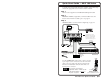
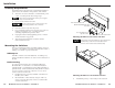
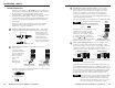
Quick Start Guide — MLS 100 Series To install and set up the MLS 100 Series switchers, follow these steps and see the appropriate section of this manual for details: Step 1 Turn all of the equipment off and disconnect the power cords. Step 2 Mount the switcher (if applicable) or affix the rubber feet to the bottom of the switcher for tabletop use. See page 2-2. Step 3 Attach the cables. See the instructions beginning on page 2-5. Laptop Projector NOTE Ground all devices.
Quick Start Guide — MLS 100 Series, cont’d To connect an MLC 206 or a third party control system, see the diagram below, and see page 2-8 for details. CONTROL/ POWER AB MLS100Series Switcher Control/Power Port NOTE You must connect a ground wire between the MLC and MLS. +12VDC input Ground ( ) External Power Supply (12VDC, 1A max.) NOTE If you use cable that has a drain wire, tie the drain wire to ground at both ends.
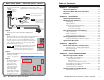
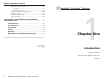
Table of Contents, cont’d Using the control program ................................................... 4-7 User Mode .............................................................................. 4-8 Switcher (MLS) Config ......................................................... 4-10 Saving and restoring configurations .................................. 4-10 Emulation mode .................................................................. 4-11 Using the help program .......................................
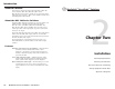
Introduction About this Manual This manual contains information about the Extron MLS 100 Series Switchers (MLS 100 A, MLS 103 V, MLS 103 SV, MLS 102 VGA) and on how to install, set up, and operate them. “MLS 100 Series switcher”, “MLS”, and “switcher” will be used interchangeably in this manual. About the MLS 100 Series Switchers The Extron MLS 100 Series Switchers are compact, quarter rack width switchers. The MLS 102 VGA, MLS 103 SV, and MLS 103 V have a 250 MHz (-3dB) video bandwidth.
Installation UL/Safety Requirements The Underwriters Laboratories (UL) requirements listed below pertain to the safe installation and operation of the switcher. 1. This unit is not to be connected to a centralized DC power source or used beyond its rated voltage range. The Extron P/S 100 and other Extron power supplies may be used with the MLS. AUT O SW MO ICH DE 1 NO RM AL 2 AU TO 3 4 A/V SW ITC HE R 2. Do not use the switcher near water.
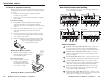
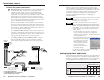
Installation, cont’d Furniture or projector mounting Rear Panel Features and Cabling Furniture mount or projector mount the MLS using the optional mounting kit (part #70-212-01, furniture; or 70-217-01, projector) as follows: Turn off and disconnect power from all the equipment before you connect cables to the MLS. 1 1. Attach the mounting brackets to the MLS with the machine screws provided. 2. If feet were previously installed on the bottom of the MLS, remove them.
Installation, cont’d Audio connections 9 The stereo audio inputs 1–3 ( 7 and 8 on page 2-5 and below) correspond to video inputs 1, 2, and 3. All four audio inputs can be selected via the front panel buttons, RS-232 control (including MLC), or the MediaLink Control Software. An audio signal from one of these inputs is output only when the corresponding input is selected. Using the MediaLink Control Software you can separately adjust the level of each of these audio inputs.
Installation, cont’d Control and power connections 11 MLC/RS-232 Power port (all models) — An Extron MediaLink Controller (MLC 206), a computer, or a third party RS-232 controller provides remote control of input switching and volume, and also provides a way to set the switcher’s audio input levels. To control and/or set up the MLS, connect a cable between this 5-pole 3.5 mm captive screw connector and an optional MLC 206, computer, or a third party RS-232 controller.
Installation, cont’d Gain and attenuation are adjustable (from -18dB to +24dB) for each input (1 through 4) via RS-232 control only (using HyperTerminal, a third party controller, or the MediaLink Control Software). The gain and attenuation for the Aux/Mix input are adjustable only via the switcher’s front panel. (See page 3-3 for Aux/Mix details.) output, it causes the audio signal to be attenuated by 6dB (gain = -6dB). For dBV the reference is 1 volt. For dBu the reference is 0.775 volts. 5.
Installation, cont’d MediaLink™ VersaTools™ Switchers Laptop LCD Projector La DV AY PL R DIS WE PO V pto p D CR 6 20 UT L/ TP OU NTRO CO WER PO 2 IN PU TS 4 A X MA .
Operation audio does not change when you switch between the four selectable audio inputs. Front Panel Features and Operation MLS 100 Series Front Panel (all models) The last selected input (including audio/video breakaway selections) will be the active input when the MLS is powered on. MLS 100 Series AUX/MIX LEVEL INPUT SELECT 1 2 3 4 MediaLink Switcher 1 2 All the MLS 100 Series switchers share the same front panel design, shown above.
Operation, cont’d the MLC. The MLC will respond with its firmware version. • Connect the MLC’s RS-232 port to a computer, start the MediaLink control software, and click on Help to display the software version, the MLC’s firmware version, and the MLS’s firmware version. Troubleshooting 1. Connect the cables between the MLS and the A/V input devices. Connect the provided power supply and a host computer, third party control system, or MediaLink Controller to the MLS’s MLC/RS-232 Power port.
Operation, cont’d MediaLink™ VersaTools™ Switchers This page has been left blank intentionally.
Serial Communication Error responses The MediaLink switcher can be remotely set up and controlled via a host computer or other device (such as a control system) attached to the rear panel MLC/RS-232 Power port. Alternatively, the switcher can be controlled by an optional MediaLink Controller (MLC) (connected to the MLS’s MLC/RS-232 Power port) or by an RS-232 device acting through the MLC.
4-4 X1 X1 X1 4! $ & ! MediaLink VersaTools Switchers • Serial Communication 1X X X Turn executive mode on. View the executive mode status. Example: Exe X7 Exe0 Exe1 Exe0 Vol X6 Vol013 Vol X6 Vol X6 Vol X6 Amt1 Amt0 Amt X7 MediaLink VersaTools Switchers • Serial Communication Zap all MLS settings/memories. Esc I Request general info. Zap (reset to default settings) Q N Query firmware version number. Request the part number. zXXX ZapXXX Video input # X1 is selected/active.
Serial Communication, cont’d Control Software for Windows® Command/response table for special function SIS commands 4-6 0 = 0.0 seconds (default), 1 = 0.5 seconds, 2 = 1.0 seconds, ... in ½ second steps up to 10 = 5.0 seconds Example: 3.5 second RGB delay. values X? and additional descriptions X? # where __ is the To view a function’s setting, use __#, where __ is the function number. In the table at left the values of the X? variable are different for each command/ function.
Serial Communication, cont’d User Mode For stand-alone MLS 100 Series switchers If an MLS 100 Series switcher is used without a MediaLink Controller, the User Mode screen, shown below, emulates the MLS’s front panel input selection buttons and also provides a means of volume control. See page 3-2 for details on basic operation.
Serial Communication, cont’d Switcher (MLS) Config The Switcher (MLS) Config screen, shown below, allows you to make adjustments without having to use the front panel controls. Emulation mode The MediaLink Control Program features an emulation mode so you can set up a MediaLink system before equipment is available on site. In emulation mode a MediaLink Controller is always included in the system. You select which MLS switcher and which control modules will be connected to the MLC.
Serial Communication, cont’d MediaLink™ VersaTools™ Switchers 5. Select the MediaLink equipment that will be part of the system you want to configure, then click on OK. The Extron MediaLink Control Program windows appear. 6. Select the desired settings in each section of the program. If you include an MLC 206 in the system, keep in mind that IR learning cannot be performed in emulation mode. You must have an MLC connected to the host computer. 7.
Specifications, Part Numbers, and Accessories Video — MLS 103 V/SV, MLS 102 VGA Gain ............................................... Bandwidth .................................... Differential phase error .............. Differential gain error ................. Crosstalk ....................................... Unity 250 MHz (-3dB) 0.01º, at 3.58 MHz and 4.43 MHz 0.01%, at 3.58 MHz and 4.43 MHz -50dB @ 5 MHz Video input — MLS 103 V/SV, MLS 102 VGA Number/signal type MLS 103 V .........................
Specifications, Part Numbers, Accessories, cont’d Impedance .................................... >10 kohms unbalanced, >20 kohms balanced, DC coupled Nominal level ............................... -20dBV (100mV), -10dBV (316mV), 0dBu (0.775V), or +4dBu (1.23V); (configurable) 0dBu = 0.775 volts (RMS). 0dBV = 1 volt +4dBu and 0dBu are professional audio line level standards. -10dBV and -20dBV are semiprofessional, computer audio, and consumer audio standards. Maximum level ............................
Specifications, Part Numbers, Accessories, cont’d Included Parts Accessories These items are included in each order for an MLS switcher: Included parts Part number to reorder MLS 100 A 60-497-01 These items can be ordered separately Accessories Part number VersaTools 1U rack shelf or Standard 60-190-20 1U rack shelf 60-190-01 or MLS 103 V 60-497-02 or MLS 103 SV 60-497-03 or MLS 102 VGA 60-497-04 MediaLink Controller MLC 206 (3-gang) (gray, black, white) 60-385-01, -02, -03 70-055-01
Specifications, Part Numbers, Accessories, cont’d MLS 100 Series Switcher Block Diagram A-8 MediaLink VersaTools Switchers • Specifications, Part #s, Accessories